EP0381786B1 - Optische Datenübertragungsvorrichtung - Google Patents
Optische Datenübertragungsvorrichtung Download PDFInfo
- Publication number
- EP0381786B1 EP0381786B1 EP89102032A EP89102032A EP0381786B1 EP 0381786 B1 EP0381786 B1 EP 0381786B1 EP 89102032 A EP89102032 A EP 89102032A EP 89102032 A EP89102032 A EP 89102032A EP 0381786 B1 EP0381786 B1 EP 0381786B1
- Authority
- EP
- European Patent Office
- Prior art keywords
- light
- transmitters
- data transmission
- axis
- transmission device
- Prior art date
- Legal status (The legal status is an assumption and is not a legal conclusion. Google has not performed a legal analysis and makes no representation as to the accuracy of the status listed.)
- Expired - Lifetime
Links
- 230000003287 optical effect Effects 0.000 title claims description 9
- 230000005540 biological transmission Effects 0.000 title description 20
- 230000005855 radiation Effects 0.000 claims description 9
- VYPSYNLAJGMNEJ-UHFFFAOYSA-N Silicium dioxide Chemical compound O=[Si]=O VYPSYNLAJGMNEJ-UHFFFAOYSA-N 0.000 description 1
- 230000001154 acute effect Effects 0.000 description 1
- 239000000969 carrier Substances 0.000 description 1
- 239000011159 matrix material Substances 0.000 description 1
- 230000005693 optoelectronics Effects 0.000 description 1
Images


Classifications
-
- A—HUMAN NECESSITIES
- A61—MEDICAL OR VETERINARY SCIENCE; HYGIENE
- A61B—DIAGNOSIS; SURGERY; IDENTIFICATION
- A61B6/00—Apparatus or devices for radiation diagnosis; Apparatus or devices for radiation diagnosis combined with radiation therapy equipment
- A61B6/56—Details of data transmission or power supply, e.g. use of slip rings
-
- H—ELECTRICITY
- H04—ELECTRIC COMMUNICATION TECHNIQUE
- H04B—TRANSMISSION
- H04B10/00—Transmission systems employing electromagnetic waves other than radio-waves, e.g. infrared, visible or ultraviolet light, or employing corpuscular radiation, e.g. quantum communication
- H04B10/80—Optical aspects relating to the use of optical transmission for specific applications, not provided for in groups H04B10/03 - H04B10/70, e.g. optical power feeding or optical transmission through water
- H04B10/801—Optical aspects relating to the use of optical transmission for specific applications, not provided for in groups H04B10/03 - H04B10/70, e.g. optical power feeding or optical transmission through water using optical interconnects, e.g. light coupled isolators, circuit board interconnections
Definitions
- the invention relates to an optical data transmission device according to the first part of patent claim 1.
- a data transmission device of this type can be used in a computer tomograph to transmit the data generated by the detector.
- the rotating part is formed by the slewing ring with the X-ray emitter and the detector.
- a transmission device of the type mentioned in a computer tomograph it is known to provide a series of light transmitters and a series of light receivers, the distances between the light transmitters and the light receivers being selected so that there is continuous data transmission between the rotating part and the fixed part (DE-A-35 30 939).
- the invention has for its object to provide an optical data transmission device according to the first part of claim 1 so that interference-free data transmission is ensured with a small number of light transmitters.
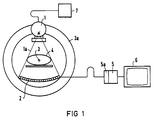
- the X-ray tube 1 shows a computer tomograph with an X-ray tube 1 as the radiation source and a radiation detector 2, which has an order of magnitude of over 100, for example 512, individual detectors arranged in a row.
- the X-ray tube 1 emits a fan-shaped beam 1a, the cross-sectional dimension of which is perpendicular to the examined layer plane and equal to the layer thickness and in the layer plane so large that radiation is penetrated through the whole object.
- the radiation detector 2 is curved around the focus of the X-ray tube 1.
- the measuring arrangement 1, 2 can be rotated about an axis 3, which coincides approximately with the longitudinal axis of the receiving object 4, with the aid of a rotating frame 3a.
- the number of detectors of the Radiation detector 2 is selected in accordance with the desired image resolution, so that, due to a rotation of the measuring arrangement 1, 2, the attenuation values of a pixel matrix of the transversal layer of the object 4 being irradiated can be calculated by a computer 5 and reproduced as an image on a display device 6.
- the x-ray tube 1 is fed by an x-ray generator 7.
- a measuring channel which leads to the computer 5, is assigned to each detector element of the radiation detector 2.
- this measuring channel amplifier circuits multiplexers and analog-digital converters are provided, which form a data acquisition system 5a.
- a particularly rapid production of a large number of sectional images of the recording object 4 is possible if the energy is transmitted from the x-ray generator 7 to the x-ray tube 1 via slip rings and the data from the detector elements of the radiation detector 2 to the data acquisition system 5a is likewise transmitted via rotating data transmission devices. Then, namely, a permanent rotation of the rotating frame 3a and thus a rapid successive scanning of a plurality of layers of the object 4 is possible.
- the rotating frame 3a rotates a frame 8, which carries four light transmitters 9 to 12 distributed symmetrically over its circumference, which emit thin, fan-shaped light beams 13 to 16, which are modulated in accordance with the information to be transmitted.
- the light beams 13 to 16 impinge on a light receiver 17, which is a photoelectric converter and feeds the received data to the data acquisition system 5a. It has a rectangular light-sensitive surface, the longitudinal extent of which is designated by L.
- the angle alpha of the longitudinal extension L with the radius is chosen so that the light receiver 17 in each position of the frame 8 and thus the light transmitter 9 to 12 at least one of these light transmitters 9 to 12 sees and that with a constant transmitted signal during rotation, despite the changing distances between the light transmitters 9 to 12 and the light receiver 17 and the relative orientation of these components to one another, a constant output signal and thus interference-free information transmission takes place.
- the light receiver 17 can be pivoted about an axis 18 lying parallel to the axis 3 and is therefore adjustable.
- the exemplary embodiment according to FIG. 3 has only two light transmitters 20, 21 on a rotating frame 19, which again emit two thin, fan-shaped light bundles 22, 23, the fan levels of which, as in the example according to FIG. 19 defined level or parallel to it.
- a light receiver 24 with a rectangular receiving surface is arranged so that this receiving surface is perpendicular to the radius.
- the light transmitters 20, 21 can be pivoted in the direction of the arrows on the frame 19 and are automatically pivoted when the frame 19 is rotated about the axis 3 in such a way that their light beams are tracked onto the light receiver 24. This makes it possible to achieve with two light transmitters that when the frame 19 is rotated fully, the light receiver 24 always sees at least one of the light transmitters 20, 21. If, for example, the frame 19 is rotated clockwise, the light transmitter 21 can also be rotated clockwise about its axis parallel to the axis 3, so that the light beam 23 remains directed at the light receiver 24.
- the central rays of the light beams 13 to 16 or 22, 23 form an acute angle with the corresponding radius, so that the light receiver 17 or 24 always has at least one light transmitter 9 to 12 , 20, 21 sees. This angle is shown for the central beam 25 of the light bundle 13 in FIG. 2.
Landscapes
- Engineering & Computer Science (AREA)
- Health & Medical Sciences (AREA)
- Life Sciences & Earth Sciences (AREA)
- Medical Informatics (AREA)
- Computer Networks & Wireless Communication (AREA)
- Physics & Mathematics (AREA)
- Biomedical Technology (AREA)
- Surgery (AREA)
- Nuclear Medicine, Radiotherapy & Molecular Imaging (AREA)
- Optics & Photonics (AREA)
- Pathology (AREA)
- Radiology & Medical Imaging (AREA)
- Biophysics (AREA)
- Heart & Thoracic Surgery (AREA)
- Molecular Biology (AREA)
- High Energy & Nuclear Physics (AREA)
- Animal Behavior & Ethology (AREA)
- General Health & Medical Sciences (AREA)
- Public Health (AREA)
- Veterinary Medicine (AREA)
- Electromagnetism (AREA)
- Signal Processing (AREA)
- Optical Communication System (AREA)
- Apparatus For Radiation Diagnosis (AREA)
- Analysing Materials By The Use Of Radiation (AREA)
Description
- Die Erfindung betrifft eine optische Datenübertragungsvorrichtung gemäß dem ersten Teil des Patentanspruches 1.
- Eine Datenübertragungsvorrichtung dieser Art kann bei einem Computertomographen zur Übertragung der vom Detektor erzeugten Daten verwendet werden. Der rotierende Teil ist dabei vom Drehkranz mit dem Röntgenstrahler und dem Detektor gebildet.
- Bei einer Übertragungsvorrichtung der eingangs genannten Art in einem Computertomographen ist es bekannt, eine Reihe von Lichtsendern und eine Reihe von Lichtempfängern vorzusehen, wobei die Abstände der Lichtsender und der Lichtempfänger so gewählt sind, daß eine kontinuierliche Datenübertragung zwischen dem rotierenden Teil und dem feststehenden Teil erfolgt (DE-A-35 30 939).
- Eine optische Datenübertragungsvorrichtung gemäß dem ersten Teil des Patentanspruches 1 ist durch das Dokument "Research Disclosure, Nr. 165, Jan. 1978, Seite 5, Nr. 16503, Havant, GB; "Optoelectronic transmission system for rotary machines" beschrieben. Bei dieser bekannten Datenübertragungsvorrichtung sind die Lichtsender und die Lichtempfänger auf ihren jeweiligen Trägern ortsfest angebracht.
- Der Erfindung liegt die Aufgabe zugrunde, eine optische Datenübertragungsvorrichtung gemäß dem ersten Teil des Patentanspruches 1 so auszubilden, daß mit einer geringen Anzahl von Lichtsendern eine störungsfreie Datenübertragung sichergestellt ist.
- Diese Aufgabe ist erfindungsgemäß gelöst durch den zweiten Teil des Patentanspruches 1. Bei der erfindungsgemäßen Datenübertragungsvorrichtung genügen bereits zwei Lichtsender in Verbindung mit einem einzigen Lichtempfänger zur störungsfreien Datenübertragung. Bei der erfindungsgemäßen Datenübertragungsvorrichtung ist sichergestellt, daß der Lichtempfänger in jeder Stellung der Datenübertragungsvorrichtung mindestens einen Lichtsender sieht und bei konstantem gesendetem Signal bei der Rotation ein konstantes Ausgangssignal liefert.
- Die Erfindung ist nachfolgend anhand der Zeichnung näher erläutert. Es zeigen:
- Fig. 1
- einen Computertomographen zur Erläuterung der Anwendung der Erfindung, und
- Fig. 2 und 3
- zwei Ausführungsformen einer bei dem Computertomographen gemäß Fig. 1 anwendbaren optischen Datenübertragungsvorrichtung.
- In der Fig. 1 ist ein Computertomograph mit einer Röntgenröhre 1 als Strahlenquelle und einem Strahlendetektor 2, der größenordnungsmäßig über 100, z.B. 512 einzelne Detektoren in einer Reihe angeordnet aufweist, dargestellt. Die Röntgenröhre 1 sendet ein fächerförmiges Strahlenbündel 1a aus, dessen Querschnittsausdehnung senkrecht zur untersuchten Schichtebene gleich der Schichtstärke und in der Schichtebene so groß ist, daß das ganze Aufnahmeobjekt von Strahlung durchsetzt wird. Der Strahlendetektor 2 ist um den Fokus der Röntgenröhre 1 gekrümmt. Die Meßanordnung 1, 2 ist um eine Achse 3, die etwa mit der Längsachse des Aufnahmeobjektes 4 zusammenfällt, mit Hilfe eines Drehrahmens 3a drehbar. Die Anzahl der Detektoren des Strahlendetektors 2 ist der gewünschten Bildauflösung entsprechend gewählt, so daß aufgrund einer Drehung der Meßanordnung 1, 2 von einem Computer 5 die Schwächungswerte einer Bildpunktmatrix der durchstrahlten Transversalschicht des Aufnahmeobjektes 4 berechnet und als Bild auf einem Sichtgerät 6 wiedergegeben werden können. Die Röntgenröhre 1 wird von einem Röntgengenerator 7 gespeist.
- Jedem Detektorelement des Strahlendetektors 2 ist ein Meßkanal zugeordnet, der zum Computer 5 führt. In diesem Meßkanal sind Verstärkerschaltungen, Multiplexer und Analog-Digital-Wandler vorgesehen, die ein Datenerfassungssystem 5a bilden.
- Eine besonders schnelle Anfertigung einer Vielzahl von Schnittbildern des Aufnahmeobjektes 4 ist möglich, wenn die Energie vom Röntgengenerator 7 zur Röntgenröhre 1 über Schleifringe und die Daten der Detektorelemente des Strahlendetektors 2 zum Datenerfassungssystem 5a ebenfalls über rotierende Datenübertragungsvorrichtungen übertragen werden. Dann ist nämlich eine Dauerrotation des Drehrahmens 3a und damit eine schnelle aufeinander folgende Abtastung einer Vielzahl von Schichten des Aufnahmeobjektes 4 möglich.
- In der Fig. 2 ist eine optische Datenübertragungsvorrichtung zur kontaktlosen, optischen Übertragung der Daten der Detektorelemente des Strahlendetektors 2 dargestellt. Mit dem Drehrahmen 3a rotiert ein Rahmen 8, welcher symmetrisch auf seinem Umfang verteilt vier Lichtsender 9 bis 12 trägt, die dünne, fächerförmige Lichtbündel 13 bis 16 aussenden, welche der jeweils zu übertragenden Information entsprechend moduliert werden. Die Lichtbündel 13 bis 16 treffen auf einem Lichtempfänger 17 auf, der ein lichtelektrischer Wandler ist und die empfangenen Daten dem Datenerfassungssystem 5a zuführt. Er besitzt eine rechteckförmige lichtempfindliche Fläche, deren Längsausdehnung mit L bezeichnet ist. Der Winkel Alpha der Längsausdehnung L mit dem Radius wird so gewählt, daß der Lichtempfänger 17 in jeder Stellung des Rahmens 8 und damit der Lichtsender 9 bis 12 mindestens einen dieser Lichtsender 9 bis 12 sieht und daß bei konstantem gesendetem Signal bei der Rotation trotz der sich ändernden Abstände zwischen den Lichtsendern 9 bis 12 und dem Lichtempfänger 17 und der relativen Ausrichtung dieser Komponenten zueinander ein konstantes Ausgangssignal und damit eine störungsfreie Informationsübertragung erfolgt. Hierzu ist der Lichtempfänger 17 um eine parallel zur Achse 3 liegende Achse 18 schwenkbar und damit einstellbar.
- Die Fig. 2 zeigt, daß bereits mit vier Lichtsendern 9 bis 12 und einem einzigen Lichtempfänger 17 eine störungsfreie Datenübertragung sichergestellt ist.
- Das Ausführungsbeispiel gemäß Fig. 3 weist auf einem rotierenden Rahmen 19 nur zwei Lichtsender 20, 21 auf, die wieder zwei dünne, fächerförmige Lichtbündel 22, 23 aussenden, deren Fächerebenen wie bei dem Beispiel gemäß Fig. 2 in der durch den Rahmen 8 bzw. 19 definierten Ebene oder parallel dazu liegen. Ein Lichtempfänger 24 mit einer rechteckförmigen Empfangsfläche ist so angeordnet, daß diese Empfangsfläche senkrecht zum Radius liegt. Die Lichtsender 20, 21 sind in Richtung der gezeichneten Pfeile auf dem Rahmen 19 schwenkbar und werden bei der Drehung des Rahmens 19 um die Achse 3 automatisch so verschwenkt, daß ihre Lichtbündel auf den Lichtempfänger 24 nachgeführt werden. Dadurch ist es möglich, mit bereits zwei Lichtsendern zu erreichen, daß bei einer vollen Drehung des Rahmens 19 der Lichtempfänger 24 immer mindestens einen der Lichtsender 20, 21 sieht. Wird beispielsweise der Rahmen 19 im Uhrzeigersinn gedreht, so kann dabei der Lichtsender 21 um seine zur Achse 3 parallele Achse ebenfalls im Uhrzeigersinn verdreht werden, so daß das Lichtbündel 23 auf den Lichtempfänger 24 gerichtet bleibt.
- Sowohl bei dem Ausführungsbeispiel gemäß Fig. 2 als auch gemäß Fig. 3 bilden die Zentralstrahlen der Lichtbündel 13 bis 16 bzw. 22, 23 mit dem entsprechenden Radius einen spitzen Winkel, so daß der Lichtempfänger 17 bzw. 24 immer mindestens einen Lichtsender 9 bis 12, 20, 21 sieht. Dieser Winkel ist für den Zentralstrahl 25 des Lichtbündels 13 in Fig. 2 eingezeichnet.
Claims (2)
- Optische Datenübertragungsvorrichtung zur Datenübertragung zwischen einem rotierenden Teil (8, 19) und einem feststehenden Teil, bei der auf einem Teil (8, 19) eine Anzahl von Lichtsendern (9 bis 12, 20, 21) auf einem Kreis angeordnet ist, deren den zu übertragenden Daten entsprechend modulierte Strahlung von einem Lichtempfänger (17, 24) auf dem anderen Teil empfangen wird, wobei die Zentralstrahlen (25) mit dem Radius des die Lichtsender (9 bis 12, 20, 21) tragenden Teils (8, 19), welcher zum jeweiligen Lichtsender (9 bis 12, 20, 21) verläuft, jeweils einen Winkel bilden, dadurch gekennzeichnet, daß die Lichtsender (9 bis 12, 20, 21) fächerförmige Lichtbündel (13 bis 16, 22, 23) aussenden, deren Fächerebene in der durch den Kreis definierten Ebene oder parallel dazu liegt, daß der Lichtempfänger (17, 24) innerhalb des rotierenden Teiles (9 bis 12, 20, 21) angeordnet ist, daß die Lichtbündel (13 bis 16, 22, 23) nach innen gerichtet sind, und daß die Lichtsender (20, 21) auf dem rotierenden Teil (8, 19) während der Rotation um eine zur Drehachse (3) parallele Achse derart drehbar sind, daß ihre Lichtbündel (22, 23) auf den Lichtempfänger (24) nachgeführt werden.
- Optische Datenübertragungsvorrichtung nach Anspruch 1, dadurch gekennzeichnet, daß der Lichtempfänger (17) um eine zur Drehachse (3) parallele Achse (18) einstellbar ist.
Priority Applications (4)
| Application Number | Priority Date | Filing Date | Title |
|---|---|---|---|
| EP89102032A EP0381786B1 (de) | 1989-02-06 | 1989-02-06 | Optische Datenübertragungsvorrichtung |
| DE58907515T DE58907515D1 (de) | 1989-02-06 | 1989-02-06 | Optische Datenübertragungsvorrichtung. |
| US07/451,800 US4996435A (en) | 1989-02-06 | 1989-12-18 | Optical system for transmitting data between a stationary part and a rotating part |
| JP2025900A JPH02239734A (ja) | 1989-02-06 | 1990-02-05 | 光学式データ伝送装置 |
Applications Claiming Priority (1)
| Application Number | Priority Date | Filing Date | Title |
|---|---|---|---|
| EP89102032A EP0381786B1 (de) | 1989-02-06 | 1989-02-06 | Optische Datenübertragungsvorrichtung |
Publications (2)
| Publication Number | Publication Date |
|---|---|
| EP0381786A1 EP0381786A1 (de) | 1990-08-16 |
| EP0381786B1 true EP0381786B1 (de) | 1994-04-20 |
Family
ID=8200943
Family Applications (1)
| Application Number | Title | Priority Date | Filing Date |
|---|---|---|---|
| EP89102032A Expired - Lifetime EP0381786B1 (de) | 1989-02-06 | 1989-02-06 | Optische Datenübertragungsvorrichtung |
Country Status (4)
| Country | Link |
|---|---|
| US (1) | US4996435A (de) |
| EP (1) | EP0381786B1 (de) |
| JP (1) | JPH02239734A (de) |
| DE (1) | DE58907515D1 (de) |
Cited By (1)
| Publication number | Priority date | Publication date | Assignee | Title |
|---|---|---|---|---|
| DE102009049052A1 (de) | 2009-10-12 | 2011-04-21 | Siemens Aktiengesellschaft | Computertomographiegerät mit einer Vorrichtung zur Datenübertragung und Verfahren zur Datenübertragung in einem Computertomographiegerät |
Families Citing this family (13)
| Publication number | Priority date | Publication date | Assignee | Title |
|---|---|---|---|---|
| US5229871A (en) * | 1991-08-29 | 1993-07-20 | Kabushiki Kaisha Toshiba Corporation | Optical data link for communicating data between a stationary member and a rotating member and an X-ray computer tomography apparatus incorporating the same |
| JP3643384B2 (ja) * | 1992-01-14 | 2005-04-27 | 株式会社東芝 | X線断層撮影装置 |
| JP3478566B2 (ja) * | 1993-09-16 | 2003-12-15 | 株式会社東芝 | X線ctスキャナ |
| DE4342778A1 (de) * | 1993-12-15 | 1995-06-22 | Siemens Ag | Kontaktlose Datenübertragungsvorrichtung |
| CN1073767C (zh) * | 1994-06-21 | 2001-10-24 | 滑环和设备制造有限公司 | 发送和接收旋转光信号的设备 |
| JP4495794B2 (ja) * | 1999-04-28 | 2010-07-07 | 株式会社東芝 | 信号伝送装置及びx線ctスキャナ |
| US7027737B2 (en) * | 2002-09-26 | 2006-04-11 | Siemens Aktiengesellschaft | Method and apparatus for transmitting data from a rotary part to a stationary part of a data generating system |
| DE10330647B4 (de) * | 2003-07-07 | 2005-12-22 | Siemens Ag | Vorrichtung zur Übertragung optischer Signale zwischen einem rotierenden und einem stationären Teil einer Maschine |
| US7477721B2 (en) * | 2004-04-27 | 2009-01-13 | Koninklijke Philips Electronics N.V. | Open access air bearing gantry |
| WO2005117706A1 (de) * | 2004-06-03 | 2005-12-15 | Siemens Aktiengesellschaft | Vorrichtung zur kontaktlosen übermittlung von signalen und messdaten bei einem computertomografen |
| WO2010026914A1 (ja) * | 2008-09-02 | 2010-03-11 | 株式会社 日立メディコ | X線ct装置 |
| WO2010137430A1 (ja) * | 2009-05-25 | 2010-12-02 | Dic株式会社 | 多孔体の製造方法ならびにそれによって得られた多孔体、積層体及び皮革様シート |
| US10326561B2 (en) * | 2015-06-24 | 2019-06-18 | Toshiba Medical Systems Corporation | Mirror-ring assembly for bi-directional optical communication between a rotor and a stator |
Family Cites Families (4)
| Publication number | Priority date | Publication date | Assignee | Title |
|---|---|---|---|---|
| GB1575672A (en) * | 1977-05-05 | 1980-09-24 | Standard Telephones Cables Ltd | Information transfer |
| DE3205065A1 (de) * | 1982-02-12 | 1983-08-18 | Philips Patentverwaltung Gmbh, 2000 Hamburg | Vorrichtung zum uebertragen von signalen zwischen zwei relativ zueinander drehbaren teilen |
| DE3530939A1 (de) * | 1985-08-29 | 1987-03-12 | Siemens Ag | Optische datenuebertragungsvorrichtung |
| US4854662A (en) * | 1988-09-27 | 1989-08-08 | Eastman Kodak Company | Optical data signal apparatus for optically coupling a plurality of data channels between stationary and rotating systems |
-
1989
- 1989-02-06 EP EP89102032A patent/EP0381786B1/de not_active Expired - Lifetime
- 1989-02-06 DE DE58907515T patent/DE58907515D1/de not_active Expired - Fee Related
- 1989-12-18 US US07/451,800 patent/US4996435A/en not_active Expired - Fee Related
-
1990
- 1990-02-05 JP JP2025900A patent/JPH02239734A/ja active Pending
Cited By (1)
| Publication number | Priority date | Publication date | Assignee | Title |
|---|---|---|---|---|
| DE102009049052A1 (de) | 2009-10-12 | 2011-04-21 | Siemens Aktiengesellschaft | Computertomographiegerät mit einer Vorrichtung zur Datenübertragung und Verfahren zur Datenübertragung in einem Computertomographiegerät |
Also Published As
| Publication number | Publication date |
|---|---|
| DE58907515D1 (de) | 1994-05-26 |
| US4996435A (en) | 1991-02-26 |
| EP0381786A1 (de) | 1990-08-16 |
| JPH02239734A (ja) | 1990-09-21 |
Similar Documents
| Publication | Publication Date | Title |
|---|---|---|
| EP0381786B1 (de) | Optische Datenübertragungsvorrichtung | |
| DE2451301C2 (de) | Radiographieapparat mit einer Gruppe von Hauptdetektoren zum Empfangen von zu einem ebenen Bündel kollimierter Röntgenstrahlung und mit zusätzlichen, außerhalb des Bündels angeordneten Detektoreinrichtungen | |
| DE60026090T2 (de) | Strahlungsdetektor | |
| EP0466956A1 (de) | Computertomograph | |
| DE2614083B2 (de) | Röntgenschichtgerät zur Herstellung von Transversalschichtbildern | |
| DE2709600A1 (de) | Radiographisches geraet | |
| DE4218692B4 (de) | Einrichtung zum Übertragen von Daten zwischen einem rotierenden und einem stationären Teil | |
| EP0279294A1 (de) | Zahnärztliche Röntgendiagnostikeinrichtung zur Erstellung von Panorama-Schichtaufnahmen vom Kiefer eines Patienten | |
| DE2166526A1 (de) | Einrichtung zur abbildung eines objektes mittels elektromagnetischer strahlung oder korpuskelstrahlung hoher energei | |
| EP0871044B1 (de) | Verfahren zur Verbesserung der Bildschärfe in der Röntgen-Computertomographie | |
| DE69728894T2 (de) | Vorrichtung und verfahren zur signalverarbeitung der photodetektoranordnung einer gammakamera | |
| DE2614377C3 (de) | ||
| DE2648503C2 (de) | Computer-Tomograph | |
| DE2462509B2 (de) | Radiographisches Gerät zum Untersuchen der Absorption von Röntgen- oder T -Strahlung in einer Querschnittsscheibe eines Körpers | |
| DE2828963C2 (de) | Computer-Tomopraph | |
| EP0381785B1 (de) | Rotierende Datenübertragungsvorrichtung | |
| DE2721712C2 (de) | Computer-Tomograph | |
| DE2702009A1 (de) | Radiographisches geraet | |
| DE2640832C3 (de) | Elektroakustische Vorrichtung zum Lesen eines eindimensionalen optischen Bildes | |
| DE2521889B2 (de) | Geraet zur untersuchung eines koerpers mittels durchdringender strahlung | |
| DE2413041C2 (de) | Schaltungsanordnung zur Korrektur von Bildfehlern bei einer Szintillationskamera | |
| EP0367856B1 (de) | Computer-Tomograph | |
| DE4217359C2 (de) | Einrichtung zur Inspektion eines Gegenstandes | |
| DE3120567A1 (de) | Streustrahlen-untersuchungsanordnung | |
| DE2011104B2 (de) | Geraet zum aufnehmen und aufzeichnen der raeumlichen verteilung radioaktiver strahlungsquellen in einem untersuchungsobjekt mit einer szintillationskamera und mit mitteln zur selektiven scharfeinstellung auf eine waehlbare schnittebene |
Legal Events
| Date | Code | Title | Description |
|---|---|---|---|
| PUAI | Public reference made under article 153(3) epc to a published international application that has entered the european phase |
Free format text: ORIGINAL CODE: 0009012 |
|
| AK | Designated contracting states |
Kind code of ref document: A1 Designated state(s): DE FR GB |
|
| 17P | Request for examination filed |
Effective date: 19900919 |
|
| 17Q | First examination report despatched |
Effective date: 19921027 |
|
| GRAA | (expected) grant |
Free format text: ORIGINAL CODE: 0009210 |
|
| AK | Designated contracting states |
Kind code of ref document: B1 Designated state(s): DE FR GB |
|
| PG25 | Lapsed in a contracting state [announced via postgrant information from national office to epo] |
Ref country code: GB Effective date: 19940420 Ref country code: FR Effective date: 19940420 |
|
| REF | Corresponds to: |
Ref document number: 58907515 Country of ref document: DE Date of ref document: 19940526 |
|
| EN | Fr: translation not filed | ||
| GBV | Gb: ep patent (uk) treated as always having been void in accordance with gb section 77(7)/1977 [no translation filed] |
Effective date: 19940420 |
|
| PLBE | No opposition filed within time limit |
Free format text: ORIGINAL CODE: 0009261 |
|
| STAA | Information on the status of an ep patent application or granted ep patent |
Free format text: STATUS: NO OPPOSITION FILED WITHIN TIME LIMIT |
|
| 26N | No opposition filed | ||
| PGFP | Annual fee paid to national office [announced via postgrant information from national office to epo] |
Ref country code: DE Payment date: 19970418 Year of fee payment: 9 |
|
| PG25 | Lapsed in a contracting state [announced via postgrant information from national office to epo] |
Ref country code: DE Free format text: LAPSE BECAUSE OF NON-PAYMENT OF DUE FEES Effective date: 19981103 |