EP0382424A2 - Tête de lecture pour un dispositif de lecture d'images - Google Patents
Tête de lecture pour un dispositif de lecture d'images Download PDFInfo
- Publication number
- EP0382424A2 EP0382424A2 EP90301109A EP90301109A EP0382424A2 EP 0382424 A2 EP0382424 A2 EP 0382424A2 EP 90301109 A EP90301109 A EP 90301109A EP 90301109 A EP90301109 A EP 90301109A EP 0382424 A2 EP0382424 A2 EP 0382424A2
- Authority
- EP
- European Patent Office
- Prior art keywords
- image pickup
- light
- subject
- polarizing
- polarization plane
- Prior art date
- Legal status (The legal status is an assumption and is not a legal conclusion. Google has not performed a legal analysis and makes no representation as to the accuracy of the status listed.)
- Granted
Links
Images


Classifications
-
- G—PHYSICS
- G02—OPTICS
- G02B—OPTICAL ELEMENTS, SYSTEMS OR APPARATUS
- G02B27/00—Optical systems or apparatus not provided for by any of the groups G02B1/00 - G02B26/00, G02B30/00
- G02B27/28—Optical systems or apparatus not provided for by any of the groups G02B1/00 - G02B26/00, G02B30/00 for polarising
- G02B27/281—Optical systems or apparatus not provided for by any of the groups G02B1/00 - G02B26/00, G02B30/00 for polarising used for attenuating light intensity, e.g. comprising rotatable polarising elements
-
- G—PHYSICS
- G02—OPTICS
- G02B—OPTICAL ELEMENTS, SYSTEMS OR APPARATUS
- G02B21/00—Microscopes
- G02B21/06—Means for illuminating specimens
- G02B21/08—Condensers
- G02B21/12—Condensers affording bright-field illumination
-
- G—PHYSICS
- G02—OPTICS
- G02B—OPTICAL ELEMENTS, SYSTEMS OR APPARATUS
- G02B23/00—Telescopes, e.g. binoculars; Periscopes; Instruments for viewing the inside of hollow bodies; Viewfinders; Optical aiming or sighting devices
- G02B23/02—Telescopes, e.g. binoculars; Periscopes; Instruments for viewing the inside of hollow bodies; Viewfinders; Optical aiming or sighting devices involving prisms or mirrors
- G02B23/06—Telescopes, e.g. binoculars; Periscopes; Instruments for viewing the inside of hollow bodies; Viewfinders; Optical aiming or sighting devices involving prisms or mirrors having a focussing action, e.g. parabolic mirror
-
- G—PHYSICS
- G02—OPTICS
- G02B—OPTICAL ELEMENTS, SYSTEMS OR APPARATUS
- G02B27/00—Optical systems or apparatus not provided for by any of the groups G02B1/00 - G02B26/00, G02B30/00
- G02B27/0018—Optical systems or apparatus not provided for by any of the groups G02B1/00 - G02B26/00, G02B30/00 with means for preventing ghost images
-
- G—PHYSICS
- G02—OPTICS
- G02B—OPTICAL ELEMENTS, SYSTEMS OR APPARATUS
- G02B5/00—Optical elements other than lenses
- G02B5/30—Polarising elements
Definitions
- This invention relates to an image pickup head for an image pickup device adapted to pick up an image of the surface of a subject in various fields such as medical fields, industrial fields and the like.
- Image pickup devices which are adapted to abut have connected to them an image pickup head including built-in light projecting means for illuminating the surface of a section to be observed (hereinafter referred to as an "observed section") of a subject in order to display a magnified image of the surface of the observed section at a monitor image plane, have been used in various fields.
- an image pickup head including built-in light projecting means for illuminating the surface of a section to be observed (hereinafter referred to as an "observed section") of a subject in order to display a magnified image of the surface of the observed section at a monitor image plane, have been used in various fields.
- an image pickup head including built-in light projecting means for illuminating the surface of a section to be observed (hereinafter referred to as an "observed section") of a subject in order to display a magnified image of the surface of the observed section at a monitor image plane, have been used in various fields.
- illumination mainly comprising light which is vertically projected onto the surface of the observed section of a subject against which the image pickup head is abutted tends to cause the reflection of the light on the abutment surface of the subject to be increased.
- abutment surface tends to cause the reflection of the light on the abutment surface of the subject to be increased.
- Illumination mainly using horizontally projected light i.e. light which is projected parallel to the abutment surface of the observed section of a subject generally fails to illuminate satisfactorily fine recesses which might exist on the abutment surface.
- a finely recessed portion of the abutment surface would appear relatively dark on a monitor image plane for displaying a magnified image of the abutment surface, resulting in an inability to observe fine in the abutment surface of the subject.
- the present applicants proposed a light guiding device for illumination suitable for displaying a magnified image of the observed surface of a subject including fine recesses, as disclosed in European Patent Application No. 89.305570.7.
- the proposed light guiding device is adapted to be used with an image pickup head and is constructed so as to eliminate the adverse effect of light reflected on the surface of the observed section of a subject, to permit a three-dimensional magnified image of the surface to be satisfactorily displayed on a monitor image plane.
- elimination of light reflected on the observed surface renders the observation of light reflection on the surface substantially impossible.
- the so-called “shining condition" of the skin such as the complexion and glow of the surface of the skin vary depending upon the health condition of the skin, the degree of aging of the skin and so on. Therefore, the "shining conditions" of the skin are useful in determining the condition of the skin.
- the detection of the shining condition of the skin for this purpose can be carried out on the basis of the degree of reflection of light at the skin surface.
- it is generally effective and desirable to eliminate the reflection of light at the surface of the observed section of a subject in order to observe the subject accurately it is also desirable to make the detection of light reflection at the surface of the observed section possible.
- the image obtained of the observed section of a subject when accompanied by light reflected at the observed section satisfactorily shows the three-dimensional or stereo configuration of the observed section, whereas the image of the observed section which is free of reflected light effectively indicates the colour of the observed section.
- the observed section is the skin of a human body
- a part of light projected onto the skin penetrates the outer layer of the skin, thereby causing the structure of the outer layer to be clearly observed.
- the present applicants have concluded that the substantially simultaneous observation of both an image of the subject accompanied by light reflected at the surface of the observed section and an image thereof free of reflected light significantly contributes to the detecting of or finding cells in which a cancer may have developed, and the like.
- the present invention has been made in view of the foregoing.
- an object of the present invention to provide an image pickup head for an image pickup device which is capable of permitting the observed section of a subject to be illuminated with as uniform an illuminance as possible.
- an image pickup head for an image pickup device comprising: a head body; an optical system within the head body; an image pickup element in the head body arranged to pick up an optical image introduced through the optical system; and a light guide located annularly about the optical axis of the optical system in the head body arranged to project light for illumination supplied from a light source through the projection end of the light guide on to the surface of a subject; characterised by: a first polarizing element having a predetermined polarization plane, arranged in the optical path of light projected from the projection end of the light guide onto the subject; a second polarizing element having a predetermined polarization plane, arranged on the optical path of light reflected at the subject and guided to the image pickup element; and operative means for varying the polarization planes of first and second polarizing elements relative to each other.
- the operation means comprises rotation means for rotating any one of the first and second polarizing elements about the optical axis of the optical system to vary their polarization planes relative to each other.
- the operation means may comprise a slide system for causing at least one second polarizing plate, having a predetermined polarization plane crossing the polarization plane of a first polarizing plate, to enter retractably the optical path of the reflected light.
- the second polarizing element has a predetermined polarization plane crossing the polarization plane of the first polarizing element and is arranged in the optical path of light reflected at the subject and guided to the image pickup element, and a rotation element is provided on the side of the first or second polarizing element facing the subject arranged to rotate the polarization plane of one of the first and second polarizing elements relative to the polarization plane of the other polarizing element.
- the rotation element comprises a liquid crystal element.
- the rotation element may comprise a PLZT.
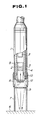
- FIG. 1 shows a first embodiment of an image pickup head for an image pickup device according to the present invention.
- the pickup head includes a head body comprising a lens barrel or tube 1, in which a magnifying optical system 2 is located.
- the lens tube 1 also houses an image pickup element of CCD image sensor 3 for converting an optical image formed through the magnifying optical system 2 into an electrical signal.
- the image pickup element 3 is positioned at the proximal end of the lens tube 1 and is connected to a display unit (not shown) including a monitor image plane for displaying a magnified image obtained through the image pickup element 3.
- the image pickup head also includes a plurality of optical fibres 5 on the inner surface of the lens tube 1 located about the optical axis of the magnifying optical system 2 so as to form a part of the lens tube 1.
- the optical fibres 5 are annularly arranged in a manner to surround the magnifying optical system 2 and be close to one another, thus forming a light guide 4.
- the light guide 4 is so arranged that its distal end terminates at the distal end of the lens tube 1.
- the optical fibres 5 are bundled in front of a light source (not shown) and then guided to the proximal end of the lens tube 1. Then, the optical fibres 5 extend towards the distal end of the lens tube 1 while being evenly arranged in such a way that they are annularly close to one another.
- Such an arrangement of the light guide 4 permits light projected from the light guide 4 onto the surface of the observed section of a subject 6 to illuminate the surface uniformly.
- the image pickup head also includes an objective contact member 7 of a cylindrical configuration which is threadedly connected to the distal end of the lens tube 1 through a cylindrical member or ring 8 which is itself threadedly connected to the lens tube 1. The axial position can then be varied for the adjustment of focus of the head.
- the objective contact member 7 extends in the direction of the optical axis of the magnifying optical system 2 and engages the ring 8 about the optical axis of the magnifying optical system 2.
- the objective contact member 7 has an opening at its distal end, which is brought into contact with the surface of the observed section of the subject 6 to stabilise the positional relationship between the lens tube 1 and the surface of the observed section of the subject 6 with this arrangement, the objective contact cylinder 7 can be rotated relative to the lens tube 1, resulting in the focus of the lens tube 1 or magnifying optical system 2 and therefore the image pickup head being adjusted.
- the objective contact member 7 has a cylindrical shape. However, it may be formed into any other suitable shape depending upon the properties of the surface of the observed section of the subject 6. For example, it may be expanded or constricted at its distal end.
- the image pickup head further includes a first polarizing element or plate 9 having an annular shape located in the objective contact member 7.
- the first polarizing plate 9 is positioned in the optical path of light discharged from the distal end or projection end of the light guide 4 towards the surface of the observed section of the subject 6, so that light from this distal end of the light guide 4 passes through the first polarizing plate 9 for illuminating the surface of the subject 6.
- the image pickup head also includes a second polarizing element or plate 12 of a circular shape positioned in the optical path of light reflected at the observed section of the subject 6 and directed towards the image pickup element 3.
- the second polarizing plate 12 is located inside an opening 11 in a mounting cylinder 10 in which the magnifying optical system 2 is housed.
- the objective contact member 7 is placed in contact with the surface of the observed section of the subject 6 and then rotated to cause movement in the axial direction, resulting in adjustment of the focus of the image pickup head.
- Light for illumination is radiated from the light source (not shown) and is annularly uniformly discharged from the optical fibres 5 constituting the light guide 4 and permeates through the first polarizing plate 9, positioned in the optical path of the light, so that the light is linearly polarized.
- the image pickup head of the illustrated embodiment may accomplish satisfactory illumination on the abutment surface of the subject 6 even when any unevenness exists on the abutment surface.
- Light reflected at the abutment surface of the observed section of the subject 6 is linearly or straightly polarized light having been polarized by the first polarizing plate 9, and has a polarization plane in a specific vector direction. Also, the portion of the polarized light reaching the interior of the subject through the abutment surface is reflcted within the interior after being changed, at the abutment surface, into circularly polarized light having a polarization plane in every direction corresponding to the configuration of the abutment surface.
- the linearly polarized light reflected on the abutment surface and the circularly polarized light reflected within the interior of the subject 6 are guided together to the second polarizing plate 12, which either allows only the linearly polarized light to permeate through or removes it, so that either only the linearly polarized light or only the circularly polarized light may be selectively guided through the magnifying optical system 2 to the image pickup element 3. This results in a magnified image of the abutment surface being supplied to the image pickup element 3.
- turning the objective contact member 7 causes the first polarizing plate 9 and second polarizing plate 12 to be rotated relative to each other, leading to a deviation between the polarization planes of the two polarizing plates.
- Adjustment of the relative angle between the polarizing plates 9 and 12 may readily selectively provide an output for the image pickup element 3 which is either accompanied by, or free of, light reflected at the abutment surface of the subject 6.
- the image pickup head of the first embodiment permits a magnified image of the abutment surface of the subject 6 to be distinctly formed at the light receiving plane of the image pickup element 3, and is then displayed on the image plane of a monitor display device such as a TV monitor.
- the image pickup head is suitable not only for a magnifying observation of the tissues of the skin or an organ of a human body but also the observation of various kinds of subjects, by constructing the objective contact member appropriately to each of the subjects.
- relative rotation between the first polarizing plate 9 and the second polarizing plate 12 is carried out manually.
- the present invention may be constructed so as to carry out this relative rotation automatically.
- Figures 2 to 4 show a second embodiment of an image pickup head according to the present invention, which is adapted to carry out relative rotation between the two polarizing plates automatically and rapidly.
- the image pickup head of the second embodiment includes a head body comprising a lens barrel or tube 1, in which a magnifying optical system 2 is housed, as in the first embodiment.
- the lens tube 1 has an image pickup element 3 for converting an optical image formed through the magnifying optical system 2 into an electrical signal.
- the image pickup element 3 is located at the proximal end of the lens tube 1 and connected to a monitor display unit such as a TV monitor (not shown) including an image plane for displaying the magnified image obtained through the image pickup element 3.
- the image pickup head also includes a plurality of optical fibres 5 on the inner surface of the lens tube 1 arranged about the optical axis of the magnifying optical system 2.
- the optical fibres 5 are annularly arranged in a manner to be close to one another and surround the magnifying optical system 2, thus forming a light guide 4.
- the light guide 4 is so arranged that its distal end terminates at the distal end of the lens tube 1.
- the optical fibres 5 are bundled in front of a light source (not shown) and then guided to the proximal end of lens tube 1. Then, the optical fibres 5 extend towards the distal end of the lens tube 1 while being evenly arranged in such a way that they are annularly close to one another.
- Such an arrangement of the light guide 4 permits light discharged from the light guide 4 to illuminate uniformly the surface of the observed section of a subject 6.
- the lens tube 1 is so formed that its distal end protrudes by an amount required for the adjustment of the focus of the image pickup head, resulting in the provision of an objective contact member 7 of cylindrical shape which extends in the direction of the optical axis of the magnifying optical system 2.
- the objective contact member 7 has at its distal end an opening, which is brought into contact with the surface of the observed section of the subject 6 to stabilise the positional relationship between the lens tube 1 and the subject 6. Also, the objective contact member serves to block any foreign or external light from entering the image pickup head.
- the objective contact member 7 is connected directly to the lens tube 1. However, it may be connected to the distal end of the lens tube 1 through a cylindrical member or ring 8 adapted to be threadedly adjusted for the adjustment of focus of the lens tube as in the first embodiment.
- the objective contact member 7 has a cylindrical shape as in the first embodiment. However, it may be formed into any other suitable shape depending upon the properties of the abutment surface of the observed section of the subject 6.
- it may be expanded or constricted at its distal end.
- a first polarizing plate 9 is provided, contiguous with an opening 11 in a mounting cylinder 10 for the magnifying optical system 2.
- the first polarizing plate 9 is annular and arranged coaxially with the optical axis of the magnifying optical system. It is positioned in the optical path of light for illumination discharged from the distal end or projection end of the light guide towards the subject, so that the light discharged from the light guide 4 may be projected on the abutment surface of the observed section of the subject.
- a second polarizing plate 12 which is circular and has a polarization plane crossing that of the first polarizing plate 9, is arranged so as to be combined with the first polarizing plate 9 and received in the central opening of the first polarizing plate 9.
- the second polarizing plate 12 is positioned in the optical path of light reflected from the subject 6.
- An A.C. oscillator 17 is connected to the liquid crystal element 13 for applying a D.C. voltage to control the rotation of the polarization plane across a liquid crystal material (described below) through transparent electrodes 14, external electrodes 15 ( Figure 4) and through a lead wire 16 ( Figure 2). The oscillator 17 will be described below.
- Figure 3(a) is an exploded perspective view showing the polarization panel 19 prior to assembly
- Figure 3(b) is a vertical sectional view of the panel 19 after assembly
- Figure 3(c) is a front elevation of the panel 19 after assembly, viewed from the polarization plate side.
- the liquid crystal element 13, as shown in Figure 4, includes two transparent plates 20 made of a glass material or the like and a nematic liquid crystal material 21 interposed between the transparent plates 20.
- the transparent electrodes 14 are arranged on each surface of the liquid crystal 21 and are made of tin oxide, indium oxide or the like.
- the transparent electrodes 14 are connected to the corresponding external electrodes 15, respectively, which are then connected through the lead wire 16 to the A.C. oscillator 17 ( Figure 2).
- the oscillator 17 is connected to a control switch 22, which allows A.C. power to be supplied from the A.C. oscillator 17 to the transparent electrodes 14 to apply an A.C.
- the liquid crystal element 13 readily controls rotation of the polarization plane of the second polarizing plate 12 in a vector direction.
- control of the applied voltage facilitates adjustment of rotation angle of the polarization plane. It is also possible to pass an A.C. current between the transparent electrodes 14 in a manner to cause the phases to be opposite to each other, thereby rendering the average value of the voltage applied across the liquid crystal 21 zero. This tends to prolong the life of the liquid crystal 21.
- the A.C. oscillator 17 and control switch 22 directly on the image pickup head. They may be connected through the lead wire 16 to the image pickup head. In this instance, they may be operated by remote control.
- the oscillation frequency of the A.C. oscillator 17 is conveniently set within the range between 300Hz and 50KHz. When the oscillation frequency is set at a level as low as 60Hz which is the output frequency of the monitor TV, the image displayed on the TV monitor is accompanied by a beat.
- the setting of the frequency at a level above 50KHz does not exhibit any meritorious effect and rather causes an increase in power consumption.
- the frequency is preferably set at about 1KHz. This is preferable also from the viewpoint of the manufacturing of the oscillator 17, because an oscillator of such a frequency is relatively easily manufactured.
- the image pickup head may be constructed into any desired size depending upon its intended use, because the liquid crystal element 13 can readily be small-sized.
- the liquid crystal 21 there may be substituted a material capable of rotating the polarization plane of the polarizing plate by an electrical treatment such as, for example, PLZT.
- the PLZT comprising a composite material of oxides of lead (Pb), lanthanum (La), zirconium (Zr) and titanium (Ti) and is a transparent crystal made by sintering the oxides in powder form under pressure.
- the polarization characteristics of PLZT vary when it is subject to electrical treatment.
- a material which is capable of rotating the polarization plane of the polarizing plate when magnetism is applied to it may be used for this purpose in place of the liquid crystal 21.
- the remainder of the second embodiment may be constructed in substantially the same manner as the first embodiment.
- the image pickup head of the second embodiment may be operated in substantially the same way as the first embodiment, in order to check the observed section of a subject 6.
- the objective contact member 7 is placed against the surface of the observed section.
- a part of the polarized light reaches the interior of the subject 6 through the abutment surface and is reflected within the interior. It is therefore changed, at the abutment surface, into circularly polarized light, having a polarization plane in every direction corresponding to the configuration of the abutment surface.
- the linearly polarized light reflected at the abutment surface and the circularly polarized light reflected within the interior of the subject 6 are guided to the liquid crystal element 13.
- the liquid crystal element 13 causes the direction of the polarization plane of the reflected light to be rotated by a predetermined angle, so that only reflected light having a polarization plane in the same vector direction as the linearly polarized and reflected light may be permitted to permeate through the second polarizing plate 12 and reach the image pickup head 3 through the magnifying optical system 2.
- the polarization direction of the reflected light is not caused to be rotated. Accordingly, the reflected light permeates through the liquid crystal element 13 while leaving the polarization direction of the linearly polarized light as it is without changing the vector direction, so that the reflected light fails to permeate through the second polarizing plate 12.
- the second polarizing plate 12 only that portion of the light reflected within the interior of the subject, from which the light reflected at the abutment surface of the subject which has a polarization plane in the vector direction is removed, permeates through the second polarizing plate 12 and is guided through the magnifying optical system 2 to the image pickup element 3.
- the image pickup head of the second embodiment selectively provides either an output for the image pickup element which contains light reflected at the abutment surface of the subject 6, or an output for the image pickup element from which only the reflected light is removed, as required.
- the illustrated embodiment permits the selection to be instantaneously carried out by the on-off control of the oscillator 17. Accordingly, it eliminates any necessity to keep the subject 6 stationary, so that an image of the abutment surface accompanied by the light reflected at the surface and that free of the reflected light may be substantially concurrently observed.
- the image pickup head to be operated in association with a device in which an electrical image is taken such as, for example, an image processing device, an image recording device or the like, so that an image of the observed section of the subject 6 accompanied by the reflected light and that free of the reflected light may be substantially simultaneously obtained with a time difference as small as ten milliseconds.
- a device in which an electrical image is taken such as, for example, an image processing device, an image recording device or the like
- the output for the image pickup element which is accompanied by light reflected at the abutment surface of the observed section of the subject 6 facilitates the observation of unevenness of the surface, it fails to permit the colour of the surface or the like to be distinctly observed.
- the application of a voltage across the liquid crystal element 13 causes light reflected at the surface of the observed section to be eliminated from the image, resulting in the colour of the surface being distinctly observed to a degree sufficient to ensure accurate observation of the subject.
- the arrangement of the first and second polarizing plates 9 and 12 may be carried out in any desired manner as long as the first polarizing plate 9 is positioned in the optical path of the projected light and the second polarizing plate 12 is positioned in the optical path of the reflected light.
- Figures 5(a) and 5(b) show a third embodiment of an image pickup head according to the present invention. It is constructed so as to eliminate light reflected at the surface of the observed section of a subject without using a liquid crystal element as in the second embodiment.
- a first annular polarizing plate 9 positioned in the optical path of projected light is pivotally supported on a cylindrical objective contact member 7 so as to be pivotally movable about the optical axis of the image pickup head.
- the objective contact member 7 is formed on the outer periphery with gearing 24, of which a part is exposed.
- the gearing 24 is operatively connected through a pinion 25 to a motor 23 outside the lens tube 1, by means of which it can be rotated.
- a second polarizing plate 12 provided in the optical path of reflected light is fixed in an opening 11 of a mounting cylinder 10.
- the remainder of the third embodiment may be constructed in substantially the same manner as the first embodiment.
- the image pickup head of the third embodiment light for illumination generated or radiated from a light source (not shown) is guided through a light guide 4 to the first polarizing plate 9, where it is linearly polarized.
- the first polarizing plate 9 is rotated by means of the motor 23, the vector direction of the polarization plane of the light, which is linearly polarized and then guided to the abutment surface of the observed section, varied with time as the first polarizing plate 9 rotates.
- the linearly polarized light with a varying vector direction is reflected at the abutment surface and circularly polarized light is reflected within the interior of the subject, are guided to the second polarizing plate 12.
- the second polarizing plate 12 causes only that portion of the circularly polarized light reflected within the subject which has a polarization plane in a specific direction to pass through. It also ensures that only that portion of the linearly polarized light reflected at the surface of the subject which has the specific appropriate vector component will pass through.
- the image pickup head of the third embodiment permits the proportion of light reflected at the abutment surface of the subject which represents the reflected light introduced to the image pickup element to be reduced, thus providing an image in which the light reflected at the surface of the observed section of the subject is decreased.
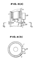
- Figures 6(a) and 6(b) show a fourth embodiment of an image pickup head according to the present invention, which is adapted to eliminate light reflected at the surface of the observed section of a subject 6 without using a liquid crystal element as used in the second embodiment.
- a first annular polarizing plate 9 located in the optical path of the projected light is fixed on a cylindrical objective contact member 7 so that its centre is aligned with the optical axis of the image pickup head, while a second polarizing plate 12 placed in the optical path of the reflected right is supported in the opening 11 of a mounting cylinder 10. It covers the opening 11 and is slidable in a direction perpendicular to the optical axis.
- the second polarizing plate 12 comprises a combination of a polarizing plate section 12a and a transparent polarizing plate section 12b.
- the polarizing section 12a allows linearly polarized light in a direction at an angle to the linearly polarized light passing through the first polarizing plate 9 to pass, while the transparent polarizing plate section 12b allows linearly polarized light in the same direction as the linearly polarized light passing through the first polarizing plate 9 to pass, or is free of any polarization properties.
- This second polarizing plate 12 has on one side a slide member 27, which is arranged so as to project or extend outside the objective contact member 7. It is constantly elastically abutted against a cam 26 driven through a motor 23 located outside a lens tube 1 by means of a spring 29.
- the use of the transparent polarizing plate section 12b permits the difference in brightness between an image accompanied by reflected light and one free of reflected light to be significantly reduced.
- the remainder of the fourth embodiment is substantially the same as the first embodiment.
- the image pickup head of the fourth embodiment light for illumination radiated from a light source (not shown) is guided through a light guide 4 to the first polarizing plate 9, where it is linearly polarized.
- the motor 23 is driven, the sections 12a and 12b of the second polarizing plate 12 are reciprocated in a plane perpendicular to the optical path of the reflected light, so that the polarizing plate sections 12a and 12b enter the optical path alternately.
- Such an arrangement causes the ratio of permeation of the linearly polarized light through the polarizing plate 9 and then reflected at the surface of the observed section of the subject 6 to be decreased, so that reflected light from which a significant proportion of the light reflected at the abutment surface of the subject is removed may be introduced to the image pickup element, resulting in an image being obtained in which the light reflected on the abutment surface is greatly reduced.
- Each of the image pickup heads of the present invention described above permits an image of a desired magnification to be obtained, determined by the magnifying optical system selected. It has been found that all the above-described embodiments allow the image to be magnified fifty to two hundred times.
- an image pickup head in accordance with the present invention selectively provides an output for the image pickup element, either accompanied by light reflected at the surface of the observed section of a subject, or substantially decreased in or free from such reflected light.
- the image pickup head of the present invention permits the outputs to be instantaneously changed.
- the present invention eliminates any necessity to keep a subject stationary, resulting in the possibility of an image of the subject accompanied by light reflected at the surface of the subject and an image decreased in or free of such reflected light being substantially simultaneously observed.
- the output for the image pickup element accompanied by light reflected at the surface of the observed section of the subject can provide an image of the surface which readily enables the observation of any unevenness of the surface, whereas the output for the image pickup element decreased in reflected light permits the colour of the surface of the subject to be distinctly and accurately observed.
- the image pickup head of the present invention allows, for example, the conditions of the skin, hair, capillary vessels of a human body, the rubescence of the skin, the precipitaion of any pigment in the skin, a change to the morbid state and the like, to be readily diagnosed.
- the present invention permits the observed section of a subject to be directly visually observed, so that the diagnosis of pigment precipitation in the skin, the diagnosis of a grey hair, the inspection of dandruff and the like may be quantitatively carried out.
- the image pickup head of the present invention is widely applicable to the inspection of fine cracks or unevenness in the surface of products in various industrial fields, for quality control of the product and the like.
Landscapes
- Physics & Mathematics (AREA)
- General Physics & Mathematics (AREA)
- Optics & Photonics (AREA)
- Astronomy & Astrophysics (AREA)
- Chemical & Material Sciences (AREA)
- Analytical Chemistry (AREA)
- Endoscopes (AREA)
- Measurement Of The Respiration, Hearing Ability, Form, And Blood Characteristics Of Living Organisms (AREA)
- Length Measuring Devices By Optical Means (AREA)
- Studio Devices (AREA)
Applications Claiming Priority (4)
| Application Number | Priority Date | Filing Date | Title |
|---|---|---|---|
| JP1026462A JPH02207401A (ja) | 1989-02-04 | 1989-02-04 | 拡大撮像装置における照明装置 |
| JP26462/89 | 1989-02-04 | ||
| JP1273419A JPH03135276A (ja) | 1989-10-20 | 1989-10-20 | 撮像装置の撮像ヘッド |
| JP273419/89 | 1989-10-20 |
Publications (3)
| Publication Number | Publication Date |
|---|---|
| EP0382424A2 true EP0382424A2 (fr) | 1990-08-16 |
| EP0382424A3 EP0382424A3 (fr) | 1992-01-02 |
| EP0382424B1 EP0382424B1 (fr) | 1996-11-20 |
Family
ID=26364248
Family Applications (1)
| Application Number | Title | Priority Date | Filing Date |
|---|---|---|---|
| EP90301109A Expired - Lifetime EP0382424B1 (fr) | 1989-02-04 | 1990-02-02 | Tête de lecture pour un dispositif de lecture d'images |
Country Status (6)
| Country | Link |
|---|---|
| US (1) | US4988158A (fr) |
| EP (1) | EP0382424B1 (fr) |
| KR (1) | KR950011887B1 (fr) |
| CN (1) | CN1016561B (fr) |
| CA (1) | CA2009129C (fr) |
| DE (1) | DE69029155T2 (fr) |
Cited By (2)
| Publication number | Priority date | Publication date | Assignee | Title |
|---|---|---|---|---|
| WO1993007522A1 (fr) * | 1991-10-11 | 1993-04-15 | L'oreal | Appareil pour observer in vivo la structure microscopique de la peau ou d'un tissu similaire |
| FR2688320A1 (fr) * | 1992-03-06 | 1993-09-10 | Micro 2000 Sa | Procede et dispositif d'eclairage d'une empreinte formee a la surface d'un materiau et application a un dispositif de controle de la durete. |
Families Citing this family (11)
| Publication number | Priority date | Publication date | Assignee | Title |
|---|---|---|---|---|
| JPH0422711U (fr) * | 1990-06-15 | 1992-02-25 | ||
| JPH04146411A (ja) * | 1990-10-09 | 1992-05-20 | Sumitomo Electric Ind Ltd | ファイバコリメータの製造方法 |
| WO1993001686A1 (fr) * | 1991-07-04 | 1993-01-21 | Scalar Corp. | Appareil d'observation grossissant |
| US5719700A (en) * | 1991-10-11 | 1998-02-17 | L'oreal | Apparatus for in vivo observation of the microscopic structure of the skin or of a similar tissue |
| DE10227209B4 (de) * | 2002-06-12 | 2005-02-17 | Tropf, Hermann, Dipl.-Ing. | Verfahren zur Aufnahme von Bildern von metallischen, teilweise flüssigkeitsbenetzten Oberflächen |
| DE10262076B4 (de) * | 2002-06-12 | 2006-01-19 | Tropf, Hermann, Dr.-Ing. | Vorrichtung zur Aufnahme von Bildern von metallischen, teilweise flüssigkeitsbenetzten Oberflächen |
| CN103620375B (zh) * | 2011-04-29 | 2016-06-29 | 西门子医疗保健诊断公司 | 高通量准直照射器和均匀场照射的方法 |
| WO2014134487A1 (fr) * | 2013-02-28 | 2014-09-04 | Canfield Scientific, Incorporated | Dispositifs de dermoscopie |
| US10078254B2 (en) * | 2014-05-14 | 2018-09-18 | Sony Corporation | Imaging device and imaging method |
| US11395714B2 (en) | 2019-11-11 | 2022-07-26 | Dermlite Llc | Medical illuminator with variable polarization |
| CN113867073B (zh) * | 2020-06-11 | 2023-07-04 | 北京小米移动软件有限公司 | 一种可变光圈模组、潜望式摄像头及电子设备 |
Family Cites Families (5)
| Publication number | Priority date | Publication date | Assignee | Title |
|---|---|---|---|---|
| DE1810536C3 (de) * | 1968-11-23 | 1971-08-26 | Optotechnik Gmbh | Ophthalmoskop |
| US4501473A (en) * | 1982-02-11 | 1985-02-26 | The United States Of America As Represented By The United States Department Of Energy | Front lighted shadowgraphic method and apparatus |
| DE3435369C2 (de) * | 1983-10-03 | 1986-06-19 | Olympus Optical Co., Ltd., Tokio/Tokyo | Endoskop |
| US4763993A (en) * | 1987-04-30 | 1988-08-16 | N-View Corporation | Liquid crystal display for projection systems |
| JPH01308527A (ja) * | 1988-06-07 | 1989-12-13 | Sukara Kk | 拡大撮像装置における照明用導光装置 |
-
1990
- 1990-02-01 CA CA002009129A patent/CA2009129C/fr not_active Expired - Fee Related
- 1990-02-02 DE DE69029155T patent/DE69029155T2/de not_active Expired - Fee Related
- 1990-02-02 EP EP90301109A patent/EP0382424B1/fr not_active Expired - Lifetime
- 1990-02-02 US US07/474,332 patent/US4988158A/en not_active Expired - Fee Related
- 1990-02-03 KR KR1019900001349A patent/KR950011887B1/ko not_active Expired - Fee Related
- 1990-02-03 CN CN90101410A patent/CN1016561B/zh not_active Expired
Cited By (3)
| Publication number | Priority date | Publication date | Assignee | Title |
|---|---|---|---|---|
| WO1993007522A1 (fr) * | 1991-10-11 | 1993-04-15 | L'oreal | Appareil pour observer in vivo la structure microscopique de la peau ou d'un tissu similaire |
| FR2682490A1 (fr) * | 1991-10-11 | 1993-04-16 | Oreal | Appareil pour observer in vivo la structure microscopique de la peau ou d'un tissu similaire. |
| FR2688320A1 (fr) * | 1992-03-06 | 1993-09-10 | Micro 2000 Sa | Procede et dispositif d'eclairage d'une empreinte formee a la surface d'un materiau et application a un dispositif de controle de la durete. |
Also Published As
| Publication number | Publication date |
|---|---|
| EP0382424B1 (fr) | 1996-11-20 |
| DE69029155D1 (de) | 1997-01-02 |
| DE69029155T2 (de) | 1997-04-10 |
| KR950011887B1 (ko) | 1995-10-11 |
| CN1016561B (zh) | 1992-05-06 |
| KR900013775A (ko) | 1990-09-06 |
| US4988158A (en) | 1991-01-29 |
| EP0382424A3 (fr) | 1992-01-02 |
| CA2009129C (fr) | 1995-02-14 |
| CN1044884A (zh) | 1990-08-22 |
| CA2009129A1 (fr) | 1990-08-04 |
Similar Documents
| Publication | Publication Date | Title |
|---|---|---|
| US4988158A (en) | Image pickup head for image pickup device | |
| US7852371B2 (en) | Autoclavable video camera for an endoscope | |
| US9069181B2 (en) | Optical imaging system and method, and aperture stop assembly and aperture element | |
| US20030045799A1 (en) | Device, system and method for observing a typological characteristic of the body | |
| JPS63294509A (ja) | 立体視内視鏡装置 | |
| JPH01308527A (ja) | 拡大撮像装置における照明用導光装置 | |
| JPH03135276A (ja) | 撮像装置の撮像ヘッド | |
| JP2016209453A (ja) | 細隙灯顕微鏡 | |
| JP3434902B2 (ja) | 視機能検査装置 | |
| US5793469A (en) | Variable distance, variable test object sight testing apparatus | |
| DE10153397A1 (de) | Vorrichtung und Verfahren zur Messung der Refraktion | |
| WO2021106244A1 (fr) | Unité optique | |
| US7289265B2 (en) | Microscope illumination intensity measuring device | |
| US5812240A (en) | Eyeball observing device having an ultrasonic detector | |
| US11209348B2 (en) | Hair observation method, phase contrast microscope system, and preparation | |
| JPH02207401A (ja) | 拡大撮像装置における照明装置 | |
| JPH0915128A (ja) | 硬度計 | |
| JP7220471B2 (ja) | マイボーム腺観察可能な細隙灯顕微鏡 | |
| JP2006101942A (ja) | 検眼システム | |
| JPH1014871A (ja) | 視力表提示装置 | |
| JP2740936B2 (ja) | 自覚的屈折力検査装置 | |
| JPH02147045A (ja) | 眼科装置 | |
| CN208876481U (zh) | 光定位装置和系统 | |
| SU1680056A1 (ru) | Устройство дл исследовани пол зрени | |
| SU1703963A1 (ru) | Оптическое устройство контрол поверхности |
Legal Events
| Date | Code | Title | Description |
|---|---|---|---|
| PUAI | Public reference made under article 153(3) epc to a published international application that has entered the european phase |
Free format text: ORIGINAL CODE: 0009012 |
|
| AK | Designated contracting states |
Kind code of ref document: A2 Designated state(s): CH DE FR GB IT LI |
|
| 17P | Request for examination filed |
Effective date: 19901206 |
|
| PUAL | Search report despatched |
Free format text: ORIGINAL CODE: 0009013 |
|
| AK | Designated contracting states |
Kind code of ref document: A3 Designated state(s): CH DE FR GB IT LI |
|
| 17Q | First examination report despatched |
Effective date: 19940415 |
|
| RAP1 | Party data changed (applicant data changed or rights of an application transferred) |
Owner name: SCALAR CORPORATION Owner name: MITSUBISHI CHEMICAL CORPORATION |
|
| GRAH | Despatch of communication of intention to grant a patent |
Free format text: ORIGINAL CODE: EPIDOS IGRA |
|
| GRAH | Despatch of communication of intention to grant a patent |
Free format text: ORIGINAL CODE: EPIDOS IGRA |
|
| GRAG | Despatch of communication of intention to grant |
Free format text: ORIGINAL CODE: EPIDOS AGRA |
|
| GRAA | (expected) grant |
Free format text: ORIGINAL CODE: 0009210 |
|
| AK | Designated contracting states |
Kind code of ref document: B1 Designated state(s): CH DE FR GB IT LI |
|
| ITF | It: translation for a ep patent filed | ||
| REG | Reference to a national code |
Ref country code: CH Ref legal event code: NV Representative=s name: TROESCH SCHEIDEGGER WERNER AG |
|
| ET | Fr: translation filed | ||
| REF | Corresponds to: |
Ref document number: 69029155 Country of ref document: DE Date of ref document: 19970102 |
|
| PLBE | No opposition filed within time limit |
Free format text: ORIGINAL CODE: 0009261 |
|
| STAA | Information on the status of an ep patent application or granted ep patent |
Free format text: STATUS: NO OPPOSITION FILED WITHIN TIME LIMIT |
|
| 26N | No opposition filed | ||
| PGFP | Annual fee paid to national office [announced via postgrant information from national office to epo] |
Ref country code: FR Payment date: 19990129 Year of fee payment: 10 |
|
| PGFP | Annual fee paid to national office [announced via postgrant information from national office to epo] |
Ref country code: GB Payment date: 19990204 Year of fee payment: 10 |
|
| PGFP | Annual fee paid to national office [announced via postgrant information from national office to epo] |
Ref country code: CH Payment date: 19990427 Year of fee payment: 10 |
|
| PGFP | Annual fee paid to national office [announced via postgrant information from national office to epo] |
Ref country code: DE Payment date: 19990429 Year of fee payment: 10 |
|
| PG25 | Lapsed in a contracting state [announced via postgrant information from national office to epo] |
Ref country code: GB Free format text: LAPSE BECAUSE OF NON-PAYMENT OF DUE FEES Effective date: 20000202 |
|
| PG25 | Lapsed in a contracting state [announced via postgrant information from national office to epo] |
Ref country code: LI Free format text: LAPSE BECAUSE OF NON-PAYMENT OF DUE FEES Effective date: 20000229 Ref country code: CH Free format text: LAPSE BECAUSE OF NON-PAYMENT OF DUE FEES Effective date: 20000229 |
|
| GBPC | Gb: european patent ceased through non-payment of renewal fee |
Effective date: 20000202 |
|
| REG | Reference to a national code |
Ref country code: CH Ref legal event code: PL |
|
| PG25 | Lapsed in a contracting state [announced via postgrant information from national office to epo] |
Ref country code: FR Free format text: LAPSE BECAUSE OF NON-PAYMENT OF DUE FEES Effective date: 20001031 |
|
| PG25 | Lapsed in a contracting state [announced via postgrant information from national office to epo] |
Ref country code: DE Free format text: LAPSE BECAUSE OF NON-PAYMENT OF DUE FEES Effective date: 20001201 |
|
| REG | Reference to a national code |
Ref country code: FR Ref legal event code: ST |
|
| PG25 | Lapsed in a contracting state [announced via postgrant information from national office to epo] |
Ref country code: IT Free format text: LAPSE BECAUSE OF NON-PAYMENT OF DUE FEES;WARNING: LAPSES OF ITALIAN PATENTS WITH EFFECTIVE DATE BEFORE 2007 MAY HAVE OCCURRED AT ANY TIME BEFORE 2007. THE CORRECT EFFECTIVE DATE MAY BE DIFFERENT FROM THE ONE RECORDED. Effective date: 20050202 |