EP0382520A2 - WC à chasse d'eau - Google Patents
WC à chasse d'eau Download PDFInfo
- Publication number
- EP0382520A2 EP0382520A2 EP90301324A EP90301324A EP0382520A2 EP 0382520 A2 EP0382520 A2 EP 0382520A2 EP 90301324 A EP90301324 A EP 90301324A EP 90301324 A EP90301324 A EP 90301324A EP 0382520 A2 EP0382520 A2 EP 0382520A2
- Authority
- EP
- European Patent Office
- Prior art keywords
- shutter
- pot
- incinerating
- drain pipe
- water
- Prior art date
- Legal status (The legal status is an assumption and is not a legal conclusion. Google has not performed a legal analysis and makes no representation as to the accuracy of the status listed.)
- Granted
Links
Images


Classifications
-
- E—FIXED CONSTRUCTIONS
- E03—WATER SUPPLY; SEWERAGE
- E03D—WATER-CLOSETS OR URINALS WITH FLUSHING DEVICES; FLUSHING VALVES THEREFOR
- E03D5/00—Special constructions of flushing devices, e.g. closed flushing system
- E03D5/016—Special constructions of flushing devices, e.g. closed flushing system with recirculation of bowl-cleaning fluid
-
- A—HUMAN NECESSITIES
- A47—FURNITURE; DOMESTIC ARTICLES OR APPLIANCES; COFFEE MILLS; SPICE MILLS; SUCTION CLEANERS IN GENERAL
- A47K—SANITARY EQUIPMENT; ACCESSORIES THEREFOR, e.g. TOILET ACCESSORIES
- A47K11/00—Closets without flushing; Urinals without flushing; Chamber pots; Chairs with toilet conveniences or specially adapted for use with toilets
- A47K11/02—Dry closets, e.g. incinerator closets
- A47K11/023—Incinerator closets
-
- E—FIXED CONSTRUCTIONS
- E03—WATER SUPPLY; SEWERAGE
- E03D—WATER-CLOSETS OR URINALS WITH FLUSHING DEVICES; FLUSHING VALVES THEREFOR
- E03D11/00—Other component parts of water-closets, e.g. noise-reducing means in the flushing system, flushing pipes mounted in the bowl, seals for the bowl outlet, devices preventing overflow of the bowl contents; devices forming a water seal in the bowl after flushing, devices eliminating obstructions in the bowl outlet or preventing backflow of water and excrements from the waterpipe
- E03D11/02—Water-closet bowls ; Bowls with a double odour seal optionally with provisions for a good siphonic action; siphons as part of the bowl
- E03D11/11—Bowls combined with a reservoir, e.g. containing apparatus for disinfecting or for disintegrating
-
- Y—GENERAL TAGGING OF NEW TECHNOLOGICAL DEVELOPMENTS; GENERAL TAGGING OF CROSS-SECTIONAL TECHNOLOGIES SPANNING OVER SEVERAL SECTIONS OF THE IPC; TECHNICAL SUBJECTS COVERED BY FORMER USPC CROSS-REFERENCE ART COLLECTIONS [XRACs] AND DIGESTS
- Y02—TECHNOLOGIES OR APPLICATIONS FOR MITIGATION OR ADAPTATION AGAINST CLIMATE CHANGE
- Y02A—TECHNOLOGIES FOR ADAPTATION TO CLIMATE CHANGE
- Y02A50/00—TECHNOLOGIES FOR ADAPTATION TO CLIMATE CHANGE in human health protection, e.g. against extreme weather
- Y02A50/30—Against vector-borne diseases, e.g. mosquito-borne, fly-borne, tick-borne or waterborne diseases whose impact is exacerbated by climate change
-
- Y—GENERAL TAGGING OF NEW TECHNOLOGICAL DEVELOPMENTS; GENERAL TAGGING OF CROSS-SECTIONAL TECHNOLOGIES SPANNING OVER SEVERAL SECTIONS OF THE IPC; TECHNICAL SUBJECTS COVERED BY FORMER USPC CROSS-REFERENCE ART COLLECTIONS [XRACs] AND DIGESTS
- Y10—TECHNICAL SUBJECTS COVERED BY FORMER USPC
- Y10S—TECHNICAL SUBJECTS COVERED BY FORMER USPC CROSS-REFERENCE ART COLLECTIONS [XRACs] AND DIGESTS
- Y10S4/00—Baths, closets, sinks, and spittoons
- Y10S4/19—Liquid-solid separators
Definitions
- the present invention relates to a flush toilet which can easily incinerate raw sewage.
- First method is impounding sewage in a sewage reservoir in each house and periodically clipping it up by a tank truck for collecting sewage in order to convey to a sewage disposal facility.
- Second method is conveying raw sewage with water from each house to a sewage disposal facility via a sewer system. This method has especially adopted in urban area.
- And third method is impounding raw sewage in a septic tank to purify raw sewage by microorganisms such as bacteria.
- a bad smell will be emitted, so the neighbors will feel uncomfortable when raw sewage is clipped up from the reservoir.
- the tank truck is required to periodially go rounds houses so as to clip sewage up at each house, so that a large amount of cost including labor cost and maintenance cost of the tank truck is required. Additionally, impounding raw sewage in the reservoir the uncomfortable bad smell is always emitted in and around the toilet.
- raw sewage can be conveyed to the sewage disposal facility with much water via the sewer system.
- Raw sewage conveyed is dealt by various ways in the facility. For example, raw sewage is disintegrated by adding chemicals, heating, pressurizing or using bacteria. Supernatant water introduced into a settling pond is chlorinated, and then is discharge to a river. While, sludge deposited in the pond is incinerated or is used for filling up land after dehydrating. The cost of this method will be huge, and uncomfortable and bad smell is emitted in and around the facility. Conditions of the location of the facility is limited.
- raw sewage is fermented and disintegrated by bacteria but a large amount of water is required.
- bacteria's activity is weakend so that amount of disintegration is reduced.
- Water purified is percolated in the ground through a filter but the filter gets clogged when water purification is imperfection.
- water and raw sewage should be clipped up by the tank truck in order to convey them to the sewage disposal facility.
- amount of raw sewage often beyonds capacity of a septic tank when many tourists come, so that raw sewage half disintegrated runs over the tank.
- the main object of the present invention is to provide a flush toilet, which can easily incinerate sewage and which can reuse water once flushed by filtering.
- the flush toilet of the present invention comprises an incinerating pot for incinerating sewage, etc. arranged below a toilet stool, a drain pipe vertically connecting the incinerating pot and the toilet stool, a shutter arranged in the midway of the drain pipe, the shutter opens the drain pipe during evacuation or urination and closes after completing evacuation or urination, and a branch pipe attached to the drain pipe above the shutter in order to introduce water flushed apart from sewage, etc.
- the flush toilet may have two shutters. They are a first shutter arranged in the midway of the drain pipe, the first shutter opens the drain pipe during evacuation or urination and closes after completing evacuation or urination, and a second shutter arranged in the midway of the drain pipe and below the first shutter, the second shutter closes the drain pipe while the first shutter closes the drain pipe and opens the drain pipe when the first shutter closes the drain pipe.
- the flush toilet may have the structure that the branch pipe is connected to a filtering apparatus, and the toilet stool and a tank for impounding water filterd by the filtering apparatus are connected each other by a return pipe.
- the flush toilet may have the incinerating pot whose inner center part is formed lower, and may further comprise a fan for agitating sewage, etc. in the incinerating pot and means for sucking ash, whose lower end is arranged in the incinerating pot.
- the flush toilet may further comprise means for introducing garbage, etc. besides sewage into the incinerating pot, whereby garbage, etc. can be incinerated with or without sewage.
- the flush toilet of the present invention with above stated structure has following advantages.
- Raw sewage, etc. can be easily directed to the incinerating pot because the incinerating pot is arranged under the toilet stool.
- Raw sewage, etc. and flush water can be dealt separately because the shutter or shutters are provided in the midway of the drain pipe and the branch pipe is arranged above the shutter or shutters.
- the first shutter opens, and after evacuation or urination, the first shutter closes and then the second shutter opens to direct raw sewage onto the incinerating pot. Additionally, flushing water can be flushed only the case that the first shutter is closed. Therefore, even though the first shutter opens during incineration, the second shutter prevents emitting heat and/or bad smell.
- water flushed may be filtered, so that the water filtered can be reused as flushing water. This is effective and economical.
- kitchen garbage, etc. also can be incinerated with or without sewage.
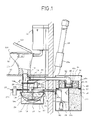
- Fig. 1 shows a schematic view of the flush toilet of the present invention.
- a toilet stool 10 has a seat section 11a and a cover section 11b.
- the toilet stool 10 is set on a floor 12.
- the incinerating pot 14 and the toilet stool 12 is connected by a vertical drain pipe 16.
- the first and second shutters 18a and 18b are respectively able to open and close the drain pipe 16 by actuators 20a and 20b. If the seat section 11a or the cover section 11b is lifted, the actuator 20a is driven by known electrical means to open the first shutter 18a, so that the drain pipe 16 lets through. There is provided a control section on the toilet stool 10. After evacuation or urination, the control section 11c is operated, so that the first shutter 18a is closed and then the second shutter 18b is opened by another known electrical means.
- an electric heater 13 immediately below the bottom face of the hemispherical pot proper 14a.
- the electric heater 13 is covered with a hemispherical reflector 14b so as to reflect heat from the electric heater 13 toward the pot proper 14a.
- the opening of the pot proper 14a is covered with a lid 15.
- Fig. 2 shows a plan view of the incinerating pot 14.
- the lid 15 of the incinerating pot 14 has three openings.
- the first opening 15a is connected to the drain pipe 16.
- the second opening 15b is connected to a smokestack 23.
- the third opening 15c may be connected to a pipe through which garbage can be introduced into the pot proper 14a.
- the lid 15 has a check hole 15d, and can be opened or closed by hand with gripping a handle 15e.
- a pulley 26a is fixed at the upper section of the drive shaft 26 which is projected upward from the lid 15.
- the pully 26a is connected to a pulley 24a, which is fixed at a shaft of a motor 24 adjacent to the incinerating pot 14, by a belt 25.
- a fan 28 At the lower end of the drive shaft 26 is a fan 28.
- the fan 28 agitates raw sewage in the incinerating pot 14 for efficient incineration, so the fan 28 is formed along the inner face of the incinerating pot 14.
- the drive shaft 26 is cylindrical and its lower end is opened. While, a joint 29 is fixed at the top end of the drive shaft 26. The joint 29 does not rotate with the rotation of the drive shaft 26.
- the joint 29 and a sucking apparatus 30 are connected each other by a pipe 31, so that ash in the incinerating pot 14 is drew into the sucking apparatus 30 via the drive shaft 26, the joint 29 and the pipe 31.
- the drive shaft 26 serves as not only a drive shaft but also a sucking pipe. Therefore, ash of sewage burnt in the incinerating pot 14 is collected by the fan 28 and sucked to the sucking apparatus 30 from the lower end of the drive shaft 26.
- a deodorizing section 23a at the midway of the smokestack 23.
- the deodorizing section 23a has deodorizer (not shown) in order to eliminate bad smell in smoke.
- a branch pipe 32 is connected to the drain pipe 16.
- the front end of the branch pipe 32 is connected to a filtering apparatus 34.
- the filtering apparatus 34 has a first filtering tank 36 for filtering water from the branch pipe 32 and a second filtering tank 38 accommodated in the first filtering tank 36.
- Figs. 3 and 4 are plan views of part of the filtering apparatus.
- the first filtering tank 36 is formed like shallow cylindrical shape and has multiple through-holes in the wall. There is provided a cup-like receiving section 40 at the center of the first filtering tank 36. The front end of the branch pipe 32 reaches to the raceiving section 40.
- the receiving section 40 is supported by deodorizers 42a.
- the deodorizers 42a are accommodated in a deodorizer chamber 42 which is divided by a cylindrical parting member 44 having multiple through-holes.
- filtering materials 46a such as charcoal, sand, etc. are accommodated therein. Water introduced by the branch pipe 32 is impounded in the receiving section 40 and overflows.
- the water flows into the deodorizer chamber 42 and the filtering chamber 46 via the through-holes of the parting member 44.
- the water which has been filtered by the filtering materials 46a in the filtering chamber 46, flows out from the wall of the first filtering tank 36.
- the diameter of the second filtering tank 38 is larger than the diameter of the first filteing tank 36, so that the first filtering tank 36 is accommodated in the second filtering tank 38.
- the first filtering tank 36 is supported by a first parting plate 52, which connects the outer fringe section of the bottom face of the first filtering tank 36 and the inner wall face of the second filtering tank 38.
- a part of the first parting plate 52 is opened as an exit 54.
- the first parting plate 52 is inclined in order that the position of the exit 54 should be low. Deodorizers are on the first parting plate 52.
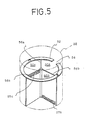
- the second filtering tank 38 is divided into three chambers by radially arranged second parting plates 56a, 56b and 56c.
- a first filtering chamber 50A which is formed by the second parting plates 56a and 56b, is connected to the exit 54.
- the chamber formed by the second parting plates 56b and 56c is a tank 50c for impounding water filtered.
- the first filtering chamber 50A and the second filtering chamber 50B are connected by multiple through-holes 57b..., which are bored in the lower section of the second parting plate 56b.
- water introduced in the first filtering chamber 50A via the exit 54 is filtered in the first filtering chamber 50A and flows into the second filtering chamber 50B via the through-holes 57b... of the second parting plate 56b.
- Fig. 5 shows the arrangement of the second parting plates 56a, 56b and 56c of the second filtering tank 38 and the first parting plate 52.
- the tank 50c and the flash tank 11 are connected each other by a return pipe 58.
- the front end of the return pipe 58 is connected to a pump 60, which is provided in the tank 50c.
- the pump 60 introduces the water filtered into the flush tank 11.
- overflow-pipe 62 in the tank 50c.
- the front end of the overflow-pipe 62 is formed U-shape as a trap 62a.
- the rear end of the overflow-pipe 62 is connected to the incinerating pot 14 for introducing water overflowed into the incinerating pot 14.
- the first shutter 18a is clipped by clipping plates 21 and 22.
- the lower clipping plate 21 has a cavity 21a having walls on three sides; one side is opened. There is bored a hole 21b in the bottom of the cavity 21a.
- a connecting pipe 21c is connected to the hole 21b and extended downward.
- the first shutter 18a in the cavity 21a can be slided toward the open side of the cavity 21a.
- the open side of the cavity 21a of the clipping plate 21 is fixed to a fixed member 64.
- An actuator 20a is fixed outside of the fixed member 64.
- a screw rod 19 is pierced through the fixed member 64 and the actuator 20a, and the first shutter 18a is rotatably attached to the front end of the screw rod 19.
- a gear engaging with a motor for driving the screw rod 19 is accommodated in the actuator 20a. Namely, the first shutter 18a can be moved back and forth depending on the rotational direction of the screw rod 19 to open and to close the drain pipe 16.
- a sealing member 17a is fixed in a groove, which is coaxially grooved to the hole 21b in the cavity 21a.
- Another sealing member 17b whose length is the same as the width of the carvity 21a, is fixed to the open side of the cavity 21a.
- a groove 21e is grooved from the corner of the cavity 21a to the hole 21b. The groove 21e and the hole 21b is connected each other.
- the clipping plate 22 covering over the cavity 21a of the clipping plate 21 is fixed on the upper face of the clipping plate 21 by screw, etc. While, the clipping plate 22 has a hole 22b, which is bored at the position corresponding to the hole 21b of the clipping plate 21. A connecting pipe 22c is connected to the hole 22b and extended upward. A sealing member 17c is coaxially fixed to the hole 22b (see Figs. 8 and 9).
- the clipping plate 22 is piled on the clipping plate 21 to form a slidable mechanism of the first shutter 18a. Note that, a groove 22d is grooved on the bottom face of the clipping plate 22. The screw rod 19 can be moved in the groove 22d.
- An opening 22f is opened at the fixed member 64 side of the clipping plate 22.
- the drain pipe 16 is connected to connecting sections 21c and 22c of the clipping plates 21 and 22 (see Figs. 8 and 9).
- Water on the first shutter 18a is normally prevented from leaking outside of the sealing member. Even though water leaks outside thereof, the water is introduced to the hole 21b via the groove 21e.
- Fig. 10 shows another embodiment without the flush tank 11 of the former embodiment.
- the return pipe 58 which is extended from the tank 50c of the filtering apparatus 34 is directly connected to the toilet stool 10 in order to return the water for flushing toilet stool 10.
- flushing water is introduced back by pump 60 when the toilet stool 10 is flushed.
- This embodiment has an advantage that necessary area in the toilet can be smaller. Note that, water for washing user's anal region should be supplied from the water supply system, and if water in the tank 50c is reduced, water should be supplied by proper means such as water supply system.
- the first shutter 18a and the second shutter 18b are arranged to face each other but both shutters 18a and 18b and both actuators 20a and 20b may be arranged above the incinerating pot 14 as shown in Fig. 11 then the necessary space can be reduced.
- the fan 28 is fixed at the lower end of the drive shaft 26 but the lower end of the drive shaft 26 may be formed as shown in Fig. 12 to serve as fan and sucking mouth. In this case, the lower end of the drive shaft 26 should be slightly separate from the inner bottom face of the pot proper 14a.
- a shallow discharge groove 21f on the bottom face of the groove 21d of the cavity 21a of the clipping plate 21 clipping the shutter in order to discharge water leaked over the sealing member 17b.
- the discharge groove 21f is formed, as shown in Fig. 13, until the hole 21b via position below the sealing members 17a and 17b. With this structure, the water leaked will be discharged to the hole 21b via the discharge groove 21f. Note that, the discharge can be smooth if the carvity 21a is inclined toward the groove 21d.
- the deodorizing section 23a has deodorizers therein.
- Electric heater may be used for deodorization.
- a heat reflector 68 having lower and upper projections for reducing diameter of the smokestack 23 is attached to the mid section of the smokestack 23 and for reflecting heat from heaters 69....
- the electric heaters 69... are spanned between tops of the lower and upper projections.
- the heaters 69... are rounded by a plate with through-holes with this structure, smoke climbing through the smokestack 23 can be completely combusted, so that no bad smell will be emitted.
- single filtering apparatus 34 is provided to single incinerating pot 14.
- a plurality of toilet stools are set in a hotel.
- a plurality of incinating pots 14 are provided to each of toilet stools 10 but single filtering apparatus 34 may be provided for a plurality of incinerating pots 14.
- FIGs. 16 and 17 show a part of kitchen beside the toilet.
- a cupboard 72 is arranged beside a sink 70.
- An upper end of the pipe 74 is opened in the upper face of the cupboard 72; the lower end of the pipe 74 is connected to the third opening 15c of the incinerating pot 14.
- Two shutters 76a and 76b are provided at the midway of the pipe 74.
- the first shutter 76a and second shutter 76b are respectively driven by a first actuator 78a and a second actuator 78b to close and to open the pipe 74.
- the structure and interconnection of the shutters 76a and 76b and actuators 20a and 20b are the same as the structure and interconnection of the shutters 18a and 18b and the actuators 20a and 20b of the former embodiment.
- the first actuator 78a When garbage is thrown into the incinerating pot 14, the first actuator 78a is operated to open the first shutter 76a. After garbage is thrown into the pipe 74, the first shutter 76a is closed and then the second shutter 76b is opened so as to introduce garbage onto the incinerating pot 14. Garbage can be incinerated with sewage in the incinerating pot 14. Note that, the incinerating pot 14 can incinerate only sewage, only garbage, or the both.
- Raw sewage can be easily directed to the incinerating pot because the incinerating pot is arranged under the toilet stool.
- Raw sewage and flush water can be dealt separately because the shutters are provided in the midway of the drain pipe and the branch pipe is provided above the shutters.
- the first shutter opens, and after evacuation or urination, the first shutter closes and then the second shutter opens to fall raw sewage onto the incinerating pot. Additionally, flushing water can be flushed only the case that the first shutter is closed. Therefore, even if the first shutter opens during incineration, the second shutter prevents emitting heat or bad smell.
- water flushed may be filtered, so that the water filtered can be reused as flushing water. This method is effective and economical.
Landscapes
- Health & Medical Sciences (AREA)
- Public Health (AREA)
- Engineering & Computer Science (AREA)
- Life Sciences & Earth Sciences (AREA)
- Hydrology & Water Resources (AREA)
- Water Supply & Treatment (AREA)
- Aviation & Aerospace Engineering (AREA)
- Sanitary Device For Flush Toilet (AREA)
- Non-Flushing Toilets (AREA)
- Vehicle Waterproofing, Decoration, And Sanitation Devices (AREA)
- Bidet-Like Cleaning Device And Other Flush Toilet Accessories (AREA)
Applications Claiming Priority (2)
| Application Number | Priority Date | Filing Date | Title |
|---|---|---|---|
| JP32493/89 | 1989-02-10 | ||
| JP3249389 | 1989-02-10 |
Publications (3)
| Publication Number | Publication Date |
|---|---|
| EP0382520A2 true EP0382520A2 (fr) | 1990-08-16 |
| EP0382520A3 EP0382520A3 (en) | 1990-10-10 |
| EP0382520B1 EP0382520B1 (fr) | 1993-12-08 |
Family
ID=12360519
Family Applications (1)
| Application Number | Title | Priority Date | Filing Date |
|---|---|---|---|
| EP90301324A Expired - Lifetime EP0382520B1 (fr) | 1989-02-10 | 1990-02-08 | WC à chasse d'eau |
Country Status (10)
| Country | Link |
|---|---|
| US (1) | US5068926A (fr) |
| EP (1) | EP0382520B1 (fr) |
| JP (1) | JPH0826570B2 (fr) |
| KR (1) | KR950003004B1 (fr) |
| AT (1) | ATE98103T1 (fr) |
| AU (1) | AU620496B2 (fr) |
| CA (1) | CA2009568C (fr) |
| DE (1) | DE69004988T2 (fr) |
| DK (1) | DK0382520T3 (fr) |
| ES (1) | ES2048424T3 (fr) |
Cited By (2)
| Publication number | Priority date | Publication date | Assignee | Title |
|---|---|---|---|---|
| CN1085000C (zh) * | 1994-03-02 | 2002-05-15 | 惠普公司 | 用细微的点打印n-色调图象 |
| WO2007114747A1 (fr) * | 2006-03-30 | 2007-10-11 | Christopher Nilsen | Toilette a incinerateur |
Families Citing this family (25)
| Publication number | Priority date | Publication date | Assignee | Title |
|---|---|---|---|---|
| JP2683522B2 (ja) * | 1990-12-19 | 1997-12-03 | 株式会社レンタルのニッケン | 屎尿処理装置 |
| US6081940A (en) * | 1999-06-11 | 2000-07-04 | Nien; Chin-Fu | Non-flushing toilet |
| JP2001336195A (ja) * | 2000-05-29 | 2001-12-07 | Emutekusu:Kk | 加熱蒸発式トイレ装置 |
| WO2002066752A1 (fr) * | 2001-02-16 | 2002-08-29 | Semco Vakuumteknik A/S | Desintegrateur pour w.c. |
| KR20030040611A (ko) * | 2001-11-15 | 2003-05-23 | 박방열 | 절수형·저 소음형 변기 |
| KR20030011027A (ko) * | 2002-10-25 | 2003-02-06 | 권영식 | 수세식 변기 |
| KR20040038574A (ko) * | 2002-11-01 | 2004-05-08 | 한갑용 | 물탱크를 이용한 세척 및 냉각수단을 갖는 인체배설물용자동소각장치 |
| US8266739B2 (en) * | 2003-12-01 | 2012-09-18 | Jerry D. Thom | Remote-controlled vehicle for transporting bio-waste |
| US20050210573A1 (en) * | 2003-12-01 | 2005-09-29 | Schaaf Vincent P | Train-operated biowaste removal system |
| US11206959B2 (en) | 2003-12-01 | 2021-12-28 | Jerry D. Thom | Systems and methods for transporting bio-waste |
| KR100752578B1 (ko) * | 2005-09-16 | 2007-08-29 | 강광호 | 화장실 |
| KR100753961B1 (ko) * | 2006-02-14 | 2007-09-03 | 최호찬 | 소음예방 및 절수형 소, 대변기 |
| KR100859753B1 (ko) * | 2006-09-01 | 2008-09-24 | 문상훈 | 수세식 변기 및 사이클론식 정화장치 |
| CN101824848A (zh) * | 2009-03-05 | 2010-09-08 | 郑亚蓉 | 双排污管节水坐便器 |
| US20130167293A1 (en) * | 2010-07-16 | 2013-07-04 | Masayuki Nakaya | Temporary toilet |
| KR101110615B1 (ko) * | 2011-04-07 | 2012-02-29 | 박상욱 | 화장실 분뇨 처리 및 유기질 비료제조 장치 |
| BR112014002565A2 (pt) * | 2011-08-02 | 2017-06-06 | Paulee Cleantec Ltd | aparelho de vaso sanitário e método para descartar e esterilizar os dejetos |
| US9651250B2 (en) | 2014-11-03 | 2017-05-16 | Jerry Thom | Systems and methods for transporting and collecting bio-waste |
| CN106193230B (zh) * | 2016-08-05 | 2018-05-01 | 京东方科技集团股份有限公司 | 智能马桶、智能马桶的运行控制方法及装置 |
| CN108130945B (zh) * | 2018-02-12 | 2025-02-18 | 陈钦先 | 一种循环储水便器之顶针过滤式冲洗给水装置 |
| NO344433B1 (en) * | 2018-04-16 | 2019-12-09 | Cinderella Tech As | Incinerating toilet with a lifting device |
| US10669706B2 (en) | 2018-04-20 | 2020-06-02 | 3S Renovations, LLC | Toilet assemblies |
| US11912213B2 (en) * | 2018-05-01 | 2024-02-27 | Thetford Bv | Discharge device for vehicle wastewater management system |
| CN111533409A (zh) * | 2020-05-12 | 2020-08-14 | 兰州华能生态能源科技股份有限公司 | 一种生态水厕化粪池防沉降结构 |
| GB2610191B (en) * | 2021-08-24 | 2024-02-28 | Univ Cranfield | Soild waste processing apparatus |
Family Cites Families (14)
| Publication number | Priority date | Publication date | Assignee | Title |
|---|---|---|---|---|
| DE47788C (de) * | Dr. G. GEHRING, rechtskundiger Bürgermeister in Landshut, Bayern | Abortanlage mit getrennter Abführung der festen und flüssigen Abgangsstoffe | ||
| US3474468A (en) * | 1967-12-18 | 1969-10-28 | Ernest Bayne Blankenship | Incinerator toilet using water |
| US3673614A (en) * | 1970-12-21 | 1972-07-04 | Chrysler Corp | Sewage disposal system with reusable flush medium |
| US3816857A (en) * | 1971-04-16 | 1974-06-18 | J West | Incinerating commode |
| US3733617A (en) * | 1971-07-23 | 1973-05-22 | C Bennett | Disposal system for human waste |
| US4070714A (en) * | 1974-02-27 | 1978-01-31 | Monogram Industries, Inc. | Sewerless recirculating toilet and human waste storage system |
| US3995328A (en) * | 1974-12-13 | 1976-12-07 | The Boeing Company | Vacuum toilet system |
| US4040956A (en) * | 1976-06-07 | 1977-08-09 | Gulf Research & Development Company | Synthetic flush fluids |
| US4161792A (en) * | 1976-11-03 | 1979-07-24 | The Standard Products Company | Waste disposal system and method |
| JPS55107296U (fr) * | 1979-01-22 | 1980-07-26 | ||
| US4222130A (en) * | 1979-01-29 | 1980-09-16 | Inca-One Corporation | Waterless flush toilet system |
| US4561132A (en) * | 1983-03-14 | 1985-12-31 | Lew Hyok S | Air-vac toilet |
| US4546502A (en) * | 1983-03-14 | 1985-10-15 | Lew Hyok S | Evaporative waste disposal system |
| JPS63315016A (ja) * | 1987-06-18 | 1988-12-22 | 有限会社 シグナス工業 | 汚水,汚物の処理装置付トイレ |
-
1990
- 1990-02-02 US US07/474,337 patent/US5068926A/en not_active Expired - Fee Related
- 1990-02-08 CA CA002009568A patent/CA2009568C/fr not_active Expired - Fee Related
- 1990-02-08 EP EP90301324A patent/EP0382520B1/fr not_active Expired - Lifetime
- 1990-02-08 DK DK90301324.1T patent/DK0382520T3/da active
- 1990-02-08 DE DE69004988T patent/DE69004988T2/de not_active Expired - Fee Related
- 1990-02-08 ES ES90301324T patent/ES2048424T3/es not_active Expired - Lifetime
- 1990-02-08 AT AT90301324T patent/ATE98103T1/de not_active IP Right Cessation
- 1990-02-09 AU AU49701/90A patent/AU620496B2/en not_active Ceased
- 1990-02-09 JP JP2030917A patent/JPH0826570B2/ja not_active Expired - Fee Related
- 1990-02-09 KR KR1019900001608A patent/KR950003004B1/ko not_active Expired - Fee Related
Cited By (2)
| Publication number | Priority date | Publication date | Assignee | Title |
|---|---|---|---|---|
| CN1085000C (zh) * | 1994-03-02 | 2002-05-15 | 惠普公司 | 用细微的点打印n-色调图象 |
| WO2007114747A1 (fr) * | 2006-03-30 | 2007-10-11 | Christopher Nilsen | Toilette a incinerateur |
Also Published As
| Publication number | Publication date |
|---|---|
| ES2048424T3 (es) | 1994-03-16 |
| CA2009568A1 (fr) | 1990-08-10 |
| DK0382520T3 (da) | 1994-04-11 |
| US5068926A (en) | 1991-12-03 |
| JPH0826570B2 (ja) | 1996-03-13 |
| EP0382520A3 (en) | 1990-10-10 |
| DE69004988D1 (de) | 1994-01-20 |
| DE69004988T2 (de) | 1994-05-19 |
| AU4970190A (en) | 1990-08-16 |
| CA2009568C (fr) | 1993-09-07 |
| EP0382520B1 (fr) | 1993-12-08 |
| ATE98103T1 (de) | 1993-12-15 |
| AU620496B2 (en) | 1992-02-20 |
| JPH02289729A (ja) | 1990-11-29 |
| KR900013163A (ko) | 1990-09-03 |
| KR950003004B1 (ko) | 1995-03-29 |
Similar Documents
| Publication | Publication Date | Title |
|---|---|---|
| EP0382520B1 (fr) | WC à chasse d'eau | |
| US3840907A (en) | Compost toilet | |
| KR100892862B1 (ko) | 간이 이동식 화장실 | |
| US1401182A (en) | Apparatus for treating sewage | |
| CN101454248B (zh) | 卫生间人类排泄物干燥装置 | |
| NZ530182A (en) | Toilet system | |
| JPH1121972A (ja) | 移動式トイレ | |
| CN211793551U (zh) | 一种多功能全自动猫厕所 | |
| US9556602B2 (en) | Self-contained oil flush toilet unit and sewage treatment system for separating and pre-treating waste | |
| JP3448423B2 (ja) | 移動式ユニットトイレ | |
| CN2827242Y (zh) | 一种太阳能堆肥厕所 | |
| KR100441034B1 (ko) | 화장실의 인체 배설물 자동 소각장치 | |
| JP2997398B2 (ja) | トイレ装置 | |
| JP4174845B2 (ja) | 循環式便器 | |
| CN208471839U (zh) | 生活污水处理装置 | |
| JP2577441Y2 (ja) | トイレ | |
| JP2866239B2 (ja) | 汚物処理装置および処理方法 | |
| CN215227138U (zh) | 一种可保证通风除臭效果的环保旱厕 | |
| JPH06261840A (ja) | トイレ装置 | |
| CN213940588U (zh) | 引流式固液分离器 | |
| JP3023324U (ja) | 可搬式多人数用全自動水洗焼却便所 | |
| JPH10131258A (ja) | 水洗トイレ装置 | |
| JPH04174143A (ja) | 小便器ユニツトを用いたシステムトイレ | |
| CN211093697U (zh) | 一种智能化户用无水冲马桶 | |
| JPS572915A (en) | Incineration type toilet for continuous use |
Legal Events
| Date | Code | Title | Description |
|---|---|---|---|
| PUAI | Public reference made under article 153(3) epc to a published international application that has entered the european phase |
Free format text: ORIGINAL CODE: 0009012 |
|
| AK | Designated contracting states |
Kind code of ref document: A2 Designated state(s): AT BE CH DE DK ES FR GB GR IT LI LU NL SE |
|
| PUAL | Search report despatched |
Free format text: ORIGINAL CODE: 0009013 |
|
| AK | Designated contracting states |
Kind code of ref document: A3 Designated state(s): AT BE CH DE DK ES FR GB GR IT LI LU NL |
|
| 17P | Request for examination filed |
Effective date: 19901210 |
|
| 17Q | First examination report despatched |
Effective date: 19920805 |
|
| GRAA | (expected) grant |
Free format text: ORIGINAL CODE: 0009210 |
|
| AK | Designated contracting states |
Kind code of ref document: B1 Designated state(s): AT BE CH DE DK ES FR GB GR IT LI LU NL SE |
|
| REF | Corresponds to: |
Ref document number: 98103 Country of ref document: AT Date of ref document: 19931215 Kind code of ref document: T |
|
| REF | Corresponds to: |
Ref document number: 69004988 Country of ref document: DE Date of ref document: 19940120 |
|
| ITF | It: translation for a ep patent filed | ||
| REG | Reference to a national code |
Ref country code: ES Ref legal event code: FG2A Ref document number: 2048424 Country of ref document: ES Kind code of ref document: T3 |
|
| ET | Fr: translation filed | ||
| EPTA | Lu: last paid annual fee | ||
| REG | Reference to a national code |
Ref country code: DK Ref legal event code: T3 |
|
| REG | Reference to a national code |
Ref country code: GR Ref legal event code: FG4A Free format text: 3010981 |
|
| PLBE | No opposition filed within time limit |
Free format text: ORIGINAL CODE: 0009261 |
|
| STAA | Information on the status of an ep patent application or granted ep patent |
Free format text: STATUS: NO OPPOSITION FILED WITHIN TIME LIMIT |
|
| 26N | No opposition filed | ||
| EAL | Se: european patent in force in sweden |
Ref document number: 90301324.1 |
|
| PGFP | Annual fee paid to national office [announced via postgrant information from national office to epo] |
Ref country code: SE Payment date: 19970203 Year of fee payment: 8 |
|
| PGFP | Annual fee paid to national office [announced via postgrant information from national office to epo] |
Ref country code: ES Payment date: 19970210 Year of fee payment: 8 |
|
| PGFP | Annual fee paid to national office [announced via postgrant information from national office to epo] |
Ref country code: BE Payment date: 19970214 Year of fee payment: 8 |
|
| PGFP | Annual fee paid to national office [announced via postgrant information from national office to epo] |
Ref country code: AT Payment date: 19970217 Year of fee payment: 8 |
|
| PGFP | Annual fee paid to national office [announced via postgrant information from national office to epo] |
Ref country code: CH Payment date: 19970225 Year of fee payment: 8 |
|
| PGFP | Annual fee paid to national office [announced via postgrant information from national office to epo] |
Ref country code: DK Payment date: 19970227 Year of fee payment: 8 Ref country code: DE Payment date: 19970227 Year of fee payment: 8 |
|
| PGFP | Annual fee paid to national office [announced via postgrant information from national office to epo] |
Ref country code: NL Payment date: 19970228 Year of fee payment: 8 |
|
| PGFP | Annual fee paid to national office [announced via postgrant information from national office to epo] |
Ref country code: LU Payment date: 19970408 Year of fee payment: 8 |
|
| PGFP | Annual fee paid to national office [announced via postgrant information from national office to epo] |
Ref country code: GB Payment date: 19980129 Year of fee payment: 9 |
|
| PG25 | Lapsed in a contracting state [announced via postgrant information from national office to epo] |
Ref country code: LU Free format text: LAPSE BECAUSE OF NON-PAYMENT OF DUE FEES Effective date: 19980208 Ref country code: AT Free format text: LAPSE BECAUSE OF NON-PAYMENT OF DUE FEES Effective date: 19980208 |
|
| PG25 | Lapsed in a contracting state [announced via postgrant information from national office to epo] |
Ref country code: SE Free format text: LAPSE BECAUSE OF NON-PAYMENT OF DUE FEES Effective date: 19980209 Ref country code: ES Free format text: LAPSE BECAUSE OF EXPIRATION OF PROTECTION Effective date: 19980209 |
|
| PGFP | Annual fee paid to national office [announced via postgrant information from national office to epo] |
Ref country code: GR Payment date: 19980212 Year of fee payment: 9 |
|
| PGFP | Annual fee paid to national office [announced via postgrant information from national office to epo] |
Ref country code: FR Payment date: 19980217 Year of fee payment: 9 |
|
| PG25 | Lapsed in a contracting state [announced via postgrant information from national office to epo] |
Ref country code: LI Free format text: LAPSE BECAUSE OF NON-PAYMENT OF DUE FEES Effective date: 19980228 Ref country code: CH Free format text: LAPSE BECAUSE OF NON-PAYMENT OF DUE FEES Effective date: 19980228 Ref country code: BE Free format text: LAPSE BECAUSE OF NON-PAYMENT OF DUE FEES Effective date: 19980228 |
|
| PG25 | Lapsed in a contracting state [announced via postgrant information from national office to epo] |
Ref country code: DK Free format text: LAPSE BECAUSE OF NON-PAYMENT OF DUE FEES Effective date: 19980302 |
|
| BERE | Be: lapsed |
Owner name: SUZUKI KANEYUKI Effective date: 19980228 |
|
| PG25 | Lapsed in a contracting state [announced via postgrant information from national office to epo] |
Ref country code: NL Free format text: LAPSE BECAUSE OF NON-PAYMENT OF DUE FEES Effective date: 19980901 |
|
| REG | Reference to a national code |
Ref country code: CH Ref legal event code: PL |
|
| EUG | Se: european patent has lapsed |
Ref document number: 90301324.1 |
|
| NLV4 | Nl: lapsed or anulled due to non-payment of the annual fee |
Effective date: 19980901 |
|
| PG25 | Lapsed in a contracting state [announced via postgrant information from national office to epo] |
Ref country code: DE Free format text: LAPSE BECAUSE OF NON-PAYMENT OF DUE FEES Effective date: 19981103 |
|
| PG25 | Lapsed in a contracting state [announced via postgrant information from national office to epo] |
Ref country code: GB Free format text: LAPSE BECAUSE OF NON-PAYMENT OF DUE FEES Effective date: 19990208 |
|
| PG25 | Lapsed in a contracting state [announced via postgrant information from national office to epo] |
Ref country code: GR Free format text: LAPSE BECAUSE OF NON-PAYMENT OF DUE FEES Effective date: 19990228 |
|
| GBPC | Gb: european patent ceased through non-payment of renewal fee |
Effective date: 19990208 |
|
| PG25 | Lapsed in a contracting state [announced via postgrant information from national office to epo] |
Ref country code: FR Free format text: LAPSE BECAUSE OF NON-PAYMENT OF DUE FEES Effective date: 19991029 |
|
| REG | Reference to a national code |
Ref country code: FR Ref legal event code: ST |
|
| REG | Reference to a national code |
Ref country code: DK Ref legal event code: EBP |
|
| REG | Reference to a national code |
Ref country code: ES Ref legal event code: FD2A Effective date: 20000601 |
|
| PG25 | Lapsed in a contracting state [announced via postgrant information from national office to epo] |
Ref country code: IT Free format text: LAPSE BECAUSE OF NON-PAYMENT OF DUE FEES Effective date: 20050208 |