EP0382959A2 - Aufzeichnungs- und Wiedergabegerät für digitale Signale - Google Patents
Aufzeichnungs- und Wiedergabegerät für digitale Signale Download PDFInfo
- Publication number
- EP0382959A2 EP0382959A2 EP89301507A EP89301507A EP0382959A2 EP 0382959 A2 EP0382959 A2 EP 0382959A2 EP 89301507 A EP89301507 A EP 89301507A EP 89301507 A EP89301507 A EP 89301507A EP 0382959 A2 EP0382959 A2 EP 0382959A2
- Authority
- EP
- European Patent Office
- Prior art keywords
- standard
- recording
- digital signal
- playback
- rotary drum
- Prior art date
- Legal status (The legal status is an assumption and is not a legal conclusion. Google has not performed a legal analysis and makes no representation as to the accuracy of the status listed.)
- Granted
Links
- 230000005236 sound signal Effects 0.000 claims description 7
- 230000015572 biosynthetic process Effects 0.000 claims 1
- 239000013598 vector Substances 0.000 description 38
- 238000010586 diagram Methods 0.000 description 15
- 230000000694 effects Effects 0.000 description 4
- 230000006870 function Effects 0.000 description 3
- 230000004044 response Effects 0.000 description 3
- 238000010276 construction Methods 0.000 description 2
- 230000002093 peripheral effect Effects 0.000 description 2
- 230000005540 biological transmission Effects 0.000 description 1
- 230000006835 compression Effects 0.000 description 1
- 238000007906 compression Methods 0.000 description 1
- 230000007723 transport mechanism Effects 0.000 description 1
Images




Classifications
-
- G—PHYSICS
- G11—INFORMATION STORAGE
- G11B—INFORMATION STORAGE BASED ON RELATIVE MOVEMENT BETWEEN RECORD CARRIER AND TRANSDUCER
- G11B5/00—Recording by magnetisation or demagnetisation of a record carrier; Reproducing by magnetic means; Record carriers therefor
- G11B5/008—Recording on, or reproducing or erasing from, magnetic tapes, sheets, e.g. cards, or wires
- G11B5/00813—Recording on, or reproducing or erasing from, magnetic tapes, sheets, e.g. cards, or wires magnetic tapes
- G11B5/00847—Recording on, or reproducing or erasing from, magnetic tapes, sheets, e.g. cards, or wires magnetic tapes on transverse tracks
- G11B5/0086—Recording on, or reproducing or erasing from, magnetic tapes, sheets, e.g. cards, or wires magnetic tapes on transverse tracks using cyclically driven heads providing segmented tracks
-
- G—PHYSICS
- G11—INFORMATION STORAGE
- G11B—INFORMATION STORAGE BASED ON RELATIVE MOVEMENT BETWEEN RECORD CARRIER AND TRANSDUCER
- G11B15/00—Driving, starting or stopping record carriers of filamentary or web form; Driving both such record carriers and heads; Guiding such record carriers or containers therefor; Control thereof; Control of operating function
- G11B15/02—Control of operating function, e.g. switching from recording to reproducing
- G11B15/12—Masking of heads; circuits for Selecting or switching of heads between operative and inoperative functions or between different operative functions or for selection between operative heads; Masking of beams, e.g. of light beams
- G11B15/125—Masking of heads; circuits for Selecting or switching of heads between operative and inoperative functions or between different operative functions or for selection between operative heads; Masking of beams, e.g. of light beams conditioned by the operating function of the apparatus
-
- G—PHYSICS
- G11—INFORMATION STORAGE
- G11B—INFORMATION STORAGE BASED ON RELATIVE MOVEMENT BETWEEN RECORD CARRIER AND TRANSDUCER
- G11B15/00—Driving, starting or stopping record carriers of filamentary or web form; Driving both such record carriers and heads; Guiding such record carriers or containers therefor; Control thereof; Control of operating function
- G11B15/18—Driving; Starting; Stopping; Arrangements for control or regulation thereof
- G11B15/1808—Driving of both record carrier and head
- G11B15/1875—Driving of both record carrier and head adaptations for special effects or editing
-
- G—PHYSICS
- G11—INFORMATION STORAGE
- G11B—INFORMATION STORAGE BASED ON RELATIVE MOVEMENT BETWEEN RECORD CARRIER AND TRANSDUCER
- G11B15/00—Driving, starting or stopping record carriers of filamentary or web form; Driving both such record carriers and heads; Guiding such record carriers or containers therefor; Control thereof; Control of operating function
- G11B15/18—Driving; Starting; Stopping; Arrangements for control or regulation thereof
- G11B15/46—Controlling, regulating, or indicating speed
- G11B15/467—Controlling, regulating, or indicating speed in arrangements for recording or reproducing wherein both record carriers and heads are driven
- G11B15/4671—Controlling, regulating, or indicating speed in arrangements for recording or reproducing wherein both record carriers and heads are driven by controlling simultaneously the speed of the tape and the speed of the rotating head
-
- G—PHYSICS
- G11—INFORMATION STORAGE
- G11B—INFORMATION STORAGE BASED ON RELATIVE MOVEMENT BETWEEN RECORD CARRIER AND TRANSDUCER
- G11B27/00—Editing; Indexing; Addressing; Timing or synchronising; Monitoring; Measuring tape travel
- G11B27/02—Editing, e.g. varying the order of information signals recorded on, or reproduced from, record carriers
- G11B27/031—Electronic editing of digitised analogue information signals, e.g. audio or video signals
- G11B27/032—Electronic editing of digitised analogue information signals, e.g. audio or video signals on tapes
-
- G—PHYSICS
- G11—INFORMATION STORAGE
- G11B—INFORMATION STORAGE BASED ON RELATIVE MOVEMENT BETWEEN RECORD CARRIER AND TRANSDUCER
- G11B5/00—Recording by magnetisation or demagnetisation of a record carrier; Reproducing by magnetic means; Record carriers therefor
- G11B5/48—Disposition or mounting of heads or head supports relative to record carriers ; arrangements of heads, e.g. for scanning the record carrier to increase the relative speed
- G11B5/52—Disposition or mounting of heads or head supports relative to record carriers ; arrangements of heads, e.g. for scanning the record carrier to increase the relative speed with simultaneous movement of head and record carrier, e.g. rotation of head
- G11B5/53—Disposition or mounting of heads on rotating support
- G11B5/531—Disposition of more than one recording or reproducing head on support rotating cyclically around an axis
- G11B5/534—Disposition of more than one recording or reproducing head on support rotating cyclically around an axis inclined relative to the direction of movement of the tape, e.g. for helicoidal scanning
-
- G—PHYSICS
- G11—INFORMATION STORAGE
- G11B—INFORMATION STORAGE BASED ON RELATIVE MOVEMENT BETWEEN RECORD CARRIER AND TRANSDUCER
- G11B2220/00—Record carriers by type
- G11B2220/90—Tape-like record carriers
-
- G—PHYSICS
- G11—INFORMATION STORAGE
- G11B—INFORMATION STORAGE BASED ON RELATIVE MOVEMENT BETWEEN RECORD CARRIER AND TRANSDUCER
- G11B2220/00—Record carriers by type
- G11B2220/90—Tape-like record carriers
- G11B2220/91—Helical scan format, wherein tracks are slightly tilted with respect to tape direction, e.g. VHS, DAT, DVC, AIT or exabyte
- G11B2220/913—Digital audio tape [DAT] format
Definitions
- This invention relates to a digital signal recording and playback apparatus, and more particularly to a digital signal recording and playback apparatus capable of satisfactorily recording or playback of a digital signal even in the case of running a magnetic tape at high speed.
- a rotary drum of a Digital Audio Tape recorder which is an apparatus for recording and playback of a digital audio signal using a magnetic head
- DAT Digital Audio Tape recorder
- reference numerals 41 to 44 denote guide rods for guiding the tape 3 for the purpose of allowing the tape 3 to be in contact with the rotary drum 2, respectively.
- the DAT format which specifies or recommends specifications of tape format and of related mechanical components and their performances.
- the standard such as the track length L of 2.3501 cm the track angle ⁇ of 6 degrees 22 minutes 59.5 seconds and the tape transport speed of 0.815 cm/sec are standardized, and such as the drum diameter of 30 mm and the drum rotational speed of 2,000 revolution per minutes (r.p.m.) are recommended for one of the various operating modes.
- the lead angle of 6 degrees 22 minutes which will be explained later, is recommended also.
- the above-mentioned rotary drum 2 has the standard diameter of 30 mm and rotates at the standard rotational speed of 2000 revolutions per minute (hereinafter referred to as 2000 r.p.m), and the tape 3 is transported at the standard speed of 0.815cm/sec. Furthermore, the lead or introduction angle when the tape 3 is wound onto the rotary drum 3 is the standard lead angle 6 degrees 22 minutes (hereinafter referred to as 6° 22', etc.). The lead angle is the inclination of the rotary axis of the rotary drum with respect to the perpendicularly transversed direction of the magnetic tape obliquely wrapped around the rotary drum.
- the relationship between the rotational direction R of the rotary drum 2 and the running direction S of the magnetic tape 3 is actually determined as shown in FIG. 1.
- the digital signal is recorded while forming tracks as a head scanning locus 4a and 4b on the tape 3 as shown in FIG. 2, and a track angle ⁇ defined by these tracks and the running direction S of the tape 3 is equal to 6 22'59.5" standardized in the DAT format.
- the magnetic heads 1 a and 1 provided with being angularly spaced to each other by an angle of 180 degrees alternately scan these tracks 4a and 4b consecutively formed without a guard band therebetween, whereby the recorded digital signal is read out.
- the time required until the magnetic head 1 a or 1 rotates by an angle of 90 degrees to scan one track is 7.5 milliseconds (msec).
- the time required for dubbing a digital audio signal from one DAT to another DAT having a rotary drum constituted as shown in FIG. 1 is equal to the time required for reproducing the signal on the tape at the standard speed. For example, in the case of dubbing a two hour length of digital program, it takes two hours which is the same as that at the time of playback for normal listening.
- most tape recorders of analog system so-called "doubledeck machines" have a function capable of carrying out dubbing at double speed or a speed higher than standard one. Under these circumstances, a high speed dubbing function is desired also for DATs.
- the signal level would be lowered by the inherent characteristics of the magnetic head 1 a or 1 and the rotary transformer (not shown) provided within the rotary drum 2 to conduct transmission and reception of signals, resulting in the problem that it would be unable to carry out recording and playback in full fidelity.
- the modulator circuit and the demodulator circuit, etc. must perform circuit operation at four times the speed.
- This invention has been made in view of the above circumstances and its object is to provide a digital signal recording and playback apparatus capable of maintaining stable circuit operation of the modulator/demodulator circuits as well as the operation of the tape running system, and of carrying out recording and playback of digital signals at high speed in full fidelity.
- the running speed of the magnetic tape is selected to a value N times (N ⁇ 1, e.g., two times or four times) as much as the standard speed (0.815 cm/sec) and the number of revolutions of the rotary drum is selected to a value M times (M ⁇ N, e.g., one time or two times) as large as the standard speed
- M ⁇ N e.g., one time or two times
- the diameter of the rotary drum is modified to a value (e.g., 30.077 mm) slightly larger than the standard diameter (30 mm)
- the lead angle is modified to a value (e.g., 6° 21'0.82”) slightly smaller than the standard one (6 22).
- the running speed of the magnetic tape is modified to a value N times (N ⁇ 1, e.g., two times) the standard speed
- the number of revolutions of the rotary drum is also modified to a value N times as large as that, in order to allow the relative speed of the magnetic heads to be equal to the afore-mentioned standard relative speed, and to enable recording of a digital signal in conformance to the DAT format and/or playback of the digital signal recorded on the magnetic tape in conformance to the standard head scanning locus
- the diameter of the rotary drum is modified to a value (e.g., 15.039 mm) smaller than the standard one and the lead angle is modified to a value (e.g., 6 21 0.82 ) smaller than the standard lead angle.
- the diameter of the rotary drum is, e.g., 30.077 mm, four magnetic heads are provided instead of two, the lead angle is selected to, e.g., 6° 21 0.82 , and the magnetic tape is wound in an angular range of 90 degrees, it is possible to allow the rotational speed of the rotary drum to be 1000 r.p.m. for the standard tape running speed, or to allow the rotational speed of the rotary drum to be 2000 r.p.m. for the double (two times standard speed) tape running speed, or to allow the rotational speed of the rotary drum to be 4000 r.p.m. for the quardruple tape running speed.
- the recording and playback apparatus can record or playback a digital signal, e.g., a digital audio signal, etc. with the characteristic and the operating performance designed for the double tape running speed.
- the recording and playback apparatus can record or playback a digital signal, e.g., a digital audio signal, etc. with the same characteristics and operating performance designed for those of the conventional DATs.
- FIG. 3 shows a rotary drum 5 and its peripheral arrangement in a first embodiment of this invention.
- the rotary drum 5 is provided coaxially with a stationary drum (not shown) as usual.
- the diameter of the rotary drum 5 shown in this figure is 30.077 mm, while the diameter of the standard rotary drum 2 shown in FIG. 1 is 30 mm.
- the rotary drum 5 has four magnetic heads 6a, 6b, 6c and 6d (6a and 6c are plus azimuth heads, and 6b and 6d are minus azimuth heads, respectively.).
- tape 3 is obliquely wound onto the rotary drum 5 at a lead angle of 6 "21'0.82". This is also different from the standard value of 6 22' for the conventional apparatus.
- reference numerals 41 to 44 denote guide rods similarly to the conventional ones, respectively.
- FIG. 4A is a vector diagram showing the running velocity of the tape, the tangential velocities of magnetic heads 6a to 6d, and the relative velocities between the magnetic heads 6a to 6d and the tape 3 when the apparatus constructed in accordance with the above-mentioned specifications is operated (It is to be noted that angles between respective vectors are exaggerated thus different from actual ones for facilitating the understanding of the explanation).
- FIG. 4B vectors in FIG. 4A respectively corresponding to the tangential velocities of the magnetic heads 6a to 6d, the running velocity of the tape, and the relative velocities therebetween when the apparatus operates in the respective modes are shown as a table.
- the broken line OP represents the direction of tape running
- vector OC represents a tangential velocity (rotational speed is 2000 r.p.m.) in the standard mode, where the magnetic tape runs at the standard speed of the magnetic heads 1 a and 1 b in the conventional apparatus shown in FIG. 1
- vector CE represents a running velocity of the tape 3 in the standard mode in the same apparatus.
- a resultant vector OE from the vector OC and the vector CE - represents a relative velocity between the magnetic head 1 a or 1 and the tape 3.
- an angle (L COP) defined by the vector OC and the vector OP corresponds to a lead angle of the tape 3 in FIG. 1. This angle becomes equal to 6 22 as previously described as the standard lead angle.
- the tape 3 which is represented by vector OG , is directed in the same direction as that of the vector OE , and its magnitude becomes equal to one half thereof but the standard track angle ⁇ which is equal to the angle LEOP and the standard track length L are still observed.
- the time required until, e.g., the magnetic head 6a rotates in R-direction by an angle of 90 degrees to scan one track on the tape 3 becomes equal to 15 msec, which is two times as much as the conventional one.
- the magnetic head 6a rotates by an angle of 90 degrees to effect a scanning on the tape 3 at a time period of 15 msec at the time of recording to form one track to conduct a recording
- the magnetic head 6b will begin scanning on the tape at the time when the scanning of the magnetic head 6a is completed to form a next track to conduct a recording.
- tracks similar to those in FIG. 2 are formed on the tape 3. Namely, the recording tape 3 based on the DAT format is obtained.
- the magnetic heads 6a to 6d as the playback heads to sequentially conduct a scanning of respective tracks on the tape 3 in a manner similar to the above, it is possible to read the digital signals recorded thereon.
- the apparatus of the first embodiment has an arrangement such that four magnetic heads 6a to 6d are provided, and that the rotary drum 5 is rotated at 1000 r.p.m. during recording/playback, thus allowing any one of magnetic heads 6a to 6d to stay on the tape 3 for scanning at all times.
- the blank time between scanning operations encountered with the conventional apparatus does not occur.
- recording/playback can be advantageously conducted with the data bit rate therefor being one half.
- vector AB represents a running velocity of the tape 3 at the time of times four speed dubbing, and is parallel to the vector CE and has a magnitude four times larger than the standard speed.
- the rotary drum 5 is rotated at 4000 r.p.m., and the tangential velocity of the magnetic heads 6a to 6d at that time is represented by vector OA .
- the relative velocity between the magnetic heads 6a to 6d and the tape 3 is represented by OB , and has a magnitude four times than the vector OG in the standard mode of this embodiment.
- the relative velocity OE in the standard mode of the conventional apparatus it has a magnitude two times as much as that, and an angle LBOP agrees to the angle LEOP thus the standard track angle 6 and the standard track length L are observed.
- FIG. 5 is a block diagram showing a recording/playback circuit when the rotary drum 5, etc. of FIG. 3 is used.
- This circuit includes changeover switches 7a to 7d for connecting magnetic heads 6a to 6d to the recording unit or the playback unit, which effect switching operation in response to a recording/playback control signal, recording amplifiers 8a to 8d, and playback amplifiers 9a to 9d.
- the recording/playback circuit further includes a select switch 10 for selection of the magnetic heads 6a to 6d at the time of recording, which effects switching operation in response to a recording head select switch control signal, and a select switch 11 for selection of the magnetic heads 6a to 6d at the time of playback, which effects switching operation in response to a playback head select switch control signal.
- the recording/playback circuit further includes, as the components on the recording side, a low-pass filter 18 for passing only the low frequency components of an input analog recording signal supplied to a terminal 18a , an analog/digital (A/D) converter 16 for converting an analog signal which is an output from the filter 18 to a digital signal, an encoder 14 for encoding into a desired code format the digitalized recording signal from the A/D converter 16, and a modulator 12 for modulating the coded recording signal to output it to the select switch 10.
- A/D analog/digital
- the recording/playback circuit includes, as the components on the playback side, a demodulator 13 for demodulating a signal to be reproduced from the select switch 11, a decoder 15 for decoding an output from the demodulator 13, a digital/analog (D/A) converter 17 for converting a digital signal which is a reproduced signal from the decorder 15 to an analog signal, and a low-pass filter 19 for passing only the low frequency components of the analog reproduced signal from the D/A converter 17 to a terminal 19a.
- Respective digitalized signal data of signals to be recorded and then reproduced are written into a RAM 20 connected to the encoder 24 and the decoder 15 before modulation and after demodulation, respectively.
- FIG. 6 is a logic circuit diagram showing an example of the control signal generator circuit for operating the select switch 10 in FIG. 5.
- a recording head select switch control signal generator circuit 100 comprises a frame signal input terminal 101, a channel discrimination signal input terminal 102, first and second NOT circuits 103 and 104 for inverting signals inputted from the terminals 101 and 102, respectively, a first NAND circuit 105 for providing an inversed negated logical product of both the signals input through the terminals 101 and 102, a second NAND circuit 106 for providing an inversed logical product of the frame signal inputted from the terminal 101 and an output from the second NOT circuit 104, a third NAND circuit 107 for providing an inversed logical product of an output from the first NOT circuit 103 and the discrimination signal inputted from the terminal 102, and a fourth NAND circuit 108 for providing an inversed logical product of both outputs from the NOT circuits 103 and
- the respective outputs from the first to fourth NAND circuits 105 to 108 allow changeover contacts 10a to 10d of the select switch 10 and its movable contact to be closed, thus placing the heads 6a to 6d in a recordable state.
- the operation of the logic circuit shown in FIG. 6 is performed on the basis of a frame signal having a period of 5 msec shown in FIG. 7(a) which is inputted to the terminal 101, a channel discrimination signal having a period of 7.5 msec shown in FIG. 7(b) which is inputted to the terminal 102, causing a recording signal shown in FIG.
- the select switch 10 is sequentially switched by the recording head select switch control signal at timings such that the contact 10a is selected when recording is conducted using the magnetic head 6a, and that the contact 10b is selected when recording is conducted using the magnetic head 6b.
- FIG. 8 is a circuit diagram showing a logic circuit configuration of a control signal generator circuit 110 for controlling the select switch 11 in FIG. 5 for sequentially switching the magnetic heads 6a to 6d in the playback operation.
- FIG. 9 is a timing chart showing its logical operation.
- the signal generator circuit 110 has an arrangement corresponding to the signal generator circuit 100 shown in FIG. 6, i.e., includes a frame signal input terminal 111, a channel discrimination signal input terminal 112, first and second NOT circuits 113 and 114, and first to fourth NAND circuits 115 to 118.
- the fixed contacts 11 a to 11 d of the switch 11 are closed by outputs from these NAND circuits 115 to 118, respectively.
- the playback operation of the magnetic heads 6a to 6d is carried out as shown in FIG. 9 in the similar but reversed manner explained with FIG. 7 for recording.
- a dubbing operation at the quadruple tape speed using a pair of identical apparatuses shown in FIG. 5 wherein one of them is operated as a playback apparatus and another is operated as a recording apparatus and their tape speed and drum rotational speed are same each other, will be explained as follows.
- the DAT format tracks are composed of a digital signal recorded on the track 4a (see FIG. 2) having a plus azimuth (which will be called “A channel”), and a digital signal recorded on the subsequentially formed track 4b having a minus azimuth adjacent to the track 4a (which will be called "B channel”), and signal processing is carried out with one frame being as a unit.
- the picked up data by the magnetic heads 6a to 6d are respectively amplified by the corresponding playback amplifiers 9a to 9d, and are converted into a continuous stream of data by the select switch 11, and are demodulated by the succeeding demodulator 13.
- the demodulated data are stored in the RAM 20 for being decoded and error corrected subsequently by the decoder 15, then read out from the RAM 20 to be transferred to the RAM 20 of the recording apparatus of the pair through the terminal 20a.
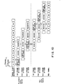
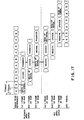
- FIG. 10 shows a dubbing timing in the case of carrying out a dubbing using the pair of identical apparatus of FIG. 5.
- a digital signal is first reproduced from a prerecorded tape 3 loaded thereto, and is written to the RAM 20 thereof at a rate of one frame being as a unit. Then, this digital signal is decoded by the decoder 15 at a rate of one frame being as a unit in a manner similar to the above, and is further transferred to the RAM 20 of the recording apparatus at the same frame rate.
- the digital data of the digital signal thus transferred are received at the same frame rate, and are then encoded by the encoder 14. Furthermore, the encoded digital data of one frame are recorded onto a blank tape 3 loaded into the recording apparatus.
- dubbing of one cycle is completed.
- RAMs corresponding to three frames of data are needed on each of the recording and playback apparatus, i.e. a total of 6 frames of RAMs (Of course, a single RAM with divided memory areas may be used).
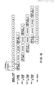
- the required RAM has a memory capacity corresponding to four frames, which is reduced by the memory capacity of two frames, as compared to the case shown in FIG. 10.
- a dubbing at the double speed may be conducted using the apparatus of FIG. 5.
- the running velocity of the tape 3 is represented by vector DE , the a magnitude of which is two times as much as that of the standard running velocity CE and is one half of that of the running velocity AB of the quadruple speed, wherein the direction of the velocity vector DE is the same as those of velocity vectors CE and AB
- the tangential velocities of the heads 6a to 6d are represented by vector O D and the drum rotational speed becomes equal to 2000 r.p.m. This rotational speed is equal to one in the standard mode of the conventional apparatus.
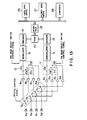
- FIG. 13 is a block diagram showing a third embodiment in which DAT is actually used as a data streamer wherein the same components as those in FIG. 5 are designated by the same reference numerals, respectively, and their explanation will be omitted.
- a hard disk drive (HDD) 26, a floppy disk drive (FDD) 27, and a DAT are connected to a computer 28 through an interface circuit 25.
- This arrangement is used for recording data stored in the HDD 26 and the FDD 27 onto a backup tape by means of the DAT. Because recording/playback at the double or the quadruple tape speeds can be conducted in this case, it is possible to transmit and receive data to and from the computer 28, etc. at a speed higher than that in the prior art.
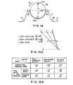
- FIG. 14 shows a rotary drum 29 and its peripheral arrangement according to a fourth embodiment of this invention.
- the diameter of the rotary drum 29 in the fourth embodiment is selected to 15.039 mm, which is substantially one half of 30 mm for the rotary drum 2 of the conventional apparatus shown in FIG. 1A, or 30.077 mm for the rotary drum 5 of the apparatus according to the first embodiment of this invention shown in FIG. 3.
- the tape 3 is wound onto the rotary drum 29 in an angular range of 180 degrees, and the lead angle in this case is set to 6 21'0.82"" in the same manner as in the case shown in FIG. 3.
- the recording and playback apparatus of the fourth embodiment is directed in its development to build a system which satisfactorily performs a dubbing at the double tape speed.
- the running velocity of the tape 3, the tangential velocity of the magnetic head 30a or 30b, and the relative velocity between the magnetic heads 30a and 30b and the tape 3 are shown as respective vector diagrams in FIGS. 15A and 15B.
- vector 6C represents a tangential velocity (2000 r.p.m. when the diameter of the rotary drum is 30 mm) of the magnetic head 30a or 30b in the standard mode of the conventional apparatus
- vector CE represents a running velocity (0.815 cm/sec) in the standard mode of the tape 3. Accordingly, a lead angle defined by the vectors OC and OP is equal to 6 22.
- FIG. 15B is a table collectively showing vectors in FIG. 15A corresponding to the tangential velocity of the magnetic head, the running velocity of the tape 3, and the relative velocity therebetween in the double speed mode and in the standard mode.
- the tangential velocity of the magnetic head 30a or 30b at that time is represented by vector OD .
- the relative velocity between the tape 3 and the magnetic head 30a or 30b is expressed as vector OE , which is in correspondence with the case in the standard mode of the conventional apparatus. Accordingly, in this case, the circuit characteristics of the magnetic heads 30a and 30b and the rotary transformer (not shown) in the rotary drum 29, etc. may be maintained same as ones for the conventional apparatus and the standard track angle 8 which is equal to an angle LEOP and the standard track length L are observed.
- the rotary drum 29 revolves at 2000 r.p.m.
- the tangential velocity of the magnetic head 30a or 30b is represented by vector OF of FIG. 15A and the relative velocity with respect to the tape 3 running at a velocity expressed as vector FG is represented by vector OG .
- This relative velocity is equal to one half of the relative velocity between the magnetic head and the tape 3 in the standard mode of the conventional apparatus and the standard track angle e which is equal to the angle LGOP and the standard track length L are observed.
- FIG. 16 is a block diagram of the recording and playback apparatus using rotary drum 29, etc. shown in FIG. 14.
- the same components as those in FIG. 11 are designated by the same reference numerals, respectively, and their explanation will be omitted.
- each frame is comprised of a set of A and B channels.
- PB playback
- respective operations of playback, decoding and transfer are carried out frame by frame and three frames by such complete one playback cycle.
- RAM having a memory capacity corresponding to three frames is required.
- a time period corresponding to one revolution of the rotary drum 29 is assumed as one cycle.
- a changeover switch 33 is connected to a playback side contact 33b.
- a changeover switch 32 is connected to a fixed contact 32a.
- the changeover switch 32 is connected to a fixed contact 32b. Since it takes 7.5 msec to reproduce one channel, the changeover switch 32 is switched to the contact 32a or 32b every 7.5 msec by the head select switch control signal.
- the reproduced signal is amplified by the playback amplifier 34, and is then demodulated by a demodulator circuit 35.
- the signal thus demodulated is written into a RAM 36.
- the signal data transferred from the RAM 36 is subjected to decoding and error correction performed by the decoder 37, and is then transferred through a terminal 37a as digital data to the other apparatus of the pair, which performs as a recorder.
- the changeover switch 33 is connected to a recording side contact 33a.
- the digital data having been transferred is through a terminal 38a first written into the RAM 36 of the recorder.
- a modulated digital data stored in the RAM 36 is encoded by an encoder 38, and is then modulated by a modulator 39.
- the digital signal of the A channel thus formed is written onto the tape 3 by means of the magnetic head 30a being amplified by the recording amplifier 40.
- a modulated digital signal of the B channel is written onto the tape 3 by means of the magnetic head 30b being amplified by the recording amplifier 40.
- recording is conducted while the changeover switch 32 is being switched by the head select switch control signal every 7.5 msec.
- the relative velocity between the magnetic head 30a or 30b and the tape 3 is the same as that in the standard mode, and the diameter of the rotary drum 29 is reduced to about one half of that of the conventional apparatus, resulting in the advantage that the entirety of the apparatus including mounting components for the drum can be small-sized and lightweight.
- the recording and playback apparatus of this embodiment constructed as stated has following advantages. Even in the case of carrying out recording/playback at the quadruple tape speed, by arranging such that the diameter of the rotary drum is equal to, e.g., 30.077 mm and the lead angle is equal to, e.g., 6 21'0.82", there may be adopted a rotational speed of the rotary drum equal to 4000 r.p.m. which is twice as much as that of the prior art. Accordingly, a stable operation of the running system is assured.
- the aforementioned double rotational speed of the drum may be realized only by allowing the rotary transformer and/or the magnetic head to have a frequency characteristic extended twice as wide as the conventional one, and by allowing the operating speeds for the demodulation of a reproduced signal and writing into the RAM in the playback system, and reading from the RAM and the modulation in the recording system to be twice as high as the conventional ones.
- the rotational speed of the rotary drum be equal to 2000 r.p.m.
- the relative velocity between the magnetic tape and the magnetic head becomes the standard relative velocity. Because the frequency characteristics and the operating speeds are the same as those in the conventional apparatus, conventional components may be used for the rotary transformer, the magnetic heads, the modulator/demodulator circuits and the like.
- the frequency characteristics of the magnetic head and the rotary transformer, the modulation/demodulation operating speeds, the operating speeds for writing/reading into and from the RAM, and the like may be maintained same as those in the conventional apparatus, and the diameter of the rotary drum may be about one half of the oen for the conventional apparatus, resulting in the advantage that the apparatus can be compact and lightweight.
Landscapes
- Engineering & Computer Science (AREA)
- Signal Processing (AREA)
- Multimedia (AREA)
- Digital Magnetic Recording (AREA)
- Signal Processing For Digital Recording And Reproducing (AREA)
- Recording Or Reproducing By Magnetic Means (AREA)
Applications Claiming Priority (2)
| Application Number | Priority Date | Filing Date | Title |
|---|---|---|---|
| JP8833640A JPH01208704A (ja) | 1988-02-16 | 1988-02-16 | デジタル信号記録再生装置 |
| JP33640/88 | 1988-02-16 |
Publications (3)
| Publication Number | Publication Date |
|---|---|
| EP0382959A2 true EP0382959A2 (de) | 1990-08-22 |
| EP0382959A3 EP0382959A3 (de) | 1991-05-15 |
| EP0382959B1 EP0382959B1 (de) | 1994-12-14 |
Family
ID=12392047
Family Applications (1)
| Application Number | Title | Priority Date | Filing Date |
|---|---|---|---|
| EP89301507A Expired - Lifetime EP0382959B1 (de) | 1988-02-16 | 1989-02-16 | Aufzeichnungs- und Wiedergabegerät für digitale Signale |
Country Status (4)
| Country | Link |
|---|---|
| US (1) | US5083225A (de) |
| EP (1) | EP0382959B1 (de) |
| JP (1) | JPH01208704A (de) |
| DE (1) | DE68920023T2 (de) |
Cited By (2)
| Publication number | Priority date | Publication date | Assignee | Title |
|---|---|---|---|---|
| EP0653746A3 (de) * | 1993-11-16 | 1996-02-28 | Daewoo Electronics Co Ltd | Mehrspuriges Schraubenabtastsystem. |
| EP0599919A4 (en) * | 1991-08-06 | 1996-10-16 | R Byte Inc | Digital data tape storage system. |
Families Citing this family (9)
| Publication number | Priority date | Publication date | Assignee | Title |
|---|---|---|---|---|
| DE69027643T2 (de) * | 1989-10-04 | 1996-12-19 | Mitsubishi Electric Corp | Magnetisches Aufzeichnungs- und Wiedergabegerät |
| US5247402A (en) * | 1989-11-14 | 1993-09-21 | Matsushita Electric Industrial Co., Ltd. | Apparatus for high speed searching and reproduction of data recorded in a tape medium |
| US5343337A (en) * | 1992-09-17 | 1994-08-30 | Digital Equipment Corporation | Control circuitry for magnetoresistive (MR) tape heads using group select switches and head select multiplexer |
| DE4303453A1 (de) * | 1993-02-08 | 1994-08-11 | Thomson Brandt Gmbh | Verfahren zum Aufzeichnen und Wiedergeben eines zeitkomprimierten Signals |
| US5699370A (en) * | 1994-02-17 | 1997-12-16 | Hitachi, Ltd. | Information recording and reproduction apparatus to be controlled by temporal information |
| US6681076B1 (en) | 1994-10-07 | 2004-01-20 | Victor Company Of Japan, Ltd. | Magnetic recording and reproducing apparatus for automatically setting the traveling speed of the recording medium in accordance with the transmission rate of the input digital signal |
| KR100202812B1 (ko) * | 1994-10-07 | 1999-06-15 | 슈즈이 다케오 | 자기기록 및 재생장치 |
| KR100203259B1 (ko) * | 1995-11-23 | 1999-06-15 | 윤종용 | 테이프 고속 복사를 위한 디지탈기록재생장치 |
| KR100188266B1 (ko) * | 1996-07-19 | 1999-06-01 | 윤종용 | 더블데크 브이시알에서의 고속복사장치 |
Family Cites Families (9)
| Publication number | Priority date | Publication date | Assignee | Title |
|---|---|---|---|---|
| JPS58101579A (ja) * | 1981-12-14 | 1983-06-16 | Sony Corp | 磁気記録装置 |
| CA1241739A (en) * | 1983-04-22 | 1988-09-06 | Takeshi Ninomiya | Magnetic recording and reproducing apparatus for recording and reproducing a video signal obtained from a high speed scanning video camera |
| US4628373A (en) * | 1983-06-10 | 1986-12-09 | Hitachi, Ltd. | Rotating head type magnetic record/reproduce apparatus |
| JPS61187103A (ja) * | 1985-02-14 | 1986-08-20 | Sony Corp | オ−デイオ信号の記録/再生装置 |
| CA1303729C (en) * | 1985-09-03 | 1992-06-16 | Tetsuro Kato | Method and apparatus for recording and/or reproducing a pcm signal |
| JPH0644375B2 (ja) * | 1986-07-22 | 1994-06-08 | 株式会社日立製作所 | デイジタル信号記録再生装置 |
| EP0254511B1 (de) * | 1986-07-22 | 1991-04-03 | Matsushita Electric Industrial Co., Ltd. | Gerät zur Wiedergabe von auf einem Band aufgenommenen Signalen |
| US4872070A (en) * | 1987-09-11 | 1989-10-03 | Electro Sound, Inc. | System and method for high speed video tape reproduction |
| US4888653A (en) * | 1987-12-28 | 1989-12-19 | Eastman Kodak Company | High speed video tape duplicator |
-
1988
- 1988-02-16 JP JP8833640A patent/JPH01208704A/ja active Pending
-
1989
- 1989-02-15 US US07/310,530 patent/US5083225A/en not_active Expired - Fee Related
- 1989-02-16 EP EP89301507A patent/EP0382959B1/de not_active Expired - Lifetime
- 1989-02-16 DE DE68920023T patent/DE68920023T2/de not_active Expired - Fee Related
Cited By (2)
| Publication number | Priority date | Publication date | Assignee | Title |
|---|---|---|---|---|
| EP0599919A4 (en) * | 1991-08-06 | 1996-10-16 | R Byte Inc | Digital data tape storage system. |
| EP0653746A3 (de) * | 1993-11-16 | 1996-02-28 | Daewoo Electronics Co Ltd | Mehrspuriges Schraubenabtastsystem. |
Also Published As
| Publication number | Publication date |
|---|---|
| EP0382959A3 (de) | 1991-05-15 |
| JPH01208704A (ja) | 1989-08-22 |
| DE68920023T2 (de) | 1995-04-20 |
| EP0382959B1 (de) | 1994-12-14 |
| US5083225A (en) | 1992-01-21 |
| DE68920023D1 (de) | 1995-01-26 |
Similar Documents
| Publication | Publication Date | Title |
|---|---|---|
| CA1322402C (en) | Magnetic recording and/or reproducing apparatus | |
| KR100245149B1 (ko) | 디지탈 신호 기록 재생 장치 | |
| US4594621A (en) | Rotary head type digital information signal recording and reproducing apparatus and tracking control method therein | |
| JPS62275302A (ja) | 磁気記録再生装置 | |
| US5083225A (en) | Digital signal recording and playback apparatus | |
| EP0085517B1 (de) | Anordnung zur Aufzeichnung von digitalen Signalen | |
| JPH0357527B2 (de) | ||
| EP0430043B1 (de) | Digitale Signalverarbeitungsschaltung | |
| US5742444A (en) | Recording and/or reproducing apparatus for controlling the running speed of a recording tape | |
| US4837641A (en) | Rotary head type digital signal recording and reproducing apparatus | |
| US5276557A (en) | Digital recording/reproducing apparatus | |
| US4875111A (en) | Apparatus for reproducing a digital signal | |
| US5170298A (en) | Record and reproduce signal processing circuit that is programmable according to the head drum configuration of the digital audio tape recorder in which it is used | |
| JPS6364604A (ja) | 回転ヘツド式デイジタル信号再生装置 | |
| EP0411998A2 (de) | 4-Kanal-PCM-Signalverarbeitungsgerät | |
| JP2505470B2 (ja) | 回転ヘッド形磁気記録再生装置 | |
| US5285326A (en) | Digital signal processor for converting between 4-channel PCM signals and 2-channel PCM signals | |
| JPH0542723B2 (de) | ||
| JPH0552589B2 (de) | ||
| US5581363A (en) | Method and apparatus for recording and reproducing video signal | |
| JP2718217B2 (ja) | 磁気記録再生装置 | |
| JP2752478B2 (ja) | 磁気記録再生装置 | |
| KR0166753B1 (ko) | 드럼 가변회전수에 대응하는 디지탈 영상기록재생장치 및 그 방법 | |
| JP3119053B2 (ja) | ディジタル信号記録再生装置 | |
| JPS60164902A (ja) | 回転ヘツド形磁気記録再生装置 |
Legal Events
| Date | Code | Title | Description |
|---|---|---|---|
| PUAI | Public reference made under article 153(3) epc to a published international application that has entered the european phase |
Free format text: ORIGINAL CODE: 0009012 |
|
| AK | Designated contracting states |
Kind code of ref document: A2 Designated state(s): DE FR GB |
|
| PUAL | Search report despatched |
Free format text: ORIGINAL CODE: 0009013 |
|
| AK | Designated contracting states |
Kind code of ref document: A3 Designated state(s): DE FR GB |
|
| 17P | Request for examination filed |
Effective date: 19910522 |
|
| 17Q | First examination report despatched |
Effective date: 19920911 |
|
| GRAA | (expected) grant |
Free format text: ORIGINAL CODE: 0009210 |
|
| AK | Designated contracting states |
Kind code of ref document: B1 Designated state(s): DE FR GB |
|
| REF | Corresponds to: |
Ref document number: 68920023 Country of ref document: DE Date of ref document: 19950126 |
|
| ET | Fr: translation filed | ||
| PLBE | No opposition filed within time limit |
Free format text: ORIGINAL CODE: 0009261 |
|
| STAA | Information on the status of an ep patent application or granted ep patent |
Free format text: STATUS: NO OPPOSITION FILED WITHIN TIME LIMIT |
|
| 26N | No opposition filed | ||
| PGFP | Annual fee paid to national office [announced via postgrant information from national office to epo] |
Ref country code: GB Payment date: 19970207 Year of fee payment: 9 |
|
| PGFP | Annual fee paid to national office [announced via postgrant information from national office to epo] |
Ref country code: FR Payment date: 19970211 Year of fee payment: 9 |
|
| PGFP | Annual fee paid to national office [announced via postgrant information from national office to epo] |
Ref country code: DE Payment date: 19970221 Year of fee payment: 9 |
|
| PG25 | Lapsed in a contracting state [announced via postgrant information from national office to epo] |
Ref country code: GB Free format text: LAPSE BECAUSE OF NON-PAYMENT OF DUE FEES Effective date: 19980216 |
|
| PG25 | Lapsed in a contracting state [announced via postgrant information from national office to epo] |
Ref country code: FR Free format text: THE PATENT HAS BEEN ANNULLED BY A DECISION OF A NATIONAL AUTHORITY Effective date: 19980228 |
|
| GBPC | Gb: european patent ceased through non-payment of renewal fee |
Effective date: 19980216 |
|
| PG25 | Lapsed in a contracting state [announced via postgrant information from national office to epo] |
Ref country code: DE Free format text: LAPSE BECAUSE OF NON-PAYMENT OF DUE FEES Effective date: 19981103 |
|
| REG | Reference to a national code |
Ref country code: FR Ref legal event code: ST |