EP0383202A2 - Stromdurchführung für Rezipienten mit heisser Wandung - Google Patents
Stromdurchführung für Rezipienten mit heisser Wandung Download PDFInfo
- Publication number
- EP0383202A2 EP0383202A2 EP90102542A EP90102542A EP0383202A2 EP 0383202 A2 EP0383202 A2 EP 0383202A2 EP 90102542 A EP90102542 A EP 90102542A EP 90102542 A EP90102542 A EP 90102542A EP 0383202 A2 EP0383202 A2 EP 0383202A2
- Authority
- EP
- European Patent Office
- Prior art keywords
- wall
- electrode
- sleeve
- sealing liquid
- recipient
- Prior art date
- Legal status (The legal status is an assumption and is not a legal conclusion. Google has not performed a legal analysis and makes no representation as to the accuracy of the status listed.)
- Granted
Links
Images

Classifications
-
- H—ELECTRICITY
- H01—ELECTRIC ELEMENTS
- H01B—CABLES; CONDUCTORS; INSULATORS; SELECTION OF MATERIALS FOR THEIR CONDUCTIVE, INSULATING OR DIELECTRIC PROPERTIES
- H01B17/00—Insulators or insulating bodies characterised by their form
- H01B17/26—Lead-in insulators; Lead-through insulators
- H01B17/30—Sealing
Definitions
- the invention relates to a current feedthrough for a recipient with a hot wall, a rod-shaped, vertically or quasi-vertically arranged electrode penetrating the wall.
- the current leadthrough according to the invention has an extremely low leakage rate when using a suitable sealing liquid, so that the microgaps between the components used for the current leadthrough do not have a negative effect either.
- liquid boron oxide B2O3 as a sealing liquid which, apart from being electrically insulating, is also largely chemically and thermally stable and has a low vapor pressure.
- B2O3 seals the micro-gaps due to its high viscosity without penetrating directly into these gaps.
- liquid hafnium fluoride (HfF4) or zirconium fluoride (ZrF4) can be used as a sealing liquid.
- the electrode protrudes not only from the top but also from the bottom of the sleeve and an upwardly open pot, which surrounds the lower end of the wall of the current leadthrough, is firmly connected to the electrode.
- the pot contains so much sealing liquid that the lower boundary of the wall is completely in the sealing liquid.
- the electrode, the bushing and the wall of the current feedthrough are dimensioned such that the lower end of the current feedthrough (ie the lower end of the bushing and wall) is in a temperature range are below 100 ° C.
- the lower end of the wall is sealed using a suitable seal (e.g. a commercially available power feedthrough) or a sealing material (e.g. an adhesive that is suitable for operating temperatures up to 100 ° C) gas-tight and electrically insulating connected to the electrode.
- FIG. 1 shows the current feedthrough for a recipient with a hot wall 1, the electrode 2 penetrating the wall 1.
- the electrode 2 is partially closely fitted in a cylindrical insulator sleeve 3 made of Al2O3.
- the sleeve 3 is closely fitted in a wall 4 which is tightly connected to the hot wall 1 of the recipient, the wall 4 above the sleeve 3 forming a space between itself and the electrode 2, which is partly filled with a suitable sealing liquid 5.
- a pot 6 is provided, which is open at the top and firmly connected to the electrode 2.
- the pot 6 also partially contains sealing liquid 5, to the extent that the lower end of the wall 4 is in the sealing liquid 5.
- the wall is over a flange 7 tightly connected to the wall 1 of the recipient.
- this current feedthrough works perfectly in the temperature range between 500 and 700 ° C. Even pressure differences between the upper and lower ends of the current feedthrough up to 2 bar resulted in leak rates that were below 10 ⁇ 7 mbar xl / sec.
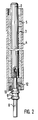
- FIG. 2 shows an exemplary embodiment in which the sealing of the current leadthrough, according to feature d of claim 4, is achieved by using a commercially available current leadthrough.
- the electrode 2 is closely fitted into the cylindrical insulator sleeve 3.
- the upper end of the electrode 2 forms, together with the wall 4 surrounding the sleeve 3, a space above the sleeve which is partially filled with sealing liquid 5.
- the commercially available feedthrough consists of an electrode 8, a wall 9 and an insulator ring 10.
- the electrode 8 is electrically connected to the electrode 2 by means of a thread.
- the wall 4 is soldered or welded to the wall 9 via the metallic connecting piece 12.
Landscapes
- Insulators (AREA)
- Connections Arranged To Contact A Plurality Of Conductors (AREA)
- Cookers (AREA)
- Installation Of Indoor Wiring (AREA)
- Piezo-Electric Or Mechanical Vibrators, Or Delay Or Filter Circuits (AREA)
- Sealing Battery Cases Or Jackets (AREA)
Abstract
Description
- Die Erfindung bezieht sich auf eine Stromdurchführung für einen Rezipienten mit heißer Wandung, wobei eine stabförmige, senkrecht oder quasi senkrecht angeordnete Elektrode die Wandung durchdringt.
- Die leckfreie Übertragung von elektrischen Strömen in einen Rezipienten mit heißer Wandung bei Temperaturen oberhalb 550°C ist, insbesondere bei korrosiver Atmosphäre, ein bisher nicht gelöstes, technisches Problem.
- Derartige Stromdurchführungen werden beispielsweise benötigt bei Kristallzucht-Apparaturen mit geschlossenem, beheiztem Rezipienten, bei denen unter anderem ein Tiegelheizer mit einem elektrischen Strom versorgt werden soll.
- Es ist Aufgabe der Erfindung, eine Stromdurchführung der eingangs bezeichneten Art zu schaffen, die eine leckfreie und elektrisch isolierte Übertragung des elektrischen Stroms in den Rezipienten auch dann möglich macht, wenn die Wandung des Rezipienten sich auf Temperaturen oberhalb 550°C befindet.
- Diese Aufgabe wird erfindungsgemäß durch eine Stromdurchführung mit den kennzeichnenden Merkmalen des Anspruchs 1 gelöst.
- Wie sich gezeigt hat, hat die erfindungsgemäße Stromdurchführung eine äußerst geringe Leckrate bei Verwendung einer geeigneten Dichtungsflüssigkeit, so daß sich auch die Mikrospalte zwischen den verwendeten Komponenten der Stromdurchführung nicht negativ auswirken.
- Als besonders vorteilhaft erweist sich der Einsatz von flüssigem Boroxid B₂O₃ als Dichtungsflüssigkeit, das außer elektrisch isolierend, zudem noch weitgehend chemisch und thermisch stabil ist und einen niedrigen Dampfdruck besitzt. Außerdem dichtet B₂O₃ aufgrund seiner hohen Viskosität die Mikrospalte gut ab, ohne direkt in diese Spalten einzudringen. Auch kann z. B. flüssiges Hafniumfluorid (HfF₄) oder Zirkonfluorid (ZrF₄) als Dichtungsflüssigkeit verwendet werden.
- In Ausbildung der Erfindung ist vorgesehen, daß die Elektrode nicht nur oben, sondern auch unten aus der Büchse herausragt und ein nach oben hin offener Topf, der das untere Ende der Wand der Stromdurchführung umgreift, fest mit der Elektrode verbunden ist. Der Topf enthält so viel Dichtungsflüssigkeit, daß sich die untere Begrenzung der Wand vollständig in der Dichtungsflüssigkeit befindet.
- Eine zweckmäßige Ausführung der Stromdurchführung ist gegeben durch die kennzeichnenden Merkmale des Anspruchs 4. Dabei sind die Elektrode, die Büchse und die Wand der Stromdurchführung so dimensioniert, daß das untere Ende der Stromdurchführung (also das untere Ende von Büchse und Wand) sich in einem Temperaturbereich unterhalb von 100°C befinden. Das untere Ende der Wand ist mittels einer geeigneten Abdichtung (z. B. eine handelsübliche Stromdurchführung) oder eines Dichtungsmaterials (z. B. ein Klebstoff der für Einsatztemperaturen bis 100°C geeignet ist) gasdicht und elektrisch isolierend mit der Elektrode verbunden.
- Die Stromdurchführung gemäß der Erfindung ist in den Zeichnungen 1 und 2 schematisch dargestellt und wird im folgenden näher erläutert.
- Es zeigen
- Figur 1 Stromdurchführung gemäß Anspruch 3, mit Topf zur Aufnahme von Dichtungsflüssigkeit;
- Figur 2 Stromdurchführung gemäß Anspruch 4, mit Abdichtung in Form einer handelsüblichen Stromdurchführung.
- In der Figur 1 ist die Stromdurchführung für einen Rezipienten mit heißer Wandung 1 dargestellt, wobei die Elektrode 2 die Wandung 1 durchdringt. Die Elektrode 2 ist teilweise eng in einer zylinderförmigen Isolatorbüchse 3 aus Al₂O₃ eingepaßt. Dabei ragt das obere, aus Graphit bestehende Ende der Elektrode aus der Büchse 3 heraus. Die Büchse 3 ist in einer mit der heißen Wandung 1 des Rezipienten dicht verbundenen Wand 4 eng eingepaßt, wobei die Wand 4 oberhalb der Büchse 3 zwischen sich und der Elektrode 2 einen Raum bildet, der zum Teil mit einer geeigneten Dichtungsflüssigkeit 5 gefüllt ist. Außerdem ist ein Topf 6 vorgesehen, der nach oben hin offen und fest mit der Elektrode 2 verbunden ist. Auch der Topf 6 enthält teilweise Dichtungsflüssigkeit 5 und zwar soviel, daß dabei das untere Ende der Wand 4 sich in der Dichtungsflüssigkeit 5 befindet. Die Wand ist über einen Flansch 7 mit der Wandung 1 des Rezipienten dicht verbunden. Diese Stromdurchführung zeigt bei Verwendung von Boroxid als Dichtungsflüssigkeit eine einwandfreie Funktion im Temperaturbereich zwischen 500 und 700°C. Sogar Druckdifferenzen zwischen dem oberen und dem unteren Ende der Stromdurchführung bis zu 2 bar ergaben Leckraten, die einen Wert unterhalb 10⁻⁷ mbar x l/sec hatten.
- In der Figur 2 ist ein Ausführungsbeispiel gezeigt, bei dem die Abdichtung der Stromdurchführung, gemäß dem Merkmal d des Anspruchs 4, durch den Einsatz einer handelsüblichen Stromdurchführung verwirklicht ist. In der schematisch verkürzten graphischen Darstellung der Stromdurchführung ist die Elektrode 2 eng in die zylinderförmige Isolatorbüchse 3 eingepaßt. Das obere Ende der Elektrode 2 bildet zusammen mit der die Büchse 3 umgebenden Wand 4 einen Raum oberhalb der Büchse, der mit Dichtungsflüssigkeit 5 teilweise gefüllt ist.
- Die handelsübliche Stromdurchführung besteht aus einer Elektrode 8, einer Wand 9 und einem Isolatorring 10. Dabei ist die Elektrode 8 mittels eines Gewindes elektrisch mit der Elektrode 2 verbunden. Über das metallische Verbindungsstück 12 ist die Wand 4 mit der Wand 9 verlötet bzw. verschweißt.
Claims (4)
dadurch gekennzeichnet,
dab
dadurch gekennzeichnet,
daß als Dichtungsflüssigkeit (5) Boroxid vorgesehen ist.
dadurch gekennzeichnet,
daß die Elektrode (2) auch nach unten aus der Büchse (3) herausragt und ein nach oben hin offener, fest mit der Elektrode verbundener Topf (6) zur Aufnahme von Dichtungsflüssigkeit (5) vorgesehen ist, der das untere Ende der Wand (4) umgreift.
daß
Applications Claiming Priority (2)
| Application Number | Priority Date | Filing Date | Title |
|---|---|---|---|
| DE3904195 | 1989-02-13 | ||
| DE3904195A DE3904195A1 (de) | 1989-02-13 | 1989-02-13 | Stromdurchfuehrung fuer rezipienten mit heisser wandung |
Publications (3)
| Publication Number | Publication Date |
|---|---|
| EP0383202A2 true EP0383202A2 (de) | 1990-08-22 |
| EP0383202A3 EP0383202A3 (en) | 1990-11-14 |
| EP0383202B1 EP0383202B1 (de) | 1994-07-20 |
Family
ID=6373933
Family Applications (1)
| Application Number | Title | Priority Date | Filing Date |
|---|---|---|---|
| EP90102542A Expired - Lifetime EP0383202B1 (de) | 1989-02-13 | 1990-02-09 | Stromdurchführung für Rezipienten mit heisser Wandung |
Country Status (4)
| Country | Link |
|---|---|
| US (1) | US5068492A (de) |
| EP (1) | EP0383202B1 (de) |
| JP (1) | JPH02246718A (de) |
| DE (2) | DE3904195A1 (de) |
Families Citing this family (2)
| Publication number | Priority date | Publication date | Assignee | Title |
|---|---|---|---|---|
| JP2002270125A (ja) * | 2001-03-07 | 2002-09-20 | Hitachi Ltd | 高電圧電気機器 |
| EP2984657B1 (de) * | 2013-04-10 | 2021-05-26 | Sentech AS | Hochspannungsstromdurchführungsvorrichtung |
Family Cites Families (7)
| Publication number | Priority date | Publication date | Assignee | Title |
|---|---|---|---|---|
| GB206510A (en) * | 1922-11-03 | 1924-05-29 | Bbc Brown Boveri & Cie | Improvements in vacuum-tight sleeve-insulators for leading electrodes through the walls of metal vessels |
| GB520207A (en) * | 1938-10-21 | 1940-04-17 | Siemens Lurgi Cottrell Elektro | Improvements in or relating to leading-in insulators for high tension current |
| US2942615A (en) * | 1957-11-25 | 1960-06-28 | Cons Vacuum Corp | Liquid seals |
| DE1640012A1 (de) * | 1968-03-12 | 1970-07-09 | Steinzeug Und Kunststoffwarenf | Elektrische Stromdurchfuehrung |
| DE2133190A1 (de) * | 1971-07-03 | 1973-01-11 | Sachsenwerk Licht & Kraft Ag | Hochspannungs-leistungsschalter |
| DE7512782U (de) * | 1975-04-22 | 1975-09-04 | Kellner E | Elektrische Vakuum-Durchführung |
| US4512791A (en) * | 1981-11-16 | 1985-04-23 | Kyle James C | Hermetically sealed insulating assembly |
-
1989
- 1989-02-13 DE DE3904195A patent/DE3904195A1/de active Granted
-
1990
- 1990-02-09 EP EP90102542A patent/EP0383202B1/de not_active Expired - Lifetime
- 1990-02-09 DE DE59006460T patent/DE59006460D1/de not_active Expired - Fee Related
- 1990-02-09 JP JP2028638A patent/JPH02246718A/ja active Pending
- 1990-02-12 US US07/479,085 patent/US5068492A/en not_active Expired - Fee Related
Also Published As
| Publication number | Publication date |
|---|---|
| EP0383202A3 (en) | 1990-11-14 |
| US5068492A (en) | 1991-11-26 |
| EP0383202B1 (de) | 1994-07-20 |
| DE3904195A1 (de) | 1990-08-23 |
| JPH02246718A (ja) | 1990-10-02 |
| DE59006460D1 (de) | 1994-08-25 |
| DE3904195C2 (de) | 1991-03-28 |
Similar Documents
| Publication | Publication Date | Title |
|---|---|---|
| DE2819407C3 (de) | Dichtungsmasse für Keramiken sowie Entladungsgerät unter Verwendung dieser Dichtungsmasse | |
| EP2977690B1 (de) | Verfahren zum vakuumdichten Verschließen eines doppelwandigen Glasrohrs | |
| DE2641880C2 (de) | ||
| DE1571502A1 (de) | Verfahren zum Verschliessen einer Roehre aus feuerfestem Oxid-Material | |
| EP0383202B1 (de) | Stromdurchführung für Rezipienten mit heisser Wandung | |
| DE2207009A1 (de) | Ueberspannungsableiter | |
| DE1233828B (de) | Verfahren zur Herstellung, Reinigung und/oder Dotierung von ein- oder polykristallinen Halbleiterverbindungen | |
| DE69918802T2 (de) | Elektrische lampe | |
| DE1916318B2 (de) | Stromdurchführung für eine Vorrichtung zum Zonenschmelzen | |
| DE2828412C2 (de) | Durchführung einer Leitung durch einen Wandteil eines Behälters | |
| DE1519837B2 (de) | Verfahren zum zonenschmelzen oder kristallziehen | |
| DE1933130C3 (de) | Stromdurchführung für einen Kolben einer mit hoher Stromstärke betriebenen elektrischen Einrichtung, insbesondere einer elektrischen Lampe | |
| DE7212987U (de) | Elektrische lampe u.dgl. | |
| DE2425025A1 (de) | Elektrode fuer einen glasschmelzofen | |
| DE596392C (de) | Endverschluss fuer Einleiterbleikabel | |
| DE3012322A1 (de) | Gegenstand mit einer dichtungsmasse mit kalziumoxid, bariumoxid und aluminiumoxid | |
| DE4014246C2 (de) | ||
| CH246358A (de) | Elektrische Vorrichtung mit einem unter innerem Überdruck stehenden Behälter, in welchem Hochspannung führende Teile der Vorrichtung untergebracht sind, und Verfahren zu deren Herstellung. | |
| DE329421C (de) | Vorrichtung zur Regelung des Haertegrades von Roentgenroehren | |
| DE967110C (de) | Kondensatorkoerper fuer Muffen und Endverschluesse elektrischer Kabel sowie fuer Durchfuehrungen fuer Hochspannungsgeraete | |
| DE1208006B (de) | Transistor in einer metallischen Kapsel | |
| AT155281B (de) | Gasdichtes elektrisches Gefäß. | |
| DE1117683B (de) | Gasdichte, durch ein umlaufendes Kuehlmittel gekuehlte Durchfuehrung mit rohrfoermigem Isolierkoerper fuer hohe Stromstaerken | |
| DE944026C (de) | Elektrodentieffassung | |
| DE643397C (de) | Verfahren zur Herstellung von Tiefbohrungen |
Legal Events
| Date | Code | Title | Description |
|---|---|---|---|
| PUAI | Public reference made under article 153(3) epc to a published international application that has entered the european phase |
Free format text: ORIGINAL CODE: 0009012 |
|
| AK | Designated contracting states |
Kind code of ref document: A2 Designated state(s): CH DE FR GB LI SE |
|
| PUAL | Search report despatched |
Free format text: ORIGINAL CODE: 0009013 |
|
| AK | Designated contracting states |
Kind code of ref document: A3 Designated state(s): CH DE FR GB LI SE |
|
| 17P | Request for examination filed |
Effective date: 19901205 |
|
| 17Q | First examination report despatched |
Effective date: 19921015 |
|
| GRAA | (expected) grant |
Free format text: ORIGINAL CODE: 0009210 |
|
| AK | Designated contracting states |
Kind code of ref document: B1 Designated state(s): CH DE FR GB LI SE |
|
| REF | Corresponds to: |
Ref document number: 59006460 Country of ref document: DE Date of ref document: 19940825 |
|
| GBT | Gb: translation of ep patent filed (gb section 77(6)(a)/1977) |
Effective date: 19940815 |
|
| RIN2 | Information on inventor provided after grant (corrected) |
Free format text: BRITZ, LOTHAR * KRUG, WOLFGANG * SEFERIADIS, JOHANN |
|
| ET | Fr: translation filed | ||
| EAL | Se: european patent in force in sweden |
Ref document number: 90102542.9 |
|
| PLBE | No opposition filed within time limit |
Free format text: ORIGINAL CODE: 0009261 |
|
| STAA | Information on the status of an ep patent application or granted ep patent |
Free format text: STATUS: NO OPPOSITION FILED WITHIN TIME LIMIT |
|
| 26N | No opposition filed | ||
| PGFP | Annual fee paid to national office [announced via postgrant information from national office to epo] |
Ref country code: GB Payment date: 19980202 Year of fee payment: 9 |
|
| PGFP | Annual fee paid to national office [announced via postgrant information from national office to epo] |
Ref country code: FR Payment date: 19980216 Year of fee payment: 9 |
|
| PGFP | Annual fee paid to national office [announced via postgrant information from national office to epo] |
Ref country code: SE Payment date: 19980219 Year of fee payment: 9 |
|
| PGFP | Annual fee paid to national office [announced via postgrant information from national office to epo] |
Ref country code: CH Payment date: 19980220 Year of fee payment: 9 |
|
| PG25 | Lapsed in a contracting state [announced via postgrant information from national office to epo] |
Ref country code: GB Free format text: LAPSE BECAUSE OF NON-PAYMENT OF DUE FEES Effective date: 19990209 |
|
| PG25 | Lapsed in a contracting state [announced via postgrant information from national office to epo] |
Ref country code: SE Free format text: LAPSE BECAUSE OF NON-PAYMENT OF DUE FEES Effective date: 19990210 |
|
| PG25 | Lapsed in a contracting state [announced via postgrant information from national office to epo] |
Ref country code: LI Free format text: LAPSE BECAUSE OF NON-PAYMENT OF DUE FEES Effective date: 19990228 Ref country code: CH Free format text: LAPSE BECAUSE OF NON-PAYMENT OF DUE FEES Effective date: 19990228 |
|
| GBPC | Gb: european patent ceased through non-payment of renewal fee |
Effective date: 19990209 |
|
| REG | Reference to a national code |
Ref country code: CH Ref legal event code: PL |
|
| PG25 | Lapsed in a contracting state [announced via postgrant information from national office to epo] |
Ref country code: FR Free format text: LAPSE BECAUSE OF NON-PAYMENT OF DUE FEES Effective date: 19991029 |
|
| EUG | Se: european patent has lapsed |
Ref document number: 90102542.9 |
|
| REG | Reference to a national code |
Ref country code: FR Ref legal event code: ST |
|
| PGFP | Annual fee paid to national office [announced via postgrant information from national office to epo] |
Ref country code: DE Payment date: 19991224 Year of fee payment: 11 |
|
| PG25 | Lapsed in a contracting state [announced via postgrant information from national office to epo] |
Ref country code: DE Free format text: LAPSE BECAUSE OF NON-PAYMENT OF DUE FEES Effective date: 20011201 |