EP0383207A1 - Curseur de fermeture à glissière, muni d'un système de blocage automatique - Google Patents
Curseur de fermeture à glissière, muni d'un système de blocage automatique Download PDFInfo
- Publication number
- EP0383207A1 EP0383207A1 EP90102564A EP90102564A EP0383207A1 EP 0383207 A1 EP0383207 A1 EP 0383207A1 EP 90102564 A EP90102564 A EP 90102564A EP 90102564 A EP90102564 A EP 90102564A EP 0383207 A1 EP0383207 A1 EP 0383207A1
- Authority
- EP
- European Patent Office
- Prior art keywords
- locking
- slider
- locking member
- lugs
- slide fasteners
- Prior art date
- Legal status (The legal status is an assumption and is not a legal conclusion. Google has not performed a legal analysis and makes no representation as to the accuracy of the status listed.)
- Granted
Links
Images


Classifications
-
- A—HUMAN NECESSITIES
- A44—HABERDASHERY; JEWELLERY
- A44B—BUTTONS, PINS, BUCKLES, SLIDE FASTENERS, OR THE LIKE
- A44B19/00—Slide fasteners
- A44B19/24—Details
- A44B19/26—Sliders
- A44B19/262—Pull members; Ornamental attachments for sliders
-
- A—HUMAN NECESSITIES
- A44—HABERDASHERY; JEWELLERY
- A44B—BUTTONS, PINS, BUCKLES, SLIDE FASTENERS, OR THE LIKE
- A44B19/00—Slide fasteners
- A44B19/24—Details
- A44B19/26—Sliders
-
- A—HUMAN NECESSITIES
- A44—HABERDASHERY; JEWELLERY
- A44B—BUTTONS, PINS, BUCKLES, SLIDE FASTENERS, OR THE LIKE
- A44B19/00—Slide fasteners
- A44B19/24—Details
- A44B19/26—Sliders
- A44B19/30—Sliders with means for locking in position
-
- A—HUMAN NECESSITIES
- A44—HABERDASHERY; JEWELLERY
- A44B—BUTTONS, PINS, BUCKLES, SLIDE FASTENERS, OR THE LIKE
- A44B19/00—Slide fasteners
- A44B19/24—Details
- A44B19/26—Sliders
- A44B19/30—Sliders with means for locking in position
- A44B19/308—Sliders with means for locking in position in the form of a spring-actuated locking member actuated by the pull member
-
- Y—GENERAL TAGGING OF NEW TECHNOLOGICAL DEVELOPMENTS; GENERAL TAGGING OF CROSS-SECTIONAL TECHNOLOGIES SPANNING OVER SEVERAL SECTIONS OF THE IPC; TECHNICAL SUBJECTS COVERED BY FORMER USPC CROSS-REFERENCE ART COLLECTIONS [XRACs] AND DIGESTS
- Y10—TECHNICAL SUBJECTS COVERED BY FORMER USPC
- Y10T—TECHNICAL SUBJECTS COVERED BY FORMER US CLASSIFICATION
- Y10T24/00—Buckles, buttons, clasps, etc.
- Y10T24/25—Zipper or required component thereof
- Y10T24/2561—Slider having specific configuration, construction, adaptation, or material
- Y10T24/2566—Slider having specific configuration, construction, adaptation, or material including position locking-means attached thereto
- Y10T24/2568—Protrusion on pull tab directly engaging interlocking surfaces
-
- Y—GENERAL TAGGING OF NEW TECHNOLOGICAL DEVELOPMENTS; GENERAL TAGGING OF CROSS-SECTIONAL TECHNOLOGIES SPANNING OVER SEVERAL SECTIONS OF THE IPC; TECHNICAL SUBJECTS COVERED BY FORMER USPC CROSS-REFERENCE ART COLLECTIONS [XRACs] AND DIGESTS
- Y10—TECHNICAL SUBJECTS COVERED BY FORMER USPC
- Y10T—TECHNICAL SUBJECTS COVERED BY FORMER US CLASSIFICATION
- Y10T24/00—Buckles, buttons, clasps, etc.
- Y10T24/25—Zipper or required component thereof
- Y10T24/2561—Slider having specific configuration, construction, adaptation, or material
- Y10T24/2566—Slider having specific configuration, construction, adaptation, or material including position locking-means attached thereto
- Y10T24/257—Slider having specific configuration, construction, adaptation, or material including position locking-means attached thereto having surface engaging element shifted by reorientation of pull tab
-
- Y—GENERAL TAGGING OF NEW TECHNOLOGICAL DEVELOPMENTS; GENERAL TAGGING OF CROSS-SECTIONAL TECHNOLOGIES SPANNING OVER SEVERAL SECTIONS OF THE IPC; TECHNICAL SUBJECTS COVERED BY FORMER USPC CROSS-REFERENCE ART COLLECTIONS [XRACs] AND DIGESTS
- Y10—TECHNICAL SUBJECTS COVERED BY FORMER USPC
- Y10T—TECHNICAL SUBJECTS COVERED BY FORMER US CLASSIFICATION
- Y10T24/00—Buckles, buttons, clasps, etc.
- Y10T24/25—Zipper or required component thereof
- Y10T24/2561—Slider having specific configuration, construction, adaptation, or material
- Y10T24/2566—Slider having specific configuration, construction, adaptation, or material including position locking-means attached thereto
- Y10T24/257—Slider having specific configuration, construction, adaptation, or material including position locking-means attached thereto having surface engaging element shifted by reorientation of pull tab
- Y10T24/2571—Resilient or spring biased element
- Y10T24/2577—Biased by distinct spring
Definitions
- the present invention generally relates to an automatic locking slider for slide fasteners and in particular to an automatic locking slider of the type having a locking member pivotally supported by and between a pair of opposed lugs provided on the upper surface of the slider.
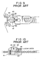
- the conventional automatic locking slider comprises a slider body 121 including a pair of upper and lower wings 122, 122′ joined together at their front ends, the upper wing 122 having a pair of opposed thinned lugs 123, 123 protuberantly provided substantially centrally on its upper surface.
- a thinned locking member 125 is partly disposed between the opposed lugs 123, 123 and pivottaly mounted on a pivotal pin 124 secured between the opposed lugs 123, 123. The locking member 125 projects exposed forwardly beyond the front edges of the lugs 123, 123.
- the conventional automatic locking slider has several disadvantages.
- the locking member 125 is hardly protected by the lugs 123, 123, in other words, the locking member 125 is exposed widely at its front and rear portions, so that it is very vulnerable or liable to stresses applied by other things. Consequently, the locking prong of the locking member 125 would be apt to come out of locking engagement with fastener elements accidentally, so that the conventional automatic locking slider suffers from unreliability in automatic locking function.
- the lugs 123, 123 and the locking members 125 are liable to deformation or damage. Since the mechanical strength of such parts is generally proportioned to the size of a slider as a whole, such deformation or damage is more likely to occur in a small slider.
- the lugs 123, 123 and the locking member 125 disposed therebetween are both less in thickness and project considerably high for the area on the upper surface of the upper wing 122 which they occupy, so that they are inclined to irritate the skin of the wearer or otherwise impart objectionable uncomfortable feeling to him.
- an automatic locking slider for slide fasteners comprising a slider body including a pair of upper and lower wings joined together, the upper wing having a pair of opposed lugs provided protuberantly on its upper surface adjacent its front end to thus define a groove therebetween; a locking member fitted in the groove and pivotted at its middle to the opposed lugs, the locking member having at its rear end a locking prong; a spring member provided on the slider body for normally urging the front end of the locking member upwardly so as to bring the locking prong into locking disposition; and a pull tab for pulling up the rear end of the locking member so as to bring the locking prong out of locking disposition for reciprocation of the slider; the lugs being so bulged roundedly as to have their respective outer sides to extend substantially to and merge into the edge of the front end and as to substantially enclose a front half of the locking member on its opposed sides.
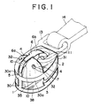
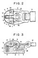
- FIGS. 1 through 3 show an automatic locking slider for slide fasteners embodying the present invention.
- the automatic locking slider broadly comprises a slider body 1, a pull tab support 13 pivotally joined to the slider body 1 and a pull tab 14 pivotally joined to the pull tab support 13.
- the slider body 1 includes a pair of upper and lower wings 2, 3 and has a front end 30 and a converged rear end 31.
- the upper and lower wings 2, 3 are joined to each other at the front end 30 by a neck portion 35 to thus define therebetween a Y-shaped channel 38 for passage of fastener element rows of slide fastener stringers to open and close the slide fastener.
- a pair of lugs 4, 4 are protuberantly mounted on the upper surface adjacent the front end 30 of the upper wing 2 and disposed in opposed relation to each other to thus define a groove 5 between the respective confronting inner sides of the lugs 4, 4.
- Each of the lugs 4, 4 is so bulged roundedly on its outer side as to have the convex outer side substantially extend to and merge into the edge 30a of the front end 30, as best shown in FIG. 1.
- a locking member 6 is fitted at its front half 6a in the groove 5. As better shown in FIGS.
- the front half 6a of the locking member 6 is substantially enclosed on its opposed sides by the bulged lugs 4, 4, so that the former is sufficiently protected by the latter against deformation or damages even under severe stresses exerted on the front half 6a of the locking member 6.
- the locking member 6 is pivoted at its a middle to a pivotal pin 7 supported between the opposed lugs 4, 4 so as to rotate on the pivotal pin 7.
- the pivotal pin 7 is inserted through a pair of aligned through holes 32, 32 formed in the lugs adjacent their rear ends.
- the pivotal pin 7 is secured to the lugs 4, 4 against detachment from the through holes 32, 32 by swaging overhanging slant edges of the holes 32, 32 to the ends of the pivotal pin 7. As best seen in FIG.
- the swaging can be effected very yieldingly or easily and the thus swaged portions are not so conspicuous.
- the rear half 6b of the locking member 6 which extends exposed out of between the lugs 4, 4 is formed greater in width than the front half 6a lying within between the lugs 4, 4. This advantageously helps to reinforce the rear half 6b of the locking member 6 left unprotected and hence the locking member 6 as a whole, thereby conducing to stabilization of the automatic locking function of the slider.
- the locking member 6 is formed on its upper side so arcuate as to confirm with the convexities of the bulged lugs 4, 4, to thus help the upper surface of the upper wing 2 as a whole look and feel rounded and mild.
- a cylindrical blind bore 8 is formed in the neck portion 35 and communicates at its upper end with the groove 5.
- a compression coil spring 9 is fitted in the blind bore 8 and normally urges the front end of the locking member 6 upwardly so as to rotate the locking member 6 clockwise, as viewed in FIG. 3.
- a pair of concave recesses 10, 10 are formed in the opposed inner surfaces of the lugs 4, 4 in confronting relation to each other, the concave recesses 10, 10 merging into the relevent confronting parts of the inner periphery of the blind bore 8, for facilitating insertion of the compression coil spring 9 into the blind bore 8 during assemblage of the automatic locking slider.
- the upper wing 2 has adjacent to the converged rear end 31 a through opening 11 communicating with the Y-shaped channel 38.
- the rear half 6b of the locking member 6 is bent arcuately and terminates in a locking prong 12.
- the locking member 6 is rotated clockwise, as viewed in FIG. 3, under the bias of the compression coil spring 9 fitted in the blind bore 8, so that the locking prong 12 passes through the opening 11 into the Y-shaped channel 38 for locking engagement with the fastener elements of the slide fastener stringers within the Y-shaped channel 12, thus bringing the slider in locked disposition.
- a pull tab 14 is pulled upwardly to thus rotate the locking member 6 anti-clockwise (as viewed in FIG. 3), thereby bringing the locking prong 12 out of locking engagement with the fastener elements, so that the slider can now reciprocate on and along the fastener element rows smoothly for opening and closing the slide fastener.
- the pull tab 14 is joined to the locking member 6 via the pull tab support 13 so that the pull tab 14 is yieldingly and freely movable in various directions under stresses exerted thereon. This means that the pull tab 14 will not resist to the skin of the wearer, thus imparting the wearer soft and comfortable touch.
- FIG. 5 shows another embodiment of the present invention wherein a pull tab 14 is made of flexible materials such as flexible synthetic resin or flexible synthetic rubber and has a connecting ring 37 planted into its one end for direct connection with the locking member 6.
- a pull tab 14 is made of flexible materials such as flexible synthetic resin or flexible synthetic rubber and has a connecting ring 37 planted into its one end for direct connection with the locking member 6.
- Such use of flexible materials for the pull tab 14 further would help to make the slider as a whole feel more soft and mild. .
- FIG. 6 shows still another embodiment of the present invention wherein the rear half 6b of the locking member 6 extending beyond between the lugs 4, 4, although having substantially the same width of the front half 6a lying within the groove 5, is slightly offset relative to the front half 6a, so as to ensure that the locking prong 12 comes into interlocking engagement with between adjacent fastener elements of the slide fastener stringers.
- FIG. 7 shows yet another embodiment wherein, instead of the cylindrical blind bore 8, a concave recess 8a is formed in the upper surface of the upper wing 2 adjacent the front end 30 and, instead of the compression coil spring 9, a flat plate spring 9a is laid over the concave recess 8a.
- the locking member 6 is provided on the lower surface of the front end with an abutment projection 6c.
- the plate spring 9a acts on the projection 6a so as to urge the front end of the locking member 6 upwardly to thus rotate the locking member 6 clockwise as viewed in FIG. 7.
- FIG. 8 shows still another embodiment wherein the upper wing 2 has a furrow 8b in its upper surface adjacent to the front end 30, whose bottom slants downwardly toward the front end 30.
- a tortional helical spring 9b is laid in the slant-bottomed furrow 8b and is secured at its one end to the bottom of the furrow 8b and at the other end to the lower surface of the front end of the locking member 6 so as to urge the front end of the locking member 6 upwardly to thus rotate the locking member 6 clockwise as viewed in FIG. 8.
- the opposed lugs 4, 4 are so bulged roundedly as to substantially enclose the front half 6a of the locking member 6 on its opposed sides which front half would be otherwise liable to deformation or damage, the locking member 6 is less subjected to stresses exerted on the slider, thereby enjoying reliable locking function for a prolonged period of time.
- the lugs 4, 4 are so bulged roundedly as to extend substantially to and merge into the edge 30a of the front end 30 of the upper wing 2, thereby help to make the slider as a whole look attractive and mild and touches soft and comfortable. Therefore, the construction of the present invention is advantageous particularly in being applied to a small slider in which a locking member 6 occupys a larger space relatively to the whole size of the slider.
Landscapes
- Slide Fasteners (AREA)
Applications Claiming Priority (2)
| Application Number | Priority Date | Filing Date | Title |
|---|---|---|---|
| JP33487/89 | 1989-02-13 | ||
| JP1033487A JPH02213302A (ja) | 1989-02-13 | 1989-02-13 | スライドファスナー用自動停止装置付スライダー |
Publications (2)
| Publication Number | Publication Date |
|---|---|
| EP0383207A1 true EP0383207A1 (fr) | 1990-08-22 |
| EP0383207B1 EP0383207B1 (fr) | 1995-01-25 |
Family
ID=12387913
Family Applications (1)
| Application Number | Title | Priority Date | Filing Date |
|---|---|---|---|
| EP90102564A Expired - Lifetime EP0383207B1 (fr) | 1989-02-13 | 1990-02-09 | Curseur de fermeture à glissière, muni d'un système de blocage automatique |
Country Status (10)
| Country | Link |
|---|---|
| US (1) | US4982479A (fr) |
| EP (1) | EP0383207B1 (fr) |
| JP (1) | JPH02213302A (fr) |
| KR (1) | KR920001864B1 (fr) |
| AU (1) | AU621982B2 (fr) |
| BR (1) | BR9000708A (fr) |
| CA (1) | CA2009174C (fr) |
| DE (1) | DE69016219T2 (fr) |
| ES (1) | ES2067575T3 (fr) |
| MY (1) | MY105524A (fr) |
Cited By (3)
| Publication number | Priority date | Publication date | Assignee | Title |
|---|---|---|---|---|
| EP0943254A3 (fr) * | 1998-03-16 | 1999-12-08 | Ykk Corporation | Curseur de fermeture à glissière comprenant un mécanisme de verrouillage automatique |
| CN102920113A (zh) * | 2012-11-04 | 2013-02-13 | 李甫文 | 隐形拉链头 |
| US8966720B2 (en) | 2009-12-25 | 2015-03-03 | Ykk Corporation | Slider for slide fastener |
Families Citing this family (17)
| Publication number | Priority date | Publication date | Assignee | Title |
|---|---|---|---|---|
| US5255418A (en) * | 1992-11-10 | 1993-10-26 | Chen Shih Chung | Automatically locking slider for concealed zipper |
| US5551129A (en) * | 1995-12-07 | 1996-09-03 | Chu; Tino | Slider of a zipper |
| JP3580337B2 (ja) * | 1997-02-28 | 2004-10-20 | Ykk株式会社 | 隠しスライドファスナー用スライダー |
| JP3589438B2 (ja) * | 1997-05-16 | 2004-11-17 | Ykk株式会社 | スライドファスナー用スライダー |
| JP3599617B2 (ja) * | 1999-10-29 | 2004-12-08 | Ykk株式会社 | スライドファスナー用スライダーの引手 |
| CN100553514C (zh) * | 2004-11-16 | 2009-10-28 | 瑞伊有限公司 | 具有可换拉片的拉链的拉头 |
| US8122573B2 (en) * | 2009-01-07 | 2012-02-28 | Ykk Corporation | Thin slider |
| EP2391236B1 (fr) * | 2009-01-30 | 2015-03-11 | Columbia Sportswear North America, Inc. | Dispositif de fermeture coulissant anti-accrochage |
| US8453301B1 (en) * | 2010-07-22 | 2013-06-04 | Patty McCoy | Zipper pull tab retention device |
| EP2620072B1 (fr) * | 2010-09-24 | 2017-07-12 | YKK Corporation | Curseur pour fermetures à glissière pourvu d'un dispositif d'arrêt automatique |
| US20140123445A1 (en) * | 2011-06-21 | 2014-05-08 | Ji Ong Jung | Automatic locking slider for slide fastener |
| WO2013001597A1 (fr) * | 2011-06-28 | 2013-01-03 | Ykk株式会社 | Curseur pour fermetures à glissière |
| GB2514215A (en) * | 2013-03-01 | 2014-11-19 | Coats Ltd J & P | Zip fastener |
| US11678728B2 (en) * | 2016-11-23 | 2023-06-20 | Zhejiang Weixing Industrial Development Co., Ltd. | Zipper and garment having the same |
| CN207561458U (zh) * | 2017-06-16 | 2018-07-03 | Ykk株式会社 | 拉链用拉头 |
| TWI662914B (zh) * | 2018-05-09 | 2019-06-21 | 大陸商濰坊中傳拉鏈配件有限公司 | 拉鍊頭組合結構及其連接套環 |
| TWI661789B (zh) * | 2018-06-27 | 2019-06-11 | 大陸商濰坊中傳拉鏈配件有限公司 | 鎖鉤件及拉鍊頭組合結構 |
Citations (9)
| Publication number | Priority date | Publication date | Assignee | Title |
|---|---|---|---|---|
| DE648831C (de) * | 1937-08-11 | Ernst Piezug | Feststellbarer Reissverschlussschieber | |
| US2450550A (en) * | 1945-07-26 | 1948-10-05 | Us Rubber Co | Locking slider for slide fasteners |
| GB661719A (en) * | 1949-05-31 | 1951-11-28 | Flex Fasteners Ltd | Improvements in or relating to sliders for sliding clasp fasteners |
| US2882576A (en) * | 1953-01-22 | 1959-04-21 | Louis H Morin | Slider for separable fasteners |
| FR1194766A (fr) * | 1957-04-18 | 1959-11-12 | Lightning Fasteners Ltd | Perfectionnements aux curseurs pour fermetures |
| GB1066874A (en) * | 1964-06-15 | 1967-04-26 | Lightning Fasteners Ltd | Improvements in or relating to sliders for sliding clasp fasteners |
| DE1610438A1 (de) * | 1966-10-26 | 1971-04-15 | Dittmayer Kg K | Schieber fuer Reissverschluesse mit Kunststoff-Gliederreihen |
| FR2242049A1 (fr) * | 1973-09-05 | 1975-03-28 | Fermeture Ailee Sa | |
| JPS62102407U (fr) * | 1985-12-20 | 1987-06-30 |
Family Cites Families (9)
| Publication number | Priority date | Publication date | Assignee | Title |
|---|---|---|---|---|
| FR1049534A (fr) * | 1951-10-29 | 1953-12-30 | Manufactures Francaises De Bou | Perfectionnements aux curseurs de fermetures à glissieres à blocage automatique |
| US2900695A (en) * | 1953-03-05 | 1959-08-25 | Louis H Morin | Automatic lock sliders |
| US2867881A (en) * | 1955-03-16 | 1959-01-13 | Louis H Morin | Jam-freeing slider for separable fasteners |
| US3284864A (en) * | 1965-04-26 | 1966-11-15 | Robert B Howell | Slider |
| DE1274842B (de) * | 1966-03-25 | 1968-08-08 | Yoshida Kogyo Kk | Sperrschieber fuer einen Reissverschluss |
| JPS5337762Y2 (fr) * | 1973-12-18 | 1978-09-13 | ||
| US4069555A (en) * | 1977-01-31 | 1978-01-24 | Coats & Clark, Inc. | Automatically locking security slider fastener |
| JPS62102407A (ja) * | 1985-10-29 | 1987-05-12 | Hitachi Metals Ltd | 磁気ヘツドの製造方法 |
| JPH0510654Y2 (fr) * | 1987-04-13 | 1993-03-16 |
-
1989
- 1989-02-13 JP JP1033487A patent/JPH02213302A/ja active Pending
-
1990
- 1990-02-02 CA CA002009174A patent/CA2009174C/fr not_active Expired - Fee Related
- 1990-02-08 AU AU49255/90A patent/AU621982B2/en not_active Ceased
- 1990-02-09 DE DE69016219T patent/DE69016219T2/de not_active Expired - Fee Related
- 1990-02-09 ES ES90102564T patent/ES2067575T3/es not_active Expired - Lifetime
- 1990-02-09 EP EP90102564A patent/EP0383207B1/fr not_active Expired - Lifetime
- 1990-02-12 KR KR1019900001699A patent/KR920001864B1/ko not_active Expired
- 1990-02-13 US US07/479,152 patent/US4982479A/en not_active Expired - Lifetime
- 1990-02-13 MY MYPI90000236A patent/MY105524A/en unknown
- 1990-02-13 BR BR909000708A patent/BR9000708A/pt not_active IP Right Cessation
Patent Citations (9)
| Publication number | Priority date | Publication date | Assignee | Title |
|---|---|---|---|---|
| DE648831C (de) * | 1937-08-11 | Ernst Piezug | Feststellbarer Reissverschlussschieber | |
| US2450550A (en) * | 1945-07-26 | 1948-10-05 | Us Rubber Co | Locking slider for slide fasteners |
| GB661719A (en) * | 1949-05-31 | 1951-11-28 | Flex Fasteners Ltd | Improvements in or relating to sliders for sliding clasp fasteners |
| US2882576A (en) * | 1953-01-22 | 1959-04-21 | Louis H Morin | Slider for separable fasteners |
| FR1194766A (fr) * | 1957-04-18 | 1959-11-12 | Lightning Fasteners Ltd | Perfectionnements aux curseurs pour fermetures |
| GB1066874A (en) * | 1964-06-15 | 1967-04-26 | Lightning Fasteners Ltd | Improvements in or relating to sliders for sliding clasp fasteners |
| DE1610438A1 (de) * | 1966-10-26 | 1971-04-15 | Dittmayer Kg K | Schieber fuer Reissverschluesse mit Kunststoff-Gliederreihen |
| FR2242049A1 (fr) * | 1973-09-05 | 1975-03-28 | Fermeture Ailee Sa | |
| JPS62102407U (fr) * | 1985-12-20 | 1987-06-30 |
Cited By (5)
| Publication number | Priority date | Publication date | Assignee | Title |
|---|---|---|---|---|
| EP0943254A3 (fr) * | 1998-03-16 | 1999-12-08 | Ykk Corporation | Curseur de fermeture à glissière comprenant un mécanisme de verrouillage automatique |
| MY119745A (en) * | 1998-03-16 | 2005-07-29 | Ykk Corp | Slide fastener slider with automatic lock mechanism |
| US8966720B2 (en) | 2009-12-25 | 2015-03-03 | Ykk Corporation | Slider for slide fastener |
| CN102920113A (zh) * | 2012-11-04 | 2013-02-13 | 李甫文 | 隐形拉链头 |
| CN102920113B (zh) * | 2012-11-04 | 2015-11-04 | 李甫文 | 隐形拉链头 |
Also Published As
| Publication number | Publication date |
|---|---|
| KR900012566A (ko) | 1990-09-01 |
| AU4925590A (en) | 1990-08-16 |
| CA2009174C (fr) | 1994-07-12 |
| AU621982B2 (en) | 1992-03-26 |
| ES2067575T3 (es) | 1995-04-01 |
| DE69016219D1 (de) | 1995-03-09 |
| DE69016219T2 (de) | 1995-08-10 |
| MY105524A (en) | 1994-10-31 |
| CA2009174A1 (fr) | 1990-08-13 |
| JPH02213302A (ja) | 1990-08-24 |
| KR920001864B1 (ko) | 1992-03-06 |
| US4982479A (en) | 1991-01-08 |
| BR9000708A (pt) | 1991-01-22 |
| EP0383207B1 (fr) | 1995-01-25 |
Similar Documents
| Publication | Publication Date | Title |
|---|---|---|
| US4982479A (en) | Automatic locking slider for slide fasteners | |
| US4980954A (en) | Slider for slide fasteners | |
| CA1273778A (fr) | Curseur a lanquette de traction amovible, pour fermeture a glissiere | |
| US2986792A (en) | Clasp | |
| EP0832574A1 (fr) | Curseur à verrouillage automatique pour fermeture à glissière | |
| US4995656A (en) | Security sealing mechanism | |
| US4139928A (en) | Slider for slide fasteners | |
| US6634066B2 (en) | Upper stopper device for slide fastener | |
| CA1288219C (fr) | Curseur a verrouillage automatique pour fermetures a glissiere | |
| US4819308A (en) | Zipper guard | |
| US3030684A (en) | Slide fastener | |
| EP0689780A2 (fr) | Fermeture éclair | |
| EP0210632A1 (fr) | Fermeture à glissière étanche à l'eau et aux gaz | |
| US4949434A (en) | Slide fastener slider | |
| JPS6368103A (ja) | 開離嵌挿具付きスライドフアスナ− | |
| EP0567927B1 (fr) | Curseur à verrouillage pour fermeture à glissière avec moyens pour arrêter | |
| EP0704177B1 (fr) | Butée d'arrêt inférieure séparable en résine synthétique pour fermeture à glissière | |
| US4858284A (en) | Separable bottom end stop for slide fastener | |
| US4490889A (en) | Slide fastener assembly | |
| US5950286A (en) | Separable bottom stop assembly of slide fastener | |
| CA1277483C (fr) | Fermeture a glissiere a butees interverrouillables en sommet | |
| US20040163220A1 (en) | Slide fastener | |
| US5167051A (en) | Continuous fastener element row for slide fasteners | |
| CA1038179A (fr) | Barrette de bijouterie, en forme de languette a ressort de fermeture | |
| HK1124740A1 (zh) | 金属双侧链牙和拉链 |
Legal Events
| Date | Code | Title | Description |
|---|---|---|---|
| PUAI | Public reference made under article 153(3) epc to a published international application that has entered the european phase |
Free format text: ORIGINAL CODE: 0009012 |
|
| AK | Designated contracting states |
Kind code of ref document: A1 Designated state(s): BE CH DE ES FR GB IT LI NL SE |
|
| 17P | Request for examination filed |
Effective date: 19901122 |
|
| 17Q | First examination report despatched |
Effective date: 19920630 |
|
| RAP1 | Party data changed (applicant data changed or rights of an application transferred) |
Owner name: YKK CORPORATION |
|
| GRAA | (expected) grant |
Free format text: ORIGINAL CODE: 0009210 |
|
| AK | Designated contracting states |
Kind code of ref document: B1 Designated state(s): BE CH DE ES FR GB IT LI NL SE |
|
| EAL | Se: european patent in force in sweden |
Ref document number: 90102564.3 |
|
| ET | Fr: translation filed | ||
| ITF | It: translation for a ep patent filed | ||
| REF | Corresponds to: |
Ref document number: 69016219 Country of ref document: DE Date of ref document: 19950309 |
|
| REG | Reference to a national code |
Ref country code: ES Ref legal event code: FG2A Ref document number: 2067575 Country of ref document: ES Kind code of ref document: T3 |
|
| PLBE | No opposition filed within time limit |
Free format text: ORIGINAL CODE: 0009261 |
|
| STAA | Information on the status of an ep patent application or granted ep patent |
Free format text: STATUS: NO OPPOSITION FILED WITHIN TIME LIMIT |
|
| 26N | No opposition filed | ||
| PGFP | Annual fee paid to national office [announced via postgrant information from national office to epo] |
Ref country code: DE Payment date: 19960329 Year of fee payment: 7 |
|
| PGFP | Annual fee paid to national office [announced via postgrant information from national office to epo] |
Ref country code: SE Payment date: 19961112 Year of fee payment: 8 |
|
| PGFP | Annual fee paid to national office [announced via postgrant information from national office to epo] |
Ref country code: BE Payment date: 19961126 Year of fee payment: 8 |
|
| PGFP | Annual fee paid to national office [announced via postgrant information from national office to epo] |
Ref country code: FR Payment date: 19961219 Year of fee payment: 8 |
|
| PGFP | Annual fee paid to national office [announced via postgrant information from national office to epo] |
Ref country code: GB Payment date: 19970131 Year of fee payment: 8 |
|
| PGFP | Annual fee paid to national office [announced via postgrant information from national office to epo] |
Ref country code: ES Payment date: 19970203 Year of fee payment: 8 |
|
| PGFP | Annual fee paid to national office [announced via postgrant information from national office to epo] |
Ref country code: CH Payment date: 19970214 Year of fee payment: 8 |
|
| PGFP | Annual fee paid to national office [announced via postgrant information from national office to epo] |
Ref country code: NL Payment date: 19970228 Year of fee payment: 8 |
|
| PG25 | Lapsed in a contracting state [announced via postgrant information from national office to epo] |
Ref country code: DE Effective date: 19971101 |
|
| PG25 | Lapsed in a contracting state [announced via postgrant information from national office to epo] |
Ref country code: GB Free format text: LAPSE BECAUSE OF NON-PAYMENT OF DUE FEES Effective date: 19980209 |
|
| PG25 | Lapsed in a contracting state [announced via postgrant information from national office to epo] |
Ref country code: SE Free format text: LAPSE BECAUSE OF NON-PAYMENT OF DUE FEES Effective date: 19980210 Ref country code: ES Free format text: LAPSE BECAUSE OF THE APPLICANT RENOUNCES Effective date: 19980210 |
|
| PG25 | Lapsed in a contracting state [announced via postgrant information from national office to epo] |
Ref country code: LI Free format text: LAPSE BECAUSE OF NON-PAYMENT OF DUE FEES Effective date: 19980228 Ref country code: FR Free format text: THE PATENT HAS BEEN ANNULLED BY A DECISION OF A NATIONAL AUTHORITY Effective date: 19980228 Ref country code: CH Free format text: LAPSE BECAUSE OF NON-PAYMENT OF DUE FEES Effective date: 19980228 Ref country code: BE Free format text: LAPSE BECAUSE OF NON-PAYMENT OF DUE FEES Effective date: 19980228 |
|
| BERE | Be: lapsed |
Owner name: YKK CORP. Effective date: 19980228 |
|
| PG25 | Lapsed in a contracting state [announced via postgrant information from national office to epo] |
Ref country code: NL Free format text: LAPSE BECAUSE OF NON-PAYMENT OF DUE FEES Effective date: 19980901 |
|
| GBPC | Gb: european patent ceased through non-payment of renewal fee |
Effective date: 19980209 |
|
| REG | Reference to a national code |
Ref country code: CH Ref legal event code: PL |
|
| EUG | Se: european patent has lapsed |
Ref document number: 90102564.3 |
|
| NLV4 | Nl: lapsed or anulled due to non-payment of the annual fee |
Effective date: 19980901 |
|
| REG | Reference to a national code |
Ref country code: FR Ref legal event code: ST |
|
| REG | Reference to a national code |
Ref country code: ES Ref legal event code: FD2A Effective date: 20001009 |
|
| PGFP | Annual fee paid to national office [announced via postgrant information from national office to epo] |
Ref country code: IT Payment date: 20060228 Year of fee payment: 17 |
|
| PG25 | Lapsed in a contracting state [announced via postgrant information from national office to epo] |
Ref country code: IT Free format text: LAPSE BECAUSE OF NON-PAYMENT OF DUE FEES Effective date: 20070209 |