EP0383219A2 - Verfahren zum Sieben von Faserbrei und Siebvorrichtung - Google Patents
Verfahren zum Sieben von Faserbrei und Siebvorrichtung Download PDFInfo
- Publication number
- EP0383219A2 EP0383219A2 EP90102656A EP90102656A EP0383219A2 EP 0383219 A2 EP0383219 A2 EP 0383219A2 EP 90102656 A EP90102656 A EP 90102656A EP 90102656 A EP90102656 A EP 90102656A EP 0383219 A2 EP0383219 A2 EP 0383219A2
- Authority
- EP
- European Patent Office
- Prior art keywords
- screen drum
- blades
- pulp
- holes
- blade
- Prior art date
- Legal status (The legal status is an assumption and is not a legal conclusion. Google has not performed a legal analysis and makes no representation as to the accuracy of the status listed.)
- Withdrawn
Links
- 238000012216 screening Methods 0.000 title claims abstract description 36
- 238000000034 method Methods 0.000 title claims abstract description 13
- 239000002245 particle Substances 0.000 claims description 7
- 230000001154 acute effect Effects 0.000 claims description 5
- 239000000835 fiber Substances 0.000 abstract description 8
- 239000012535 impurity Substances 0.000 description 4
- 238000004519 manufacturing process Methods 0.000 description 3
- 238000010276 construction Methods 0.000 description 1
- 230000007423 decrease Effects 0.000 description 1
- 230000003247 decreasing effect Effects 0.000 description 1
- 230000001419 dependent effect Effects 0.000 description 1
- 230000000694 effects Effects 0.000 description 1
- 229920000136 polysorbate Polymers 0.000 description 1
- 238000007670 refining Methods 0.000 description 1
Images

Classifications
-
- D—TEXTILES; PAPER
- D21—PAPER-MAKING; PRODUCTION OF CELLULOSE
- D21D—TREATMENT OF THE MATERIALS BEFORE PASSING TO THE PAPER-MAKING MACHINE
- D21D5/00—Purification of the pulp suspension by mechanical means; Apparatus therefor
- D21D5/02—Straining or screening the pulp
- D21D5/023—Stationary screen-drums
- D21D5/026—Stationary screen-drums with rotating cleaning foils
Definitions
- the invention relates to a method of screening pulp, wherein pulp is fed to one end of a substantially cylindrical screen drum provided with holes and then passed to one drum surface, whereby an acceptable pulp fraction flows through the holes of the screen drum to be removed from its other side, and a rejected pulp fraction is removed from the other end of the screen drum, and wherein blades are moved close to that surface of the screen drum to which the pulp is fed, a blade face facing the screen drum being arranged to diverge from the surface of the screen drum backwards in the direction of travel of the blade, the surface of the screen drum on the side of the blades being kept free from particles which do not pass through the holes by means of pressure impulses created by the blades.
- the invention is also concerned with a screening apparatus for screening pulp, comprising a substantially cylindrical screen drum provided with openings such as holes or the like, and blades moving close to one surface of the screen drum in parallel with it to keep said surface clean, a blade face facing the screen drum being arranged to diverge from the surface of the screen drum backwards in the direction of travel of the blade, whereby the pulp is passed from one end of the screen drum to its surface on the side of the blades so that an acceptable pulp fraction flows through the holes of the screen drum to its other side to be discharged therefrom and a rejected pulp fraction is removed from the other end of the screen drum.
- Pulp to be screened is introduced into a screening apparatus to be passed therein through a screen drum provided with holes or slits such that fibres of a desired size only are able to pass through them while too large fibres, shives and other particles are passed from one drum end to the other to be removed as a reject fraction and passed to further refining.
- the flow of pulp through the holes causes the holes to be easily clogged by particles which are not able to pass through the holes.
- the screening apparatuses are provided with blades moving close to the screen surface.
- the cross-sectional shape of such blades resembles mainly the wing profile of an aeroplane.
- the shape is usually such that it causes pressure impulses to occur in the pulp both from inside the screen drum to the outside and in the opposite direction, whereby too large fibres and other particles stuck in the holes are released and the screen surface remains clean.
- a problem with prior art apparatuses, some of them disclosed, e.g., in FI Patent 56 217, DE Offenlegungsschrift 11 31 081 and US Patent 2,835,173, is that very thin but long shives formed during the production of pulp are able to pass through large-hole screens, wherefore screens provided with very small holes have to be used for separating such long shives from an acceptable pulp fraction.
- the object of the present invention is to provide a method and a screening apparatus which enable the provision of larger holes or wider slits in screen drums while maintaining sufficient screen capacity and a sufficiently high degree of purity of the screened pulp.
- the method of the invention is characterized in that to prevent the flow of long fibres and shives through the holes of the screen drum with the acceptable fraction, the front face of the blades moving close to said surface of the screen drum forms in cross-section a substantially acute angle with said blade face, said front face pulling the long fibres at the holes back on to the surface of the screen drum on the side of the blades.
- the pulp flowing through the holes or slits of the screen surface is exposed at each hole or slit to a force acting on a shive or other possible impurity so as to pull it out of the hole or slit, and in addition, to a vacuum impulse acting through the hole or slit from the side of the screened pulp toward the pulp to be screened at such a frequency in relation to the flow rate of the pulp that only fibres or shives of a predetermined length are able to pass through the hole or slit during the intervals between the impulses.
- An advantage of the method is that it can be determined on the basis of the flow rate of the pulp what is the maximum length of an acceptable fibre, whereafter the rate of rotation of the blades is adjusted so that the pulp flows during the interval between two impacts made the blades in the direction of the hole only over a distance corresponding to the pre determined maximum length of an acceptable fibre.
- the degree of purity of the pulp can thereby be adjusted as desired while the capacity of the screening apparatus is sufficient due to the larger holes or slits.
- the screening apparatus of the invention is characterized in that the front face of the blades of the screening apparatus and said blade face facing the screen drum form in cross-section a substantially acute angle opening against the direction of travel of the blades, the acute-angled edge moving closest to the surface of the screen drum so that the front face of the blades pulls the long fibres at the hole back on to the surface of the screen drum on the side of the blades.
- the blades of the screening apparatus define a point angle, that is, the blades comprise a sharp edge.
- the sharp edge moves close to the surface of the screen cylinder on the side of the pulp to be screened.
- the blade face facing the screen cylinder diverges from the cylinder in the direction away from the edge toward the rear part of the blade, so that when the sharp edge of the blade strikes a shive, it pulls it away from the hole while the vacuum impulse created by the diverging blade face makes the removal of shives and other impurities even more efficient.
- the number and rate of rotation of the blades is so dimensioned or so adjustable that the edges of two successive blades reach one particular hole at such a frequency in relation to the flow rate of the pulp flowing through the hole that the pulp flows in the hole only over a distance corresponding to the predetermined maximum length of an acceptable fibre.
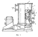
- FIG. 1 shows generally a screening apparatus 1 comprising an outer shell 2. Pulp is introduced into the screening apparatus through an inlet 3 from which it is passed into the inner space of a screen drum 4 disposed within the screening apparatus.
- the screen drum 4 is provided with openings 4a which may be holes or slits. An acceptable pulp fraction passed through the holes is discharged through a discharge opening 5 while a reject fraction containing shives, impurities, fibre bunches and other such too large particles is passed downward in the axial direction of the screen drum 4 so as to be removed through a reject opening 6.
- a rotor 7 comprising blades 8 is mounted within the screen drum 4 so as to rotate concentrically with the screen drum 4 about a shaft 9.
- the screening apparatus comprises a motor 10 arranged to rotate the rotor 7 by V belts or the like 11.
- the rotor 7 is shown from the side and in the direction of the shaft, respectively.
- the rotor 7 comprises a frame cylinder 7a and blades 8 attached to the frame cylinder at a distance from its surface by means of support arms 7b.
- Figure 3 shows in greater detail the position of one blade 8 with respect to the screen drum 4 and its holes 4a.
- the blade is triangular in shape and its front face forms in cross-section an acute angle with a blade face 8b facing the screen drum, that is, a sharp edge 8a.
- the blade is mounted so that the front face with the sharp edge moves first in the direction of travel.
- the blade face 8b facing the screen drum 4 is so positioned relative to the screen drum that its distance from the surface of the screen drum increases with the distance from the edge 8a, that is, backwards in the direction of travel.
- the blades 8 move along the surface of the screen drum 4, whereby the edge 8a of each blade 8 reaches each hole 4a at a frequency proportional to its rate of travel. If too long a shive or fibre is passing through the hole at the moment when the edge 8a of the blade 8 reaches the hole, the sharp edge 8a strikes the shive and displaces it with it so that it is returned to that side of the screen drum where the blades are positioned.
- the vacuum impulse created by the blade face 8b further facilitates the returning of the shive and the releasing of fibre bunches, shives, impurities and the like particles from the holes 4a.
- each blade 8 effects a similar phenomenon at each hole, so it can be predetermined on the basis of the number of the blades 8 and the rate of rotation of the rotor 7 what is the maximum length of acceptable fibres. If the flow rate Vm of the pulp in the hole 4a is one metre per second and the impact frequency of the blades 8 at each hole 4a is 100 Hz, determined by the rate of rotation Vs of the rotor and thus by the rate of travel of the blades, the maximum length of a fibre able to pass through one particular hole during the interval between the impacts of two successive blade edges is 10 mm whereas fibres and shives longer than that are pulled back inside the screen drum so as to be removed with the reject through the lower end of the screen drum.
- the size of the holes or slits of the screen drum can be considerably larger than previously because the screening capacity is not dependent on the size of the holes or slits only but it can be affected by suitably selecting the impact frequency of the blades.
- the cost of manufacture is decreased and the screening capacity can be increased while maintaining the same quality of pulp or even improving it.
- the blades of the screening apparatus can vary in shape and their shape can be closer to known blade shapes, provided that the edge of the blade is sharp in cross-section and moves closest to the surface of the screen drum, as described above.
- the blades need not be positioned on the inside of the screen drum as described above; they can be positioned on its outside as well, in which case the pulp to be screened is fed to the outer surface of the screen drum.
- the number of the blades can be selected as desired, provided that sufficiently space for a sufficiently free flow of pulp remains between them.
Landscapes
- Engineering & Computer Science (AREA)
- Mechanical Engineering (AREA)
- Paper (AREA)
- Combined Means For Separation Of Solids (AREA)
Applications Claiming Priority (2)
| Application Number | Priority Date | Filing Date | Title |
|---|---|---|---|
| FI890756 | 1989-02-16 | ||
| FI890756A FI80736B (fi) | 1989-02-16 | 1989-02-16 | Foerfarande foer sortering av massasuspension och sorteringsapparat. |
Publications (2)
| Publication Number | Publication Date |
|---|---|
| EP0383219A2 true EP0383219A2 (de) | 1990-08-22 |
| EP0383219A3 EP0383219A3 (de) | 1991-07-31 |
Family
ID=8527908
Family Applications (1)
| Application Number | Title | Priority Date | Filing Date |
|---|---|---|---|
| EP19900102656 Withdrawn EP0383219A3 (de) | 1989-02-16 | 1990-02-10 | Verfahren zum Sieben von Faserbrei und Siebvorrichtung |
Country Status (5)
| Country | Link |
|---|---|
| US (1) | US5071543A (de) |
| EP (1) | EP0383219A3 (de) |
| CA (1) | CA2010041A1 (de) |
| FI (1) | FI80736B (de) |
| NO (1) | NO900733L (de) |
Cited By (1)
| Publication number | Priority date | Publication date | Assignee | Title |
|---|---|---|---|---|
| EP0887459A1 (de) * | 1997-06-26 | 1998-12-30 | Voith Sulzer Papiertechnik Patent GmbH | Drucksortierer für Faserstoffsuspensionen |
Families Citing this family (9)
| Publication number | Priority date | Publication date | Assignee | Title |
|---|---|---|---|---|
| DE4308225C1 (de) * | 1993-03-16 | 1994-11-24 | Escher Wyss Gmbh | Verfahren zur Sortierung von Faserstoffsuspension sowie Siebvorrichtung zu seiner Durchführung |
| EP0663469A1 (de) * | 1994-01-18 | 1995-07-19 | Voith Sulzer Stoffaufbereitung GmbH | Rotor, insbesondere für einen Siebsortierer |
| FR2723543B1 (fr) * | 1994-08-10 | 1996-10-11 | Lamort E & M | Perfectionnements aux tamis cylindriques munis d'un rotor. |
| JP3286592B2 (ja) * | 1997-12-25 | 2002-05-27 | 相川鉄工株式会社 | 製紙用スクリーン装置 |
| ITVI20040208A1 (it) * | 2004-09-02 | 2004-12-02 | Comer Spa | Rotore perfezionato per epuratori di sospensioni fibrose |
| US20090020461A1 (en) * | 2005-05-09 | 2009-01-22 | Filtration Fibrewall Inc. | Screen Basket with Replaceable Profiled Bars |
| JP5465181B2 (ja) | 2007-11-14 | 2014-04-09 | フィルトレーション・ファイバーウォール・インコーポレーテッド | スクリーンバスケット |
| ITMI20110574A1 (it) * | 2011-04-08 | 2012-10-09 | Geolog S P A | Sistema di filtraggio e di campionamento continuo di un fango |
| MX2024006010A (es) | 2022-04-21 | 2024-05-30 | Kadant Black Clawson Llc | Rotor con puntales de barrido hacia adelante para cilindros de pantalla de presion. |
Family Cites Families (12)
| Publication number | Priority date | Publication date | Assignee | Title |
|---|---|---|---|---|
| US2230647A (en) * | 1938-07-09 | 1941-02-04 | Nelson M Knight | Pulp screening machine |
| US3255883A (en) * | 1963-02-18 | 1966-06-14 | Bird Machine Co | Pulp screen with discharge receptacle |
| DE1250726B (de) * | 1963-05-17 | 1967-09-21 | Canadian Ingersoll-Rand Company Limited, Montreal, Quebec (Kana da), Bird Machine Company, South Walpole, Mass (V St A) | Reinigungsvorrichtung fur Trommelsiebe |
| FI46642C (fi) * | 1972-02-03 | 1973-05-08 | Yhtyneet Paperitehtaat Oy | Painesihtilaite. |
| FI51221C (fi) * | 1972-06-21 | 1976-11-10 | Yhtyneet Paperitehtaat Oy | Painesihtilaite. |
| US3953325A (en) * | 1972-09-27 | 1976-04-27 | Nelson Douglas G | Pulp screen with rotating cleaning foil |
| US3970548A (en) * | 1973-08-27 | 1976-07-20 | The Black Clawson Company | Apparatus for screening paper fiber stock |
| DE2712715B2 (de) * | 1977-03-23 | 1979-05-23 | Hermann Finckh Maschinenfabrik Gmbh & Co, 7417 Pfullingen | Sortierer für Fasersuspensionen |
| FR2410081A1 (fr) * | 1977-11-23 | 1979-06-22 | Lamort Ingenieurs Construc E E | Appareil pour l'epuration des pates a papier |
| US4213823A (en) * | 1979-04-26 | 1980-07-22 | Beloit Corporation | Paper making machine screen with staggered foils |
| US4396502A (en) * | 1982-03-18 | 1983-08-02 | Beloit Corporation | Screening apparatus for a papermaking machine |
| US4919797A (en) * | 1989-02-09 | 1990-04-24 | The Black Clawson Company | Screening apparatus for paper making stock |
-
1989
- 1989-02-16 FI FI890756A patent/FI80736B/fi not_active Application Discontinuation
-
1990
- 1990-02-09 US US07/478,652 patent/US5071543A/en not_active Expired - Lifetime
- 1990-02-10 EP EP19900102656 patent/EP0383219A3/de not_active Withdrawn
- 1990-02-14 CA CA002010041A patent/CA2010041A1/en not_active Abandoned
- 1990-02-15 NO NO90900733A patent/NO900733L/no unknown
Cited By (1)
| Publication number | Priority date | Publication date | Assignee | Title |
|---|---|---|---|---|
| EP0887459A1 (de) * | 1997-06-26 | 1998-12-30 | Voith Sulzer Papiertechnik Patent GmbH | Drucksortierer für Faserstoffsuspensionen |
Also Published As
| Publication number | Publication date |
|---|---|
| NO900733D0 (no) | 1990-02-15 |
| FI890756A0 (fi) | 1989-02-16 |
| NO900733L (no) | 1990-08-17 |
| US5071543A (en) | 1991-12-10 |
| EP0383219A3 (de) | 1991-07-31 |
| CA2010041A1 (en) | 1990-08-16 |
| FI80736B (fi) | 1990-03-30 |
Similar Documents
| Publication | Publication Date | Title |
|---|---|---|
| CA1136585A (en) | High turbulence slotted circular screen with column-spaced rotating cleaners | |
| FI72358B (fi) | Silanordning foer sortering av pappersmassa | |
| US3581903A (en) | Separator for paper pulp suspensions | |
| US4188286A (en) | Screening apparatus for fiber suspensions | |
| EP0383219A2 (de) | Verfahren zum Sieben von Faserbrei und Siebvorrichtung | |
| US4919797A (en) | Screening apparatus for paper making stock | |
| US4447320A (en) | Device for cleaning and recovering paper pulp | |
| EP0634259A2 (de) | Verfahren und Vorrichtung zum Rückgewinnen von Komponenten von stabförmigen Körpern der tabakverarbeitenden Industrie | |
| JP3542594B2 (ja) | 繊維懸濁液用加圧分離装置 | |
| US4396161A (en) | Disk refiner | |
| US3845863A (en) | Pulp sifter with cleaning means | |
| GB1584574A (en) | Method and apparatus for pulping and grading waste material | |
| DE60105359T3 (de) | Sortierapparat für eine Fasersuspension | |
| US2460938A (en) | Method and apparatus for cleaning asbestos | |
| EP0894892A1 (de) | Verfahren und Flotationsvorrichtung zur Entfernung von Störstoffen aus einer wässrigen Faserstoffsuspension | |
| US3409132A (en) | Screen plate for centrifugal pulp screens | |
| RU1838469C (ru) | Чесальна машина | |
| JPS62503109A (ja) | 輪郭表面を有するスクリ−ニング装置に使用される回転要素 | |
| EP0952244B1 (de) | Vorrichtung zum Öffnen und Schmutzausscheiden für Textilflockenmaterialöffner oder -karden | |
| US3373875A (en) | Apparatus for screening pulp | |
| SE434529B (sv) | Silanordning | |
| RU2002100085A (ru) | Способ и устройство для получения бумажной массы из старой бумаги | |
| US4472859A (en) | Card screen assembly | |
| EP0402237B1 (de) | Drucksiebvorrichtung | |
| EP2714988B1 (de) | Fasersortierung |
Legal Events
| Date | Code | Title | Description |
|---|---|---|---|
| PUAI | Public reference made under article 153(3) epc to a published international application that has entered the european phase |
Free format text: ORIGINAL CODE: 0009012 |
|
| AK | Designated contracting states |
Kind code of ref document: A2 Designated state(s): AT DE FR GB SE |
|
| PUAL | Search report despatched |
Free format text: ORIGINAL CODE: 0009013 |
|
| AK | Designated contracting states |
Kind code of ref document: A3 Designated state(s): AT DE FR GB SE |
|
| STAA | Information on the status of an ep patent application or granted ep patent |
Free format text: STATUS: THE APPLICATION HAS BEEN WITHDRAWN |
|
| 18W | Application withdrawn |
Withdrawal date: 19911031 |