EP0383334B1 - Elektromagnetische Heizvorrichtung - Google Patents
Elektromagnetische Heizvorrichtung Download PDFInfo
- Publication number
- EP0383334B1 EP0383334B1 EP90102983A EP90102983A EP0383334B1 EP 0383334 B1 EP0383334 B1 EP 0383334B1 EP 90102983 A EP90102983 A EP 90102983A EP 90102983 A EP90102983 A EP 90102983A EP 0383334 B1 EP0383334 B1 EP 0383334B1
- Authority
- EP
- European Patent Office
- Prior art keywords
- cavity resonator
- electric field
- heating device
- frequency
- electromagnetic heating
- Prior art date
- Legal status (The legal status is an assumption and is not a legal conclusion. Google has not performed a legal analysis and makes no representation as to the accuracy of the status listed.)
- Expired - Lifetime
Links
- 238000010438 heat treatment Methods 0.000 title claims abstract description 55
- 230000005684 electric field Effects 0.000 claims abstract description 62
- 239000000463 material Substances 0.000 claims abstract description 4
- 230000005672 electromagnetic field Effects 0.000 claims abstract 2
- 239000003990 capacitor Substances 0.000 claims description 19
- 230000008859 change Effects 0.000 abstract description 9
- 230000005540 biological transmission Effects 0.000 abstract description 6
- 239000012141 concentrate Substances 0.000 abstract description 4
- 238000004519 manufacturing process Methods 0.000 abstract description 2
- 238000007493 shaping process Methods 0.000 abstract 1
- 206010028980 Neoplasm Diseases 0.000 description 3
- 201000011510 cancer Diseases 0.000 description 3
- 239000004020 conductor Substances 0.000 description 3
- 230000007246 mechanism Effects 0.000 description 3
- 238000010586 diagram Methods 0.000 description 2
- 239000003989 dielectric material Substances 0.000 description 2
- 230000000694 effects Effects 0.000 description 2
- 238000000034 method Methods 0.000 description 2
- 230000001225 therapeutic effect Effects 0.000 description 2
- 0 **1CCCC1 Chemical compound **1CCCC1 0.000 description 1
- 230000009471 action Effects 0.000 description 1
- 230000008901 benefit Effects 0.000 description 1
- 230000002349 favourable effect Effects 0.000 description 1
- 238000002347 injection Methods 0.000 description 1
- 239000007924 injection Substances 0.000 description 1
- 238000005259 measurement Methods 0.000 description 1
- 230000010355 oscillation Effects 0.000 description 1
- 230000008569 process Effects 0.000 description 1
- 230000009467 reduction Effects 0.000 description 1
Images


Classifications
-
- A—HUMAN NECESSITIES
- A61—MEDICAL OR VETERINARY SCIENCE; HYGIENE
- A61F—FILTERS IMPLANTABLE INTO BLOOD VESSELS; PROSTHESES; DEVICES PROVIDING PATENCY TO, OR PREVENTING COLLAPSING OF, TUBULAR STRUCTURES OF THE BODY, e.g. STENTS; ORTHOPAEDIC, NURSING OR CONTRACEPTIVE DEVICES; FOMENTATION; TREATMENT OR PROTECTION OF EYES OR EARS; BANDAGES, DRESSINGS OR ABSORBENT PADS; FIRST-AID KITS
- A61F7/00—Heating or cooling appliances for medical or therapeutic treatment of the human body
- A61F2007/009—Heating or cooling appliances for medical or therapeutic treatment of the human body with a varying magnetic field acting upon the human body, e.g. an implant therein
Definitions
- the present invention relates to an electromagnetic heating device using a cavity resonator for heating a living body or an object, and in particular to an electromagnetic heating device which may be advantageously used for heating a living object, for instance for the treatment of cancer and other ailments.
- Cavity resonators have been conventionally used in electromagnetic heaters for heating living bodies and objects.
- a pair of projections (reentrants) 4a and 4b are integrally provided in the upper and lower internal walls 2a and 2b of a cavity resonator 1 consisting of a cylindrical metallic conductor, and a pair of openings 3a and 3b are provided in its side wall 6 to introduce a living body 5 or an object thereinto.
- High frequency electromagnetic energy is supplied to the cavity resonator 1 from outside.
- a link coil as means for adjusting the resonant frequency of the cavity resonator and achieving an efficient transmission of high frequency energy into the cavity resonator.
- the use of a link coil does not necessarily ensure an efficient supply of high frequency energy because a change in the resonant frequency of the cavity resonator produces a change in the impedance of the cavity resonator as seen from the high frequency electromagnetic energy source.
- a primary object of the present invention is to provide an electromagnetic heating device using a cavity resonator which can transmit high frequency electromagnetic energy to an object to be heated at a high efficiency even when the conditions of the object has changed, and can thereby ensure an efficient transmission of electromagnetic energy to the object.
- a second object of the present invention is to provide an electromagnetic heating device which can concentrate electromagnetic energy to a small region inside the object to be heated.
- a third object of the present invention is to provide an electromagnetic heating device which can heat an internal part of an object without excessively raising its surface temperature.
- a fourth object of the present invention is to provide an electromagnetic heating device which is simple in structure yet is capable of transmitting high frequency energy to an object to be heated at high efficiency irrespective of the conditions of the object to be heated.
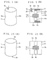
- Figure 1(A) is a perspective external view of a cavity resonator 11 of an electromagnetic heating device constructed as an embodiment of the present invention
- Figure 1(B) is a longitudinal sectional view of the cavity resonator 11.
- the cavity resonator 11 is a cylindrical body made of a metallic conductor, and is provided with openings 13a and 13b in its side wall 16 to introduce a living body or an object 15 thereinto. Further, the cavity resonator 11 is internally provided with electric field concentrators 14a and 14b.
- These electric field concentrators 14a and 14b are not exactly integral with upper and lower walls 12a and 12b of the cavity resonator 11, but supported thereby by way of support means (now shown in the drawings) so as to be electrically separated from each other.
- a pair of frequency adjustors 17a and 17b are provided between the upper and lower walls 12a and 12b of the cavity resonator 11 and the associated electric field concentrators 14a and 14b, respectively, so that the frequency of the cavity resonator 11 may be adjusted by changing their thicknesses and relative dielectric constants.
- the resonant frequency is too high, it may be lowered by increasing the thicknesses of the frequency adjustors 17a and 17b and/or by using a material having a large relative dielectric constant for the frequency adjustors 17a and 17b. Conversely, if the resonant frequency is too low, the thicknesses of the frequency adjustors 17a and 17b may be reduced or a material having a lower relative dielectric constant may be used.
- the upper wall 12a of the cavity resonator 11 is externally provided with a connector 18, and is internally provided with a link coil 20, adjacent to the electric field concentrator 14a, which is connected to the upper wall 12a at its one end and to a signal terminal of the connector 18 via a variable capacitor 19 at its other end.
- the variable capacitor 19 serves as a capacitor (impedance matching element) for impedance matching.
- variable capacitor 19 is connected between the connector 18 and the link coil 20 as an impedance matching element.
- variable capacitor 19 is connected between the connector 18 and the link coil 20.
- the variable capacitor 19 is disposed adjacent to the upper wall in the cavity resonator 11 in this embodiment, but it may also be placed on the upper wall outside the cavity resonator 11.
- the cavity resonator 11 was provided with a pair of electric field concentrators 14a and 14b and is constructed as a cylindrical body so that a living body 15 may be placed in the space defined between the electric field concentrators 14a and 14b.
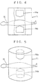
- the cavity resonator of the present invention is not limited to a cylindrical shape, but may also have rectangular and other shapes. It may be provided with at least one electric field concentrator 14 as illustrated in Figure 2, may comprises a frequency adjustor 17 between the electric field concentrator 14 and a bottom wall of the cavity resonator 11 as shown in Figure 3, or may comprise a pair of electric field concentrators 14a and 14b to place a living body or an object to be heated therebetween as illustrated in Figure 4.
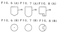
- the free end of the electric field concentrator 14 may be sharply tapered as shown in Figures 6(A) and 6(B), rounded to a spherical shape as shown in Figures 7(A) and 7(B), or shaped into a special shape which corresponds to a desired heating pattern as shown in Figures 8(A) and 8(B).
- Figure 9 shows a structure in which the relative position between the electric field concentrator 14 and the frequency adjustor 17 can be varied.
- the frequency adjustor 17 is provided with a rack which may be driven by a gear 172 so that the frequency adjustor 17 may be moved by rotating the gear 172 mounted on the bottom wall 12.
- Figure 10 shows a structure in which the frequency adjustor 17 is provided with the shape of a fan, and the base end of this fan shape 173 is pivotably secured in a rotatable fashion so that the free end of the frequency adjustor 17 may be rotated.
- the relative position between the electric field concentrator 14 and the frequency adjustor 17 can be changed, and the areas of their mutually opposing surfaces can be changed.
- the resonant frequency of the overall cavity resonator 11 can be changed.
- the areas of the opposing surfaces may be increased to thereby lower the resonant frequency.
- the areas of the mutually opposing surfaces may be reduced to thereby raise the resonant frequency.
- the electric field concentrator 14 is made up of a pair of conductive cylinders 141 and 143, and a metallic spring 142 interposed between the inner conductive cylinder 141 and the outer conductive cylinder 143 so as to ensure a favorable electric conduction therebetween.
- the electric field concentrators 141 and 143 can be moved and deformed. Their overall volume may be changed simply by pulling or pushing the conductive cylinder 143 of the electric field concentrator 14 relative to the other conductive cylinder 141 by hand or by some other means.
- the electric field concentrator 14 is accommodated in the cavity resonator 11, and occupies a part of its internal space. By increasing this occupied space, the resonant frequency of the cavity resonator may be lowered.
- the resonant frequency of the cavity resonator 11 can be lowered by increasing the overall volume of the conductive cylinders 141 and 143 of the electric field concentrator 14 by stretching the conductive cylinders 141 and 143, and this process may also be reversed. In short, the resonant frequency of the cavity resonator can be adjusted.
- the bottom wall 12 or the side wall 16 of the cavity resonator 11 and the electric field concentrator 14 are connected to each other by a coil 173.
- the bottom wall 12 of the cavity resonator 11 and the electric field concentrator 14 are connected to each other by a conductive rod 174.
- the resonant frequency of a cavity resonator may be lowered by inserting the coil 173 between the wall surface of the cavity resonator and the electric field concentrator 14.
- the resonant frequency of the cavity resonator can be changed.
- shrinking the coil its inductance is increased, and the resonant frequency of the cavity resonator is lowered.
- the resonant frequency may be raised. In a high frequency range, an inductance is produced even when conductive wires or conductive rods are used instead of a coil, and the resonant frequency may be adjusted according to the thickness of the conductive wires or the conductive rods and their number.
- the inductance diminishes, and the resonant frequency rises.
- the resonant frequency may be further adjusted.
- the resonant frequency of the cavity resonator 11 can be lowered by adding a coil, and a low resonant frequency can be achieved while keeping the diameter of the cavity resonator the same.
- an oscillator for a lower frequency is more economical, and this method allows the device to be manufactured economically.
- Figure 14 shows an example of a mode of supporting the electric field concentrator 14.
- the electric field concentrator 14 is supported by a bottom wall 12 and side walls 16 by way of wires 51, 52 and 53 made of dielectric material.
- the electric field concentrator 14 may be moved vertically and laterally by pulling and paying out these wires 51, 52 and 53 by pulleys or electric motors 54, 55 and 56. It is also possible to move the electric field concentrator 14 by securing the electric field concentrator 14 with a dielectric rod instead of the wires 51, 52 and 53, and moving this dielectric rod vertical and laterally.
- the electric field concentrator out of two or more parts each of which is partially secured and allowed to move only at its free end.
- the position of the electric field concentrator By changing the position of the electric field concentrator, it is possible to change the pattern of the electric current injected from the free end thereof. Therefore, when the location to be heated is desired to be changed only slightly, it can be accomplished without moving the living body or the object. If there is any inconvenience in changing the resonant frequency and/or the impedance by moving the electric field concentrator, the position to be heated can be changed without substantially affecting the resonant frequency and the impedance by constructing the electric field concentrator from two or more parts which are partially secured so as to permit the movement of their free ends.
- an accurate positioning of the part to be heated is possible, and a high therapeutic effect may be achieved in case of heating a living body.
- a living body is to be interposed between a pair of moveable electric field concentrators (which may be moveable only at their free ends), even when the electric field concentrators are moved, a desired position to be heated deep inside the living body can be always heated and the deep body part can be heated to a high temperature as long as the electric field concentrators are moved appropriately in different directions while the electric current flow pattern on the body surface keeps changing and prevents any excessive rise in the surface temperature.
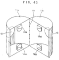
- the cavity resonator 11 of the above described embodiment consisted of a single body, but may also be divided by vertical parting lines into a pair of semi-cylindrical parts 11a and 11b which are joined by a connecting part (hinge) 111 so that one of them may be opened and closed with respect to the other as illustrated in Figure 15.
- the electric field concentrators are also divided into two parts 14aa and 14ab, and 14ba and 14bb.
- the cavity resonator it is possible to place a large living body or a large object into the cavity resonator not only through the opening 13 but also by opening the semi-cylindrical parts 11a and 11b without any difficulty.
- the cavity resonator When the cavity resonator is to be divided, it should be divided by a vertical parting line because of the consideration not to obstruct electric current which flows vertically along the wall surface 16 inside the cavity resonator. In this case, the change in the resonant frequency may be minimized even when the connection by the connecting piece may be insufficient. Also, the loss is minimized.
- a large living body or a large object can be easily accommodated in the cavity resonator without increasing a loss or affecting the resonant frequency.
- the electromagnetic heating device illustrated in Figure 16 comprises a table 40 for securely supporting a living body 15, and a mechanism 41 which supports a cavity resonator 11 in a rotatable fashion relative to the table 40.
- the cavity resonator 11 itself may consist of the one illustrated in Figure 1(B).
- the rotating mechanism 41 consists of a C arm 42 carrying the cavity resonator 11 by way of support rods 44 at its both ends, and a drive unit 43 for rotating this C arm 42.
- the distribution of electric current on the surface of the living body 15 varies depending on the angle of the cavity resonator 11, but electric current is always supplied to cancerous tissues in the center of the living body to effectively heat them. Therefore, a concentrated heating effect can be obtained without excessively heating the surface, and a significant advantage can be gained in the field of cancer treatment.
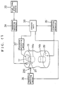
- FIG 17 is a block diagram of yet another embodiment of the electromagnetic heating device.
- This electromagnetic heating device comprises a high frequency power source unit 33, a cavity resonator 11, a impedance matching condition detector 34, a resonant condition detector 35, a impedance matching condition adjusting motor 36, a frequency adjusting motor 37, and a control unit 38 which controls the impedance matching adjusting motor 36 according to the impedance matching condition detected by the impedance matching condition detector 34 and the frequency adjusting motor 37 according to the resonant condition detected by the resonant condition detector 35.
- the cavity resonator 11 incorporates therein a pair of electric field concentrators 14a and 14b, a frequency adjustor 17, a link coil 20, and a position varying unit 200 adjusting the position of the link coil 20 relative to the electric field concentrator 14a (refer to Figure 6) which is given here as an example of the impedance matching unit, as well as a link coil 39 for detecting a resonant condition.
- high frequency energy is supplied from the high frequency power source 33 to the cavity resonator 11.
- the impedance matching condition between the link coil 20 of the cavity resonator 11 and the high frequency power source unit 33 is detected by the impedance matching condition detector 34, and the control unit 38 automatically adjusts the impedance matching condition adjusting motor 36 according to the detected impedance matching condition so as to achieve an optimum impedance matching condition.
- a voltage in the cavity resonator 11 may be obtained by the link coil 39 as a measurement sample for the resonant condition detector 35, and the control unit 38 controls the frequency adjusting motor 37 and finely adjusts the frequency adjustor 17 so as to match the resonant frequency of the cavity resonator 11 with the frequency of the high frequency power source unit 33 and obtain a maximum detected output.
- the resonant frequency of the cavity resonator is automatically matched with the frequency of the high frequency power source unit, high frequency electric power is always effectively injected. Further, a perfect impedance matching condition can be automatically attained between the link coil of the cavity resonator and the high frequency power source unit, and this also contributes to an effective injection of high frequency energy.
- the electric field concentrators were electrically out of contact with the frequency adjustor, but the present invention is not limited to these embodiments but is applicable to an embodiment integrally combining a frequency adjustor and an electric field concentrator. Further, instead of adjusting the frequency of the cavity resonator, it is possible to adjust the frequency of the high frequency power source with manual or other means as well know to persons skilled in the art.
- variable capacitor 19 is connected between the connector 18 and the link coil 20 as a matching unit.
- the variable capacitor 19 is disposed externally of the upper wall of the cavity resonator 11, but it may also be placed internally of the upper wall of the cavity resonator 11.
- the resonant frequency of the link coil 20 is varied so as to coincide with the resonant frequency of the cavity resonator 11.
- the impedance of the circuit consisting of the link coil 20 and the variable capacitor 19 coincides with that of the feeder cable, high frequency energy is most efficiently supplied to the cavity resonator 11.
- variable capacitors 19a and 19b may be utilized to match the resonant frequency of the link coil 20 and divide the impedance into a value which matches with the impedance of the feeder cable as shown in Figures 20 and 21. If the variable capacitors 19, 19a and 19b are placed remote from the link coil 20, since the cable extending therebetween is in a condition of impedance mismatch, flow of high frequency current is disturbed and heat is generated thereby with the result that the high frequency electromagnetic energy is not efficiently transmitted to the cavity resonator 11. To prevent this from occurring, the variable capacitors 19, 19a and 19b are placed adjacent to the link coil 20.
- high frequency energy can be efficiently supplied to the cavity resonator since the resonant condition of the link coil for supplying high frequency energy to the cavity resonator can be achieved and the impedance thereof can be matched with that of the feeder cable by the use of a variable capacitor. As a result, the living body of the object placed in the cavity resonator can be effectively heated.
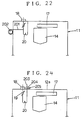
- Figure 22 shows a cavity resonator 11 for the electromagnetic heating device in which a length of non-conductive wire 201 is attached to the link coil 20, and the other end of the wire is wound or paid out by a pulley or a motor 202 from outside the cavity resonator 11 so that the distance between the link coil 20 and the electric field concentrator 14 may be adjusted.
- This is also applicable to the case in which only a link coil 20 is used as is the case with the embodiment illustrated in Figure 18, and the impedance of the link coil 20 does not match with that of the feeder cable.
- the impedance of the link coil 20 is modified. If the link coil 20 is brought closer to and further away from the electric field concentrator 14, the impedance of the link coil 20 diminishes and increases, respectively. Therefore, by moving the link coil 20 a suitable distance away from the electric field concentrator 14, it is possible to achieve an impedance matching between the link coil 20 and the electric field concentrator 14.
- Figure 23 shows another embodiment in which the distance between the link coil 20 and the electric field concentrator 14 is made variable.
- a connector 18, a variable capacitor 19 and a link coil 20 are incorporated in a mount 182 which is made moveable along a slot 181 provided in a bottom wall 12 of the cavity resonator 11.
- Figure 24 shows another embodiment for achieving an impedance matching.
- a free end 203 of a link coil 20 is allowed to be moved into and out of a cavity resonator 11 from its upper end wall 12a, and a part of the free end 203 of the link coil 20 may be fixedly secured by a clamp member 204 and a fixing screw 205.
- the resonant frequency and the impedance of the link coil 20 can be changed.
- a variable capacitor 19 it is possible to achieve resonant condition and impedance matching.
- the resonant condition of the link coil for supplying high frequency energy to the cavity resonator can be attained, and the impedance of the link coil can be matched with that of the feeder cable, high frequency energy can be effectively supplied to the cavity resonator.
- a living body or an object placed in the cavity resonator can be effectively heated.
- a strong current may be concentrated in the part to be heated, and the thermal action of the electric current heats this part to a high temperature. Therefore, the temperature rise in parts having a small electric current concentration is minimized, and a highly concentrated heating is made possible. Further, since the electric field concentrator and the cavity resonator are electrically out of contact with each other, it is possible to interpose a frequency adjustor therebetween, and allow the resonant frequency of the cavity resonator to be adjustable.
- an electric field concentrator which is electrically out of contact with the cavity resonator, and a frequency adjusting means, when a living body is placed in the cavity resonator and the resonant frequency of the cavity resonator is affected by the size of the living body, it can be adjusted to a fixed value by using the frequency adjusting means. Therefore, the frequency of the high frequency power source unit may be fixed, and it becomes possible to achieve a drastic reduction in the overall cost of the heating device and to diminish interferences to radio communications.
- an optimum impedance matching condition can be automatically achieved by the use of the link coil for detecting a signal in the cavity resonator, the resonance detector for picking up the signal from the link coil, and the control unit which controls the frequency adjusting means according to the resonance output, it is possible to achieve an optimum resonant condition and an optimum heating condition by adjusting the frequency adjusting means even when the frequency changes due to the change in the size or the position of the living body or the object so as to offer an effective electromagnetic heating device.
- the matching unit is provided adjacent to the link coil inside or outside of the cavity resonator, high frequency energy can be transmitted at a high efficiency. Furthermore, since the matching unit is provided adjacent to the link coil, there is very little energy loss in the path therebetween, and this also contributes to an efficient transmission of high frequency energy.
- an optimum impedance matching condition can be automatically achieved by the use of the control unit which controls the impedance matching condition adjusting means, no effort is required to obtain a matched condition of impedance, and supply of high frequency energy can be achieved in an optimum condition.
Landscapes
- Health & Medical Sciences (AREA)
- Animal Behavior & Ethology (AREA)
- Public Health (AREA)
- Heart & Thoracic Surgery (AREA)
- Vascular Medicine (AREA)
- Life Sciences & Earth Sciences (AREA)
- Engineering & Computer Science (AREA)
- General Health & Medical Sciences (AREA)
- Biomedical Technology (AREA)
- Veterinary Medicine (AREA)
- Electrotherapy Devices (AREA)
- Radiation-Therapy Devices (AREA)
- Surgical Instruments (AREA)
- Cookers (AREA)
- Yarns And Mechanical Finishing Of Yarns Or Ropes (AREA)
Claims (8)
- Elektromagnetische Heizvorrichtung zum Erwärmen eines lebenden Körpers oder eines Gegenstands, mit
einem Hohlraumresonator (11) aus einem hohlen elektrisch leitfähigen Material zur Aufnahme eines lebenden Körpers oder eines Gegenstands und Erwärmung desselben durch ein darin erzeugtes elektromagnetisches Hochfrequenzfeld, und
wenigstens einem elektrischen Feldkonzentrator (14, 14a, 14b), der in dem Hohlraumresonator (11) angeordnet ist, gekennzeichnet durch
Resonanzfrequenzeinstellmittel mit einer an ein Eingangsende des Hohlraumresonators (11) angeschlossenen Verbindungsspule (20),
Impedanzanpassungsmittel (19), die benachbart zu der Verbindungsspule angeordnet sind, und
dadurch daß wenigstens ein elektrischer Feldkonzentrator (14, 14a, 14b) in dem Hohlraumresonator (11) getrennt davon so angeordnet ist, daß ein Frequenzeinsteller (17, 17a, 17b, 175) zwischen dem elektrischen Feldkonzentrator (14, 14a, 14b) und dem Hohlraumresonator angeordnet werden kann, oder so, daß der elektrische Feldkonzentrator (14) in Bezug auf den Hohlraumresonator (11) beweglich ist. - Elektromagnetische Heizvorrichtung nach Anspruch 1, wobei der elektrische Feldkonzentrator einen rohrförmigen Körper (14) mit einem Vorsprung an seinem freien Ende aufweist.
- Elektromagnetische Heizvorrichtung nach Anspruch 1, wobei der elektrische Feldkonzentrator ein Paar von elektrischen Konzentrierungselementen (14a, 14b) aufweist, die voneinander im Abstand liegen und einen Raum zur Aufnahme eines zu erwärmenden lebenden Körpers oder Gegenstands dazwischen definieren.
- Elektromagnetische Heizvorrichtung nach irgendeinem der vorstehenden Ansprüche, wobei die Impedanzanpassungsmittel einen veränderbaren Kondensator (19) aufweisen.
- Elektromagnetische Heizvorrichtung nach irgendeinem der vorstehenden Ansprüche, wobei die Impedanzanpassungsmittel Mittel (26, 200) zum Bewegen der Verbindungsspule (20) aufweisen.
- Elektromagnetische Heizvorrichtung nach irgendeinem der vorstehenden Ansprüche, welche ferner
eine Abnahmespule (39) zum Abnehmen eines Signals in dem Hohlraumresonator (11),
Resonanzbedingungsnachweismittel (35) zum Nachweisen eines von der Abnahmespule (39) ausgegebenen Signals, und
Steuermittel (38) zum Steuern von Bewegungsmitteln (37) zum Bewegen des Frequenzeinstellers gemäß Ausgaben der Resonanzbedingungsnachweismittel (35) aufweist. - Elektromagnetische Heizvorrichtung nach Anspruch 6, welche ferner Mittel (34) zum Feststellen einer Impedanzanpassungsbedingung und Mittel (36) zum Einstellen der Impedanzanpassungsbedingung aufweist, wobei die Steuermittel (38) sowohl die Bewegungsmittel (37) als auch die Mittel (36) zur Einstellung der Impedanzanpassungsbedingung gemäß Ausgaben der Resonanzbedingungsnachweismittel (35) und der Impedanzanpassungsbedingungsnachweismittel (34) steuern.
- Elektromagnetische Heizvorrichtung nach irgendeinem der vorstehenden Ansprüche, welche ferner bewegliche Trägermittel (43) zum Bewegen des Hohlraumresonators (11) in Bezug auf einen zu erwärmenden lebenden Körper oder Gegenstand aufweist.
Applications Claiming Priority (4)
| Application Number | Priority Date | Filing Date | Title |
|---|---|---|---|
| JP36601/89 | 1989-02-16 | ||
| JP36600/89 | 1989-02-16 | ||
| JP3660089A JP2807479B2 (ja) | 1989-02-16 | 1989-02-16 | 電磁波加温装置 |
| JP1036601A JP2807480B2 (ja) | 1989-02-16 | 1989-02-16 | 電磁波加温装置 |
Publications (3)
| Publication Number | Publication Date |
|---|---|
| EP0383334A2 EP0383334A2 (de) | 1990-08-22 |
| EP0383334A3 EP0383334A3 (de) | 1991-03-13 |
| EP0383334B1 true EP0383334B1 (de) | 1996-06-19 |
Family
ID=26375675
Family Applications (1)
| Application Number | Title | Priority Date | Filing Date |
|---|---|---|---|
| EP90102983A Expired - Lifetime EP0383334B1 (de) | 1989-02-16 | 1990-02-15 | Elektromagnetische Heizvorrichtung |
Country Status (4)
| Country | Link |
|---|---|
| US (1) | US5163446A (de) |
| EP (1) | EP0383334B1 (de) |
| AT (1) | ATE139455T1 (de) |
| DE (1) | DE69027459T2 (de) |
Families Citing this family (8)
| Publication number | Priority date | Publication date | Assignee | Title |
|---|---|---|---|---|
| JP2888608B2 (ja) * | 1990-06-01 | 1999-05-10 | 義明 齊藤 | 電磁波加温装置 |
| US5492122A (en) * | 1994-04-15 | 1996-02-20 | Northrop Grumman Corporation | Magnetic resonance guided hyperthermia |
| US5690109A (en) * | 1995-06-23 | 1997-11-25 | Govind; Rakesh | Method of destructive, noninvasive hyperpyrexia of tissues and organisms utilizing nuclear magnetic resonance |
| JP3477514B2 (ja) * | 2000-07-04 | 2003-12-10 | 新潟大学長 | 癌温熱治療装置 |
| JP3493428B2 (ja) * | 2000-07-04 | 2004-02-03 | 新潟大学長 | 癌温熱治療装置 |
| DE102005007851A1 (de) * | 2005-02-21 | 2006-08-24 | Siemens Ag | Bestrahlungsvorrichtung |
| CN102740519A (zh) * | 2012-07-05 | 2012-10-17 | 西北核技术研究所 | 一种生物大体射频加热方法及装置 |
| WO2018102734A1 (en) * | 2016-12-01 | 2018-06-07 | Spot Labs, Llc | System and method for electromagnetic oven heating energy control using active and passive elements |
Family Cites Families (6)
| Publication number | Priority date | Publication date | Assignee | Title |
|---|---|---|---|---|
| AT216665B (de) * | 1959-01-21 | 1961-08-10 | Siemens Reiniger Werke Ag | Elektrode zur Erzeugung eines hochfrequenten Feldes für die Durchwärmung von biologischen Geweben |
| DE2420883A1 (de) * | 1974-04-30 | 1975-11-13 | Guettner Tronado | Elektromedizinische bestrahlungsapparatur zur krebsheilung durch hochfrequenzextremhyperthermie-therapie |
| LU70345A1 (de) * | 1974-06-18 | 1976-05-31 | ||
| US4434341A (en) * | 1980-02-20 | 1984-02-28 | Busby Dennis L | Selective, locally defined heating of a body |
| JPS60198089A (ja) * | 1984-03-22 | 1985-10-07 | 丸山 悠司 | 生化学用供試体容器 |
| JP2614887B2 (ja) * | 1988-02-18 | 1997-05-28 | 甚一 松田 | 局所加温装置及び局所加温用の立体共振器 |
-
1990
- 1990-02-15 AT AT90102983T patent/ATE139455T1/de not_active IP Right Cessation
- 1990-02-15 DE DE69027459T patent/DE69027459T2/de not_active Expired - Fee Related
- 1990-02-15 EP EP90102983A patent/EP0383334B1/de not_active Expired - Lifetime
- 1990-08-16 US US07/568,141 patent/US5163446A/en not_active Expired - Fee Related
Also Published As
| Publication number | Publication date |
|---|---|
| ATE139455T1 (de) | 1996-07-15 |
| DE69027459T2 (de) | 1997-02-20 |
| EP0383334A3 (de) | 1991-03-13 |
| EP0383334A2 (de) | 1990-08-22 |
| US5163446A (en) | 1992-11-17 |
| DE69027459D1 (de) | 1996-07-25 |
Similar Documents
| Publication | Publication Date | Title |
|---|---|---|
| EP0647975B1 (de) | Dielektrischer Resonator, dielektrisches Bandsperrfilter und dielektrisches Filter | |
| EP0383334B1 (de) | Elektromagnetische Heizvorrichtung | |
| US4922180A (en) | Controlled microwave sample irradiation system | |
| US5186181A (en) | Radio frequency thermotherapy | |
| US7957815B2 (en) | Electrode assembly and handpiece with adjustable system impedance, and methods of operating an energy-based medical system to treat tissue | |
| RU95112666A (ru) | Антенное устройство для прибора радиосвязи | |
| JPS59134591A (ja) | マイクロ波エネルギー用移相装置およびマイクロ波調理用空胴の励振システム | |
| EP1118134B1 (de) | Koaxialer hohlraumresonator | |
| JP3249701B2 (ja) | 誘電加熱装置 | |
| KR20010112362A (ko) | 고주파필터 | |
| KR920006757B1 (ko) | 전자파가온장치 | |
| US5412182A (en) | Eddy current heating for hyperthermia cancer treatment | |
| US3422240A (en) | Microwave oven | |
| JP3640621B2 (ja) | 誘電加熱装置 | |
| KR920006758B1 (ko) | 전자파가온장치 | |
| JP2807479B2 (ja) | 電磁波加温装置 | |
| US20030047558A1 (en) | Device for heating metallic items | |
| DK174056B1 (da) | Fremgangsmåde og apparat til opvarmning af medier ved hjælp af højfrekvente elektromagnetiske bølger | |
| JP4171559B2 (ja) | 超短波治療器用導子 | |
| JP2000196337A (ja) | アンテナ装置 | |
| CN1260084A (zh) | 连续可调的谐振器 | |
| RU226347U1 (ru) | Укороченный малогабаритный локомотивный излучатель гектометровых волн | |
| JPH0546509B2 (de) | ||
| SU836822A1 (ru) | Установка дл локального высокочастотногоНАгРЕВА дЕТАлЕй из пРОВОд щиХ МАТЕРиАлОВ | |
| KR100392233B1 (ko) | 고출력 수냉식 위상 가변기 |
Legal Events
| Date | Code | Title | Description |
|---|---|---|---|
| PUAI | Public reference made under article 153(3) epc to a published international application that has entered the european phase |
Free format text: ORIGINAL CODE: 0009012 |
|
| 17P | Request for examination filed |
Effective date: 19900215 |
|
| AK | Designated contracting states |
Kind code of ref document: A2 Designated state(s): AT BE CH DE DK ES FR GB GR IT LI NL SE |
|
| PUAL | Search report despatched |
Free format text: ORIGINAL CODE: 0009013 |
|
| AK | Designated contracting states |
Kind code of ref document: A3 Designated state(s): AT BE CH DE DK ES FR GB GR IT LI NL SE |
|
| RHK1 | Main classification (correction) |
Ipc: A61N 5/02 |
|
| 17Q | First examination report despatched |
Effective date: 19930601 |
|
| GRAH | Despatch of communication of intention to grant a patent |
Free format text: ORIGINAL CODE: EPIDOS IGRA |
|
| GRAA | (expected) grant |
Free format text: ORIGINAL CODE: 0009210 |
|
| AK | Designated contracting states |
Kind code of ref document: B1 Designated state(s): AT BE CH DE DK ES FR GB GR IT LI NL SE |
|
| PG25 | Lapsed in a contracting state [announced via postgrant information from national office to epo] |
Ref country code: NL Free format text: LAPSE BECAUSE OF FAILURE TO SUBMIT A TRANSLATION OF THE DESCRIPTION OR TO PAY THE FEE WITHIN THE PRESCRIBED TIME-LIMIT Effective date: 19960619 Ref country code: LI Effective date: 19960619 Ref country code: GR Free format text: LAPSE BECAUSE OF FAILURE TO SUBMIT A TRANSLATION OF THE DESCRIPTION OR TO PAY THE FEE WITHIN THE PRESCRIBED TIME-LIMIT Effective date: 19960619 Ref country code: ES Free format text: THE PATENT HAS BEEN ANNULLED BY A DECISION OF A NATIONAL AUTHORITY Effective date: 19960619 Ref country code: DK Effective date: 19960619 Ref country code: CH Effective date: 19960619 Ref country code: BE Effective date: 19960619 Ref country code: AT Effective date: 19960619 |
|
| REF | Corresponds to: |
Ref document number: 139455 Country of ref document: AT Date of ref document: 19960715 Kind code of ref document: T |
|
| ITF | It: translation for a ep patent filed | ||
| REF | Corresponds to: |
Ref document number: 69027459 Country of ref document: DE Date of ref document: 19960725 |
|
| ET | Fr: translation filed | ||
| PG25 | Lapsed in a contracting state [announced via postgrant information from national office to epo] |
Ref country code: SE Effective date: 19960919 |
|
| NLV1 | Nl: lapsed or annulled due to failure to fulfill the requirements of art. 29p and 29m of the patents act | ||
| REG | Reference to a national code |
Ref country code: CH Ref legal event code: PL |
|
| PLBE | No opposition filed within time limit |
Free format text: ORIGINAL CODE: 0009261 |
|
| STAA | Information on the status of an ep patent application or granted ep patent |
Free format text: STATUS: NO OPPOSITION FILED WITHIN TIME LIMIT |
|
| 26N | No opposition filed | ||
| PGFP | Annual fee paid to national office [announced via postgrant information from national office to epo] |
Ref country code: FR Payment date: 19980220 Year of fee payment: 9 |
|
| PGFP | Annual fee paid to national office [announced via postgrant information from national office to epo] |
Ref country code: GB Payment date: 19990118 Year of fee payment: 10 |
|
| PG25 | Lapsed in a contracting state [announced via postgrant information from national office to epo] |
Ref country code: FR Free format text: LAPSE BECAUSE OF NON-PAYMENT OF DUE FEES Effective date: 19991029 |
|
| REG | Reference to a national code |
Ref country code: FR Ref legal event code: ST |
|
| PG25 | Lapsed in a contracting state [announced via postgrant information from national office to epo] |
Ref country code: GB Free format text: LAPSE BECAUSE OF NON-PAYMENT OF DUE FEES Effective date: 20000215 |
|
| GBPC | Gb: european patent ceased through non-payment of renewal fee |
Effective date: 20000215 |
|
| PGFP | Annual fee paid to national office [announced via postgrant information from national office to epo] |
Ref country code: DE Payment date: 20010228 Year of fee payment: 12 |
|
| PG25 | Lapsed in a contracting state [announced via postgrant information from national office to epo] |
Ref country code: DE Free format text: LAPSE BECAUSE OF NON-PAYMENT OF DUE FEES Effective date: 20020903 |
|
| PG25 | Lapsed in a contracting state [announced via postgrant information from national office to epo] |
Ref country code: IT Free format text: LAPSE BECAUSE OF NON-PAYMENT OF DUE FEES Effective date: 20050215 |