EP0383370A1 - Steuerungseinrichtung und Verfahren zum elektroerosiven Schneiden unter Vermeidung von Drahtbruch - Google Patents
Steuerungseinrichtung und Verfahren zum elektroerosiven Schneiden unter Vermeidung von Drahtbruch Download PDFInfo
- Publication number
- EP0383370A1 EP0383370A1 EP90200082A EP90200082A EP0383370A1 EP 0383370 A1 EP0383370 A1 EP 0383370A1 EP 90200082 A EP90200082 A EP 90200082A EP 90200082 A EP90200082 A EP 90200082A EP 0383370 A1 EP0383370 A1 EP 0383370A1
- Authority
- EP
- European Patent Office
- Prior art keywords
- parameter
- machining
- variation
- value
- factor
- Prior art date
- Legal status (The legal status is an assumption and is not a legal conclusion. Google has not performed a legal analysis and makes no representation as to the accuracy of the status listed.)
- Granted
Links
- 238000000034 method Methods 0.000 title claims abstract description 14
- 238000003754 machining Methods 0.000 claims abstract description 78
- 230000006866 deterioration Effects 0.000 claims abstract 3
- 238000002347 injection Methods 0.000 claims description 12
- 239000007924 injection Substances 0.000 claims description 12
- 239000007788 liquid Substances 0.000 claims description 11
- 238000009760 electrical discharge machining Methods 0.000 claims description 7
- 230000004048 modification Effects 0.000 claims description 6
- 238000012986 modification Methods 0.000 claims description 6
- 230000009467 reduction Effects 0.000 claims description 5
- 230000008859 change Effects 0.000 claims description 4
- 238000006073 displacement reaction Methods 0.000 claims description 3
- 230000004044 response Effects 0.000 claims description 3
- 210000000056 organ Anatomy 0.000 claims 2
- 230000004224 protection Effects 0.000 abstract description 10
- 238000012544 monitoring process Methods 0.000 abstract description 2
- 230000007423 decrease Effects 0.000 description 16
- 230000015556 catabolic process Effects 0.000 description 10
- 238000006731 degradation reaction Methods 0.000 description 10
- 230000001276 controlling effect Effects 0.000 description 8
- 230000009471 action Effects 0.000 description 2
- 238000013459 approach Methods 0.000 description 2
- 230000003247 decreasing effect Effects 0.000 description 2
- 230000000977 initiatory effect Effects 0.000 description 2
- 239000000463 material Substances 0.000 description 2
- 238000005259 measurement Methods 0.000 description 2
- 230000007246 mechanism Effects 0.000 description 2
- 230000003044 adaptive effect Effects 0.000 description 1
- 230000033228 biological regulation Effects 0.000 description 1
- 238000006243 chemical reaction Methods 0.000 description 1
- 230000000694 effects Effects 0.000 description 1
- 239000012530 fluid Substances 0.000 description 1
- 238000009432 framing Methods 0.000 description 1
- 230000006870 function Effects 0.000 description 1
- 230000006872 improvement Effects 0.000 description 1
- 238000009434 installation Methods 0.000 description 1
- 238000010409 ironing Methods 0.000 description 1
- 230000002262 irrigation Effects 0.000 description 1
- 238000003973 irrigation Methods 0.000 description 1
- 230000037452 priming Effects 0.000 description 1
- 230000000750 progressive effect Effects 0.000 description 1
- 230000001105 regulatory effect Effects 0.000 description 1
- 230000001960 triggered effect Effects 0.000 description 1
Images

Classifications
-
- B—PERFORMING OPERATIONS; TRANSPORTING
- B23—MACHINE TOOLS; METAL-WORKING NOT OTHERWISE PROVIDED FOR
- B23H—WORKING OF METAL BY THE ACTION OF A HIGH CONCENTRATION OF ELECTRIC CURRENT ON A WORKPIECE USING AN ELECTRODE WHICH TAKES THE PLACE OF A TOOL; SUCH WORKING COMBINED WITH OTHER FORMS OF WORKING OF METAL
- B23H7/00—Processes or apparatus applicable to both electrical discharge machining and electrochemical machining
-
- B—PERFORMING OPERATIONS; TRANSPORTING
- B23—MACHINE TOOLS; METAL-WORKING NOT OTHERWISE PROVIDED FOR
- B23H—WORKING OF METAL BY THE ACTION OF A HIGH CONCENTRATION OF ELECTRIC CURRENT ON A WORKPIECE USING AN ELECTRODE WHICH TAKES THE PLACE OF A TOOL; SUCH WORKING COMBINED WITH OTHER FORMS OF WORKING OF METAL
- B23H7/00—Processes or apparatus applicable to both electrical discharge machining and electrochemical machining
- B23H7/02—Wire-cutting
- B23H7/04—Apparatus for supplying current to working gap; Electric circuits specially adapted therefor
-
- B—PERFORMING OPERATIONS; TRANSPORTING
- B23—MACHINE TOOLS; METAL-WORKING NOT OTHERWISE PROVIDED FOR
- B23H—WORKING OF METAL BY THE ACTION OF A HIGH CONCENTRATION OF ELECTRIC CURRENT ON A WORKPIECE USING AN ELECTRODE WHICH TAKES THE PLACE OF A TOOL; SUCH WORKING COMBINED WITH OTHER FORMS OF WORKING OF METAL
- B23H7/00—Processes or apparatus applicable to both electrical discharge machining and electrochemical machining
- B23H7/02—Wire-cutting
- B23H7/08—Wire electrodes
- B23H7/10—Supporting, winding or electrical connection of wire-electrode
- B23H7/101—Supply of working media
Definitions
- the present invention relates to a device and a method for controlling a spark erosion machine for cutting with a wire-electrode which makes use of the automatic modification, at certain moments of the machining, of at least one parameter of machining, in particular in order to avoid breakage of the wire, and this without having to stop machining.
- the object of the present invention is the automatic regulation of at least one machining parameter thanks to a protection strategy. It is desired to avoid the breaking of the wire by gradually varying, in response to the evolution of at least one suitable quantity, one or more parameters, such as the frequency of the pulses, or the intensity, the voltage, the duration or the voltage discharge priming, injection pressure, mechanical tension or wire unwinding speed, servomechanism advance. It is also desired that this variation be carried out in steps, as quickly as possible, so as not to affect the speed of machining, while increasing its safety, its automation, and avoiding the loss of time due to re-threading. to a rupture of the latter. Such a strategy must be used in particular to reduce the machining rate when there is a risk of short circuits or when there is a risk of breakage of the wire due to a degradation of the machining, and to restore the regime when this risk has disappeared.
- one or more parameters such as the frequency of the pulses, or the intensity, the voltage, the duration or the voltage discharge priming, injection pressure, mechanical
- the present invention relates to a spark erosion machine for carrying out such a strategy according to which the duration of the levels of variation of the parameters is subject to the evolution of factors giving an image of the conditions prevailing in the slot machined in the workpiece. by the thread.
- One of these factors may be the magnitude mentioned above, which triggers the start of this strategy by exceeding a predetermined limit. It also relates to machining processes that use this strategy.
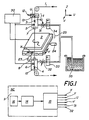
- a wire-electrode 1 passes continuously between two wire guides 3 and 4 placed on either side of the workpiece 2 to be machined, thanks to mechanisms (not shown) driving the wire while braking it so as to give it a predetermined mechanical tension.
- Two friction contacts 5 and 6 bring the machining current emitted by a pulse generator 30 to the electrode, while two injection nozzles 7 and 8 direct jets of machining liquid along the wire 1 and in the slot cut in room 2 by the latter.
- the upper wire guide 3, the nozzle 7, and the contact 5 are arranged in a machining head 10 movable along the vertical axis Z, and in general, also movable (in relatively small strokes) in a horizontal plane , along two orthogonal axes U and V, which allows to tilt the wire, the lower wire guide 4 remaining fixed.
- This movement (U, V) is achieved by means of a cross-motion table 11, actuated by a servo-mechanism (of known type, not shown) comprising the two motors 12 and 13.
- the lower machining head 15 containing the guide 4, the nozzle 8 and the lower contact 6 remains fixed relative to the frame of the machine.
- the workpiece 2 is fixed by means of a mechanism not shown on a table itself fixed to the bottom of a work tank (not shown) filled with machining liquid.
- the latter is movable along two horizontal and orthogonal axes X and Y thanks to a cross-motion table 25 actuated by a servo-mechanism (of known type, not shown) comprising the two motors 23 and 24.
- the cutting path is stored on an information carrier 16 which transmits its data to the computing unit 14 of a digital control 9.
- the latter also comprises a suitably programmed unit, at least one memory and a reader , as well as an installation 18 (processor or interpolator) controlling and controlling the relative displacements between the electrode part 2 and the wire electrode 1 by actuating the motors 12, 13, 23 and 24, and controlling other parameters of machining, such as the injection pressure of the machining liquid by acting on the solenoid valves 31 and 32.
- the computing unit 14 evaluates the cutting path and transmits control signals to the interpolator 18 for distributing the displacements in the two directions X and Y actuated by the two motors 23 and 24.
- the pulse generator 30 is connected between the two electrodes 1 and 2 so as to emit successive voltage pulses for initiating discharges in the machining area.
- a dielectric fluid reservoir feeds the work tank and the injection circuits to the nozzles 7 and 8 of the machining heads. These are shown schematically in Figure 1 by the pump 35 and the electro-valves 31 and 32 connected to the liquid distributors 33 and 34.
- the control of the machining regime is carried out as follows: the evolution of at least one factor (for example an integrated machining voltage supplied by a unit of the numerical control of the machine, or the rate of sparks without waiting) whose variation beyond a given threshold is the index of a degradation of the machining; as soon as this factor reaches this critical reference threshold, the value V of the parameter (s) to be modified, for example the frequency of the pulses emitted by the generator or the injection pressure, is varied by a first quantity Q given, this modification being for example a decrease; this variation can cause a variation of the factor (s) monitored as a result of a change in the machining conditions; as long as the value of this factor (s) remains above the critical threshold, we continue to decrease the parameter (s), in steps of quantities Q x data, until this parameter (s) are reduced to the expected value V (X), or until each factor has returned below the critical threshold (the parameter having reached only the value V (x)); note that when the modified parameter is a factor of the power of the
- the value of the parameter of a quantity Q ' is increased; this can cause a variation of the factor or factors monitored following a change in the machining conditions; as long as the value of this factor (s) remains below the critical threshold, the parameter (s), in steps, of quantities Q ' x given are continued; - when the parameter has the value V again, machining is continued with the starting speed.
- the quantities Q, Q x , Q ', Q' x may be equal or different for each of the decrements and increments (elementary variations) made. These quantities may be sufficiently small (and the bearings sufficiently numerous) for the variation to be gradual and practically continuous.
- the magnitude whose evolution beyond a certain limit triggers the protection strategy described above may be different from the factor or factors whose evolution serves to enslave the duration of the levels of variation.
- the object of the present invention is therefore a device. as defined in claim 1.
- This method makes it possible to decrease or increase a parameter in order to restore good machining conditions, that is to say machining without risk of rupture, then to do so, either increase or decrease in order to bring back to its original value, the danger having disappeared.
- the parameter that is varied to stop the degradation of the machining conditions is generally one of the factors of the machining rate, in particular the power of the pulses emitted by the generator, such as the frequency of these pulses. , the intensity of the machining current, the spark time or the spark voltage.
- the factor giving an image of the machining conditions is, for example, the average machining voltage, the servo voltage (difference between the average reference voltage and the average machining voltage), or the average duration of the machining. discharge initiation time, or spark rate without waiting.
- the quantities whose parameter (s) are varied at each step and the number of these steps, the final value V (X) reached by the parameter (s), or the threshold (s) ( s) critical (s) achieved by the servo factor (s) and indices of a certain state of degradation of the machining, or giving the signal for the implementation of the protection strategy have been, for example, predetermined experimentally by choosing values to avoid short circuits and breakage of the wire while changing the regime as little and as quickly as possible.
- These values can be stored for example on an appropriate element of the information carrier connected to the calculation unit of the numerical control of the EDM machine. They are for example a function of the material pair and / or the height of the part / material and / or geometry of the wire electrode.
- protection strategies described in the present invention can also be used to vary a parameter when machining requires a change in speed, for example when cutting along a curved path or in a piece of variable thickness.
- the invention will be illustrated below by some of the many possible embodiments, described solely by way of example, but not limited thereto.
- two factors indicating the state of the machining conditions are simultaneously monitored: - the average servo voltage Usai and - the spark rate without waiting TL. You can enable or disable the monitoring of any of these factors. They can also be replaced by another factor related to this average rate or voltage. For example, the first can be used to trigger the protection, the second to control the duration of the parameter variation steps.
- Usai value is obtained by integrating Usa on the train of successive measurements made during the preceding eighty milliseconds, thanks to the element 22 shown schematically in Figure 2.
- the rate TL is the number of sparks without waiting observed during a given time, or for a number of successive pulses, the generator 30 being set to a given pause time between two pulses.
- a recoil of the wire can occur when the wire opens into a small diameter hole, the liquid under pressure in the hole exiting through the slot by driving the wire. If no action is taken, the recoil increases and can cause a short circuit against a machined face, or even pull the wire out of the slot. This results in an increase in Usai such as Usai ⁇ Usa H. As soon as Usai reaches this threshold, a signal triggers the protection, that is to say commands a first decrease of f and p. These decreases have in particular the effect of reducing or even suppressing the arrow.
- the minimum regime is in progress (see example 2).
- the reaction consists in decreasing the frequency f and the injection pressure p. The reductions continue in stages as long as Usa ⁇ Usa B.
Landscapes
- Chemical & Material Sciences (AREA)
- Chemical Kinetics & Catalysis (AREA)
- Electrochemistry (AREA)
- Engineering & Computer Science (AREA)
- Mechanical Engineering (AREA)
- Electrical Discharge Machining, Electrochemical Machining, And Combined Machining (AREA)
Applications Claiming Priority (2)
| Application Number | Priority Date | Filing Date | Title |
|---|---|---|---|
| CH100/89 | 1989-01-13 | ||
| CH10089 | 1989-01-13 |
Publications (2)
| Publication Number | Publication Date |
|---|---|
| EP0383370A1 true EP0383370A1 (de) | 1990-08-22 |
| EP0383370B1 EP0383370B1 (de) | 1995-07-26 |
Family
ID=4179259
Family Applications (1)
| Application Number | Title | Priority Date | Filing Date |
|---|---|---|---|
| EP90200082A Expired - Lifetime EP0383370B1 (de) | 1989-01-13 | 1990-01-12 | Steuerungseinrichtung und Verfahren zum elektroerosiven Schneiden unter Vermeidung von Drahtbruch |
Country Status (7)
| Country | Link |
|---|---|
| US (1) | US5122630A (de) |
| EP (1) | EP0383370B1 (de) |
| JP (1) | JP2636453B2 (de) |
| KR (1) | KR930011212B1 (de) |
| DD (1) | DD298361A5 (de) |
| DE (1) | DE69021096T2 (de) |
| ES (1) | ES2078292T3 (de) |
Cited By (4)
| Publication number | Priority date | Publication date | Assignee | Title |
|---|---|---|---|---|
| EP0504861A1 (de) * | 1991-03-20 | 1992-09-23 | AG für industrielle Elektronik AGIE Losone bei Locarno | Verfahren zum Anschneiden eines Werkstücks beim funkenerosiven Schneiden |
| CN1781639A (zh) * | 2004-11-23 | 2006-06-07 | 通用电气公司 | 用于监控和控制电侵蚀的方法和系统 |
| EP2862660A3 (de) * | 2013-10-21 | 2015-05-27 | Fanuc Corporation | Drahterodiermaschine mit Mitteln zur Erkennung von Fluiddruck |
| FR3083999A1 (fr) * | 2018-07-23 | 2020-01-24 | Thermocompact | Procede et dispositif de prevention des ruptures de fil electrode lors d'un usinage par etincelage erosif |
Families Citing this family (11)
| Publication number | Priority date | Publication date | Assignee | Title |
|---|---|---|---|---|
| JPH05228736A (ja) * | 1992-02-25 | 1993-09-07 | Fanuc Ltd | ワイヤカット放電加工機の制御方法 |
| JP3237895B2 (ja) * | 1992-04-30 | 2001-12-10 | ブラザー工業株式会社 | ワイヤ放電加工機 |
| DE19547480C2 (de) * | 1995-12-19 | 2001-10-04 | Agie Sa | Verfahren und Vorrichtung zum Drahterodieren |
| DE19614200C2 (de) * | 1996-04-10 | 2000-03-02 | Agie Sa | Verfahren zum Bewegen wenigstens eines Führungskopfes einer Drahterosionsmaschine, sowie Drahterosionsmaschine mit einer Stelleinrichtung zum Durchführen von Bewegungen wenigstens eines Führungskopfes |
| DE19614128C2 (de) * | 1996-04-10 | 2001-03-01 | Agie Sa | Verfahren und Vorrichtung zur Steuerung einer Werkzeugmaschine, insbesondere einer Funkenerosionsmaschine |
| DE19950151A1 (de) * | 1999-10-18 | 2001-06-13 | Agie Sa | Prozeßparameteroptimierung beim funkerosiven Bearbeiten |
| WO2011145390A1 (ja) * | 2010-05-18 | 2011-11-24 | 三菱電機株式会社 | 被加工物保持具、ワイヤ放電加工装置、薄板製造方法、および半導体ウエハ製造方法 |
| JP5166586B1 (ja) * | 2011-10-13 | 2013-03-21 | ファナック株式会社 | 加工状態に基づき加工液量を調節するワイヤ放電加工機 |
| US10272510B2 (en) * | 2016-01-14 | 2019-04-30 | United Technologies Corporation | Electrical discharge machining apparatus |
| EP3932601A1 (de) * | 2020-07-03 | 2022-01-05 | Agie Charmilles SA | Regelungsverfahren für hochgeschwindigkeitsdrahtschneiden |
| CN120447351B (zh) * | 2025-07-11 | 2025-10-10 | 广东米尔迪克智能机械实业有限公司 | 一种电火花加工中的动态参数优化方法 |
Citations (1)
| Publication number | Priority date | Publication date | Assignee | Title |
|---|---|---|---|---|
| EP0276195A1 (de) * | 1987-01-13 | 1988-07-27 | Charmilles Technologies S.A. | Vorrichtung und Verfahren, um dem Bruch eines Metalldrahtes zuvorzukommen |
Family Cites Families (18)
| Publication number | Priority date | Publication date | Assignee | Title |
|---|---|---|---|---|
| US4005303A (en) * | 1972-03-07 | 1977-01-25 | Inoue-Japan Research Inc. | EDM parameter control system |
| US3973104A (en) * | 1972-08-17 | 1976-08-03 | A.G. Fur Industrielle Elektronik Agie Losone B. Locarno | Apparatus for regulating an electric discharge machining gap |
| CH581005A5 (de) * | 1974-11-14 | 1976-10-29 | Charmilles Sa Ateliers | |
| US4078163A (en) * | 1975-06-04 | 1978-03-07 | Bell Jr Oliver A | Programmable current control system for wire electrode electrical discharge machining apparatus |
| CH610796A5 (de) * | 1977-02-25 | 1979-05-15 | Charmilles Sa Ateliers | |
| JPS55137837A (en) * | 1979-04-03 | 1980-10-28 | Mitsubishi Electric Corp | Wire cut type electric discharge machining |
| CH630829A5 (fr) * | 1979-05-08 | 1982-07-15 | Charmilles Sa Ateliers | Procede pour usiner par etincelage erosif. |
| JPS5976718A (ja) * | 1982-10-25 | 1984-05-01 | Fanuc Ltd | ワイヤカツト放電加工条件設定方式 |
| JPS6029226A (ja) * | 1983-07-21 | 1985-02-14 | Fanuc Ltd | ワイヤカット放電加工装置 |
| JPH0783968B2 (ja) * | 1985-01-30 | 1995-09-13 | 株式会社アマダ | ワイヤカツト放電加工機の加工制御方法 |
| GB8521514D0 (en) * | 1985-08-29 | 1985-10-02 | Pratt Int Ltd Burnerd | Chucks |
| JPS6284919A (ja) * | 1985-10-08 | 1987-04-18 | Amada Co Ltd | 放電加工装置の加工状態検出方法及びその装置 |
| DE3622520A1 (de) * | 1986-07-04 | 1988-01-07 | Deckel Ag Friedrich | Verfahren und einrichtung zur ueberwachung eines funkenerodier-prozesses in einer funkenerodiermaschine |
| JPS6347569A (ja) * | 1986-08-13 | 1988-02-29 | Hitachi Ltd | 回転導入機 |
| JPH07108487B2 (ja) * | 1986-11-05 | 1995-11-22 | 三菱電機株式会社 | ワイヤカツト放電加工装置 |
| CH673798A5 (de) * | 1987-02-03 | 1990-04-12 | Charmilles Technologies | |
| JPS63318210A (ja) * | 1987-06-18 | 1988-12-27 | Mitsubishi Electric Corp | 放電加工機の制御装置 |
| JPH0622763B2 (ja) * | 1987-06-22 | 1994-03-30 | 三菱電機株式会社 | 放電加工装置 |
-
1990
- 1990-01-12 EP EP90200082A patent/EP0383370B1/de not_active Expired - Lifetime
- 1990-01-12 DE DE69021096T patent/DE69021096T2/de not_active Expired - Lifetime
- 1990-01-12 ES ES90200082T patent/ES2078292T3/es not_active Expired - Lifetime
- 1990-01-13 KR KR1019900000394A patent/KR930011212B1/ko not_active Expired - Fee Related
- 1990-01-15 DD DD90337113A patent/DD298361A5/de not_active IP Right Cessation
- 1990-01-16 US US07/465,304 patent/US5122630A/en not_active Expired - Lifetime
- 1990-01-16 JP JP2004648A patent/JP2636453B2/ja not_active Expired - Fee Related
Patent Citations (1)
| Publication number | Priority date | Publication date | Assignee | Title |
|---|---|---|---|---|
| EP0276195A1 (de) * | 1987-01-13 | 1988-07-27 | Charmilles Technologies S.A. | Vorrichtung und Verfahren, um dem Bruch eines Metalldrahtes zuvorzukommen |
Cited By (10)
| Publication number | Priority date | Publication date | Assignee | Title |
|---|---|---|---|---|
| EP0504861A1 (de) * | 1991-03-20 | 1992-09-23 | AG für industrielle Elektronik AGIE Losone bei Locarno | Verfahren zum Anschneiden eines Werkstücks beim funkenerosiven Schneiden |
| CN1781639A (zh) * | 2004-11-23 | 2006-06-07 | 通用电气公司 | 用于监控和控制电侵蚀的方法和系统 |
| EP1658915A3 (de) * | 2004-11-23 | 2012-03-07 | General Electric Company | Verfahren und System für Überwachung und Steuerung von Funkenerosionsbearbeitung |
| US8323473B2 (en) | 2004-11-23 | 2012-12-04 | General Electric Company | Methods and systems for monitoring and controlling electroerosion |
| CN1781639B (zh) * | 2004-11-23 | 2014-05-14 | 通用电气公司 | 用于监控和控制电侵蚀的方法和系统 |
| EP1658915B1 (de) | 2004-11-23 | 2019-03-06 | General Electric Company | Verfahren und System für Überwachung und Steuerung von Funkenerosionsbearbeitung |
| EP2862660A3 (de) * | 2013-10-21 | 2015-05-27 | Fanuc Corporation | Drahterodiermaschine mit Mitteln zur Erkennung von Fluiddruck |
| FR3083999A1 (fr) * | 2018-07-23 | 2020-01-24 | Thermocompact | Procede et dispositif de prevention des ruptures de fil electrode lors d'un usinage par etincelage erosif |
| EP3599044A1 (de) * | 2018-07-23 | 2020-01-29 | Thermocompact | Verfahren und vorrichtung zum verhindern des reissens des elektrodendrahts bei der bearbeitung mit funkenerosion |
| EP3599044B1 (de) * | 2018-07-23 | 2023-07-19 | Thermocompact | Verfahren und vorrichtung zum verhindern des reissens des elektrodendrahts bei der bearbeitung mit funkenerosion |
Also Published As
| Publication number | Publication date |
|---|---|
| EP0383370B1 (de) | 1995-07-26 |
| KR900011539A (ko) | 1990-08-01 |
| DE69021096T2 (de) | 1996-08-01 |
| KR930011212B1 (ko) | 1993-11-29 |
| ES2078292T3 (es) | 1995-12-16 |
| JP2636453B2 (ja) | 1997-07-30 |
| DD298361A5 (de) | 1992-02-20 |
| JPH02292129A (ja) | 1990-12-03 |
| DE69021096D1 (de) | 1995-08-31 |
| US5122630A (en) | 1992-06-16 |
Similar Documents
| Publication | Publication Date | Title |
|---|---|---|
| EP0383370B1 (de) | Steuerungseinrichtung und Verfahren zum elektroerosiven Schneiden unter Vermeidung von Drahtbruch | |
| EP2502700B1 (de) | Steuerverfahren einer Verspritzungsvorrichtung für eine Werkzeugmaschine | |
| EP0724528B1 (de) | Verfahren zur füllung eines behälters mit einem referenznettogewicht | |
| FR2516274A1 (fr) | Appareil et procede de controle de la vitesse d'un moteur et du debit d'un fluide | |
| FR2478512A1 (de) | ||
| EP0271439B1 (de) | Flüssigkeitszuführeinrichtung für Elektroerosionsbearbeitung | |
| EP0378278B1 (de) | Steuerungseinrichtung und Verfahren zum elektroerosiven Schneiden mittels einer Drahtelektrode | |
| EP0303240A1 (de) | Anlage und Verfahren, um in einem ununterbrochenen Versorgungskreis eine Bearbeitungsflüssigkeit zu filtern | |
| CH646894A5 (fr) | Procede et dispositif pour decouper par decharges erosives. | |
| FR2552786A1 (fr) | Dispositif regulateur pour la commande de rotation d'un dispositif de deroulement, en particulier d'une ensouple d'une machine a tisser | |
| FR2510449A1 (fr) | Procede et appareil d'usinage electrique a fil electrode circulant | |
| BE1006086A4 (fr) | Metier a jet fluide et methode pour assurer son fonctionnement. | |
| CH673798A5 (de) | ||
| EP0378280A1 (de) | Einrichtung und Verfahren zur Steuerung einer Parametersvariation beim elektroerosiven Drahtschneiden | |
| FR2499893A1 (fr) | Procede et appareil d'usinage par decharges electriques | |
| EP0166143B1 (de) | Verfahren zum Schneiden mittels Elektroerosion und Vorrichtung zum Durchführen dieses Verfahrens | |
| EP1063043B1 (de) | Verfahren und Vorrichtung zur Funkenerosionsbearbeitung | |
| CH654233A5 (en) | Method and device for cutting sharp corners in an electrode workpiece by erosive discharge | |
| FR2865424A1 (fr) | Procede et installation de coupage plasma a courant asservi au gaz plasmagene | |
| CH638125A5 (fr) | Procede et dispositif pour l'usinage par etincelage. | |
| EP0276195B1 (de) | Vorrichtung und Verfahren, um dem Bruch eines Metalldrahtes zuvorzukommen | |
| FR2814794A1 (fr) | Procede de gestion des gaz en coupage, soudage ou traitement thermique | |
| WO2023202985A1 (fr) | Unite d'entrainement en rotation d'un outil anime et procede de controle associe | |
| WO1979000120A1 (fr) | Procede d'usinage par electro-erosion et systeme pour sa mise en oeuvre | |
| EP0903196A1 (de) | Schweissdrahtversorgungsverfahren und -vorrichtung zum TIG-Schweissen |
Legal Events
| Date | Code | Title | Description |
|---|---|---|---|
| PUAI | Public reference made under article 153(3) epc to a published international application that has entered the european phase |
Free format text: ORIGINAL CODE: 0009012 |
|
| AK | Designated contracting states |
Kind code of ref document: A1 Designated state(s): DE ES FR GB IT SE |
|
| 17P | Request for examination filed |
Effective date: 19910301 |
|
| 17Q | First examination report despatched |
Effective date: 19920122 |
|
| GRAA | (expected) grant |
Free format text: ORIGINAL CODE: 0009210 |
|
| AK | Designated contracting states |
Kind code of ref document: B1 Designated state(s): DE ES FR GB IT SE |
|
| REF | Corresponds to: |
Ref document number: 69021096 Country of ref document: DE Date of ref document: 19950831 |
|
| ITF | It: translation for a ep patent filed | ||
| GBT | Gb: translation of ep patent filed (gb section 77(6)(a)/1977) |
Effective date: 19951103 |
|
| REG | Reference to a national code |
Ref country code: ES Ref legal event code: FG2A Ref document number: 2078292 Country of ref document: ES Kind code of ref document: T3 |
|
| PLBE | No opposition filed within time limit |
Free format text: ORIGINAL CODE: 0009261 |
|
| STAA | Information on the status of an ep patent application or granted ep patent |
Free format text: STATUS: NO OPPOSITION FILED WITHIN TIME LIMIT |
|
| 26N | No opposition filed | ||
| REG | Reference to a national code |
Ref country code: GB Ref legal event code: IF02 |
|
| PGFP | Annual fee paid to national office [announced via postgrant information from national office to epo] |
Ref country code: SE Payment date: 20030109 Year of fee payment: 14 |
|
| PG25 | Lapsed in a contracting state [announced via postgrant information from national office to epo] |
Ref country code: SE Free format text: LAPSE BECAUSE OF NON-PAYMENT OF DUE FEES Effective date: 20040113 |
|
| EUG | Se: european patent has lapsed | ||
| PGFP | Annual fee paid to national office [announced via postgrant information from national office to epo] |
Ref country code: ES Payment date: 20090122 Year of fee payment: 20 |
|
| PGFP | Annual fee paid to national office [announced via postgrant information from national office to epo] |
Ref country code: DE Payment date: 20090122 Year of fee payment: 20 |
|
| PGFP | Annual fee paid to national office [announced via postgrant information from national office to epo] |
Ref country code: GB Payment date: 20090122 Year of fee payment: 20 |
|
| PGFP | Annual fee paid to national office [announced via postgrant information from national office to epo] |
Ref country code: IT Payment date: 20090126 Year of fee payment: 20 |
|
| PGFP | Annual fee paid to national office [announced via postgrant information from national office to epo] |
Ref country code: FR Payment date: 20090115 Year of fee payment: 20 |
|
| REG | Reference to a national code |
Ref country code: GB Ref legal event code: PE20 Expiry date: 20100111 |
|
| REG | Reference to a national code |
Ref country code: ES Ref legal event code: FD2A Effective date: 20100113 |
|
| PG25 | Lapsed in a contracting state [announced via postgrant information from national office to epo] |
Ref country code: ES Free format text: LAPSE BECAUSE OF EXPIRATION OF PROTECTION Effective date: 20100113 |
|
| PG25 | Lapsed in a contracting state [announced via postgrant information from national office to epo] |
Ref country code: GB Free format text: LAPSE BECAUSE OF EXPIRATION OF PROTECTION Effective date: 20100111 |
|
| PG25 | Lapsed in a contracting state [announced via postgrant information from national office to epo] |
Ref country code: DE Free format text: LAPSE BECAUSE OF EXPIRATION OF PROTECTION Effective date: 20100112 |