EP0383511A2 - Traversée hermétique pour fibres optiques - Google Patents
Traversée hermétique pour fibres optiques Download PDFInfo
- Publication number
- EP0383511A2 EP0383511A2 EP90301449A EP90301449A EP0383511A2 EP 0383511 A2 EP0383511 A2 EP 0383511A2 EP 90301449 A EP90301449 A EP 90301449A EP 90301449 A EP90301449 A EP 90301449A EP 0383511 A2 EP0383511 A2 EP 0383511A2
- Authority
- EP
- European Patent Office
- Prior art keywords
- gland
- passageway
- tube
- gas
- fibres
- Prior art date
- Legal status (The legal status is an assumption and is not a legal conclusion. Google has not performed a legal analysis and makes no representation as to the accuracy of the status listed.)
- Granted
Links
- 210000004907 gland Anatomy 0.000 title claims abstract description 65
- 230000003287 optical effect Effects 0.000 title claims description 8
- 239000013307 optical fiber Substances 0.000 claims abstract description 11
- 230000000903 blocking effect Effects 0.000 claims description 29
- 239000000835 fiber Substances 0.000 claims description 19
- 239000000463 material Substances 0.000 claims description 17
- 239000007788 liquid Substances 0.000 claims description 8
- 238000000576 coating method Methods 0.000 claims description 7
- 239000011248 coating agent Substances 0.000 claims description 6
- 239000004519 grease Substances 0.000 claims description 5
- 235000015110 jellies Nutrition 0.000 claims description 5
- 239000008274 jelly Substances 0.000 claims description 5
- 239000011344 liquid material Substances 0.000 claims description 4
- 239000000853 adhesive Substances 0.000 claims description 3
- 230000001070 adhesive effect Effects 0.000 claims description 3
- 239000004020 conductor Substances 0.000 claims description 3
- 238000002347 injection Methods 0.000 claims description 2
- 239000007924 injection Substances 0.000 claims description 2
- 239000011253 protective coating Substances 0.000 claims description 2
- 238000012546 transfer Methods 0.000 claims description 2
- 230000008602 contraction Effects 0.000 claims 1
- 239000003822 epoxy resin Substances 0.000 claims 1
- 229920000647 polyepoxide Polymers 0.000 claims 1
- XLYOFNOQVPJJNP-UHFFFAOYSA-N water Substances O XLYOFNOQVPJJNP-UHFFFAOYSA-N 0.000 abstract description 7
- 238000010276 construction Methods 0.000 abstract 1
- 239000007789 gas Substances 0.000 description 31
- 239000011347 resin Substances 0.000 description 10
- 229920005989 resin Polymers 0.000 description 10
- RYGMFSIKBFXOCR-UHFFFAOYSA-N Copper Chemical compound [Cu] RYGMFSIKBFXOCR-UHFFFAOYSA-N 0.000 description 6
- 229910052802 copper Inorganic materials 0.000 description 6
- 239000010949 copper Substances 0.000 description 6
- 238000013461 design Methods 0.000 description 6
- SZUVGFMDDVSKSI-WIFOCOSTSA-N (1s,2s,3s,5r)-1-(carboxymethyl)-3,5-bis[(4-phenoxyphenyl)methyl-propylcarbamoyl]cyclopentane-1,2-dicarboxylic acid Chemical compound O=C([C@@H]1[C@@H]([C@](CC(O)=O)([C@H](C(=O)N(CCC)CC=2C=CC(OC=3C=CC=CC=3)=CC=2)C1)C(O)=O)C(O)=O)N(CCC)CC(C=C1)=CC=C1OC1=CC=CC=C1 SZUVGFMDDVSKSI-WIFOCOSTSA-N 0.000 description 5
- 229940126543 compound 14 Drugs 0.000 description 5
- 229910000679 solder Inorganic materials 0.000 description 5
- NIXOWILDQLNWCW-UHFFFAOYSA-M Acrylate Chemical compound [O-]C(=O)C=C NIXOWILDQLNWCW-UHFFFAOYSA-M 0.000 description 4
- 150000001875 compounds Chemical class 0.000 description 4
- 239000002184 metal Substances 0.000 description 4
- 229910052751 metal Inorganic materials 0.000 description 4
- 239000004593 Epoxy Substances 0.000 description 3
- 239000004033 plastic Substances 0.000 description 3
- 229920003023 plastic Polymers 0.000 description 3
- 230000008901 benefit Effects 0.000 description 2
- 239000000919 ceramic Substances 0.000 description 2
- 239000000945 filler Substances 0.000 description 2
- 239000012530 fluid Substances 0.000 description 2
- 239000013535 sea water Substances 0.000 description 2
- 238000007789 sealing Methods 0.000 description 2
- 239000007787 solid Substances 0.000 description 2
- 239000010935 stainless steel Substances 0.000 description 2
- 230000035882 stress Effects 0.000 description 2
- 238000012360 testing method Methods 0.000 description 2
- 229910000497 Amalgam Inorganic materials 0.000 description 1
- 229910000881 Cu alloy Inorganic materials 0.000 description 1
- UFHFLCQGNIYNRP-UHFFFAOYSA-N Hydrogen Chemical compound [H][H] UFHFLCQGNIYNRP-UHFFFAOYSA-N 0.000 description 1
- 230000015556 catabolic process Effects 0.000 description 1
- 239000004568 cement Substances 0.000 description 1
- 230000006835 compression Effects 0.000 description 1
- 238000007906 compression Methods 0.000 description 1
- 230000000694 effects Effects 0.000 description 1
- 238000005516 engineering process Methods 0.000 description 1
- 238000007667 floating Methods 0.000 description 1
- 239000001307 helium Substances 0.000 description 1
- 229910052734 helium Inorganic materials 0.000 description 1
- SWQJXJOGLNCZEY-UHFFFAOYSA-N helium atom Chemical compound [He] SWQJXJOGLNCZEY-UHFFFAOYSA-N 0.000 description 1
- 239000001257 hydrogen Substances 0.000 description 1
- 229910052739 hydrogen Inorganic materials 0.000 description 1
- 230000002706 hydrostatic effect Effects 0.000 description 1
- 229910000833 kovar Inorganic materials 0.000 description 1
- 230000007774 longterm Effects 0.000 description 1
- 238000004519 manufacturing process Methods 0.000 description 1
- 230000007246 mechanism Effects 0.000 description 1
- 239000012528 membrane Substances 0.000 description 1
- 238000000034 method Methods 0.000 description 1
- 230000004048 modification Effects 0.000 description 1
- 238000012986 modification Methods 0.000 description 1
- 230000036961 partial effect Effects 0.000 description 1
- 230000035699 permeability Effects 0.000 description 1
- 239000004810 polytetrafluoroethylene Substances 0.000 description 1
- 229920001343 polytetrafluoroethylene Polymers 0.000 description 1
- 229910001220 stainless steel Inorganic materials 0.000 description 1
- 229910001256 stainless steel alloy Inorganic materials 0.000 description 1
- 230000008646 thermal stress Effects 0.000 description 1
- 230000036962 time dependent Effects 0.000 description 1
Images

Classifications
-
- G—PHYSICS
- G02—OPTICS
- G02B—OPTICAL ELEMENTS, SYSTEMS OR APPARATUS
- G02B6/00—Light guides; Structural details of arrangements comprising light guides and other optical elements, e.g. couplings
- G02B6/44—Mechanical structures for providing tensile strength and external protection for fibres, e.g. optical transmission cables
- G02B6/4401—Optical cables
- G02B6/4415—Cables for special applications
- G02B6/4427—Pressure resistant cables, e.g. undersea cables
- G02B6/4428—Penetrator systems in pressure-resistant devices
-
- G—PHYSICS
- G02—OPTICS
- G02B—OPTICAL ELEMENTS, SYSTEMS OR APPARATUS
- G02B6/00—Light guides; Structural details of arrangements comprising light guides and other optical elements, e.g. couplings
- G02B6/24—Coupling light guides
- G02B6/42—Coupling light guides with opto-electronic elements
- G02B6/4201—Packages, e.g. shape, construction, internal or external details
- G02B6/4248—Feed-through connections for the hermetical passage of fibres through a package wall
Definitions
- This invention relates to an hermetic high-pressure-resistant gland for optical fibres and has particular but not exclusive application for submerged repeaters for a submarine telecommunications link.
- a liquid filler 13 is filled to ensure that if a pressure is applied it is exerted uniformly around the solder. It is claimed that with such an arrangement it is possible to obtain an optical hermetic fixture structure which inhibits the leakage thereinto of sea water and water vapour by virtue of the self-sealing effect which results from the compression of the solder by the liquid filler, even if sea water pressure is applied to the feed-through in case of a cable fault.
- an hermetic gland for optical fibres comprising a rigid gas-tight member having a passageway from a high pressure end of the gland extending therethrough to a low pressure end of the gland, at least one optical fibre extending into the passageway at the high pressure end and emerging from the passageway at the low pressure end, a gas-blocking grease jelly or similarly viscous liquid material filling said passageway over such length as to provide the required gas blocking property in the passageway of the gland, and a plug in the passageway at the low pressure end whose purpose is to prevent leakage of said gas blocking material from the passageway and to provide the required hydraulic pressure-resisting property within said passageway of the gland.
- a submersible repeater for an underwater optical fibre telecommunication system comprising a pressure-resistant housing, a primary pressure-resistant cable entry gland for an optical fibre submarine cable and a secondary optical fibre gas blocking gland, said gas blocking gland comprising a passageway through which the fibres extend and which has a length substantially greater than its width, said passageway containing a gas blocking grease jelly or similarly viscous liquid material over such a length in the passageway as to act as the gas block for the secondary gland.
- the gas blocking function is achieved by using a low permeability, high viscosity liquid that is maintained in intimate contact with the coated fibre and internal surfaces of the gland body, irrespective of changes in temperature.
- the separate pressure resisting function becomes a less critical item in terms of leakage performance. Instead of having to seal against the small helium gas molecule the block has only to prevent the leakage of the high viscosity fluid.
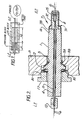
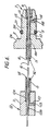
- the gland comprises an electrically insulating body 1 preferably of ceramic having an annular shoulder 2 and an annular recess 3 both to enable the body to be removably secured in a bulkhead B in a submerged repeater as shown more clearly in Figure 4 of the drawing.
- the recess 3 accommodates an O-ring 3A preferably of rubber and a gasket 3B preferably of copper is squeezed between the stepped co-operating faces 2A of the shoulder 2 and 2B of the bulkhead B.
- the ceramic body 1 has a bore 4 which accommodates a metallic tube 5 (not shown in Figure 4), in this embodiment of stainless steel or copper alloy, and the tube 5 is a loose or sliding fit in the bore 4.
- the tube 5 is designed as a pressure resisting tube able to withstand the hydrostatic pressure prevailing in deep oceans.
- the fibres are loose individual fibres and may for example be acrylate coated fibres.
- the high pressure fitting comprises a tubular metallic ring 7A made of Kovar (Registered Trade Mark) which has a larger diameter portion 7B soldered to an end 1A of the body 1 and a smaller diameter portion 7C soldered to a tube 8, made of copper in this embodiment.
- Kovar Registered Trade Mark
- the high-pressure end fitting copper tube 8 is held co-axial with the bore 4 of the body 1 by means of the tubular ring 7A and an end portion 5A of the tube 5 fits into a corresponding recess 8A of the tube 8.
- the fibre portions 6A are sealed in the high pressure gland by a plug 9 formed by a resin end-fill which is locked into the high pressure-end fitting 8 by means of internal castellated annular corrugations 9A.
- the other end, the low pressure (LP) end, of the gland comprises a metal (copper) low pressure end fitting 12 which has a larger internal bore 12A and a smaller bore 12B, an end portion 5B of the tube 5 being located within the bore 12A and held therein by means of a resin end-fill 13 which fills the larger bore 12A and the smaller bore 12B and locks the end portion 5B of the copper tube 5 into the bore 12A of the end fitting 12.
- a metal (copper) low pressure end fitting 12 which has a larger internal bore 12A and a smaller bore 12B, an end portion 5B of the tube 5 being located within the bore 12A and held therein by means of a resin end-fill 13 which fills the larger bore 12A and the smaller bore 12B and locks the end portion 5B of the copper tube 5 into the bore 12A of the end fitting 12.
- the space between the fibres 6 and the internal passageway or bore 5C of the tube 5 is filled with a viscous gas blocking material 14.
- the main purpose of the material 14 is to restrict the permeation of gas by maintaining intimate contact between the tube 5 and the fibres 6 irrespective of temperature variations causing differential thermal expansion between tube and fibres.
- a gas blocking compound sold under the trade name HYVIS is used, although there maybe other suitable gas blocking grease, jelly or similarly viscous liquid gas blocking materials.
- the method of assembly is as follows: with fibres 6 in the tube the plug 9 is formed and cured at the HP end by a resin end-fill which is prevented from entering the inner chamber 10 by means of the washer 11 made in this embodiment of PTFE.
- the gas blocking material 14 is then injected through the port 8B at the HP end to completely fill the tube 5.
- High-viscosity compound may be heated to facilitate filling.
- a simple rubber or plastic sleeve 15 is fitted to seal the filling port 8B.
- the LP end fitting 12 is then screwed (a portion of bore 12A is screw threaded) to the threaded LP end of 5B of the tube 5 and a second epoxy plug 13 is formed, again by injection through a port 12C, to completely fill the cavity 12A, 12B and hence seal the compound 14 within the tube 5.
- the LP epoxy plug 13 which prevents leakage of the gas-blocking compound under pressure.
- the purpose of the rubber sleeve 15 is to retain the compound 14 and provide a flexible membrane to allow for thermal expansion of the compound 14.
- the sole function of the epoxy plug 9 at the HP end is to provide a block at the fibre entry position to ensure that the injected compound 14 can only fill the tube 5.
- the assembled gland body is then inserted into the bulkhead B as shown in Figure 4.
- a disc spring 16 is interposed between the shoulder 2 and a nut 17 which is screwed into a threaded bore B1 to drive the co-operating faces 2A, 2B towards each other and clamp the gasket 3B. Rubber O-ring seal 3A slides over the surface of the inner bore B2 of the bulkhead and seals to it.
- tube 5 being electrically connected with an electrically-conductive high-pressure end fitting 8 and an electrically-conductive-low pressure end fitting 12 provides an electrical connection and enables e.g. power transfer to be made through the gland via the copper tube. Therefore where the repeater is powered from the cable the power can be transmitted via the tube in use of the gland.
- the gland described is not designed as a primary water block where the tube 5 is being used as an electrical conductor and is intended for use as a secondary water block behind a primary water block such as the one described in the aforementioned patent 2058484.
- the gland is not required to provide an electrical path for e.g. power feed, then it would not be necessary for the body 1 to be electrically insulating.
- the body 1 need not overlap very far the end portion of the tube 5 to which it is fitted.
- An embodiment providing no power feed through is illustrated in Figure 5.
- the gland is similar in all respects to the gland of Figures 1 to 4 except as follows.
- the body 21 of metal e.g. copper or stainless steel has the shoulder 2 but extends no further. Otherwise like reference numerals in Figure 5 refer to like parts as in Figures 1 and 4.
- the high pressure end ring 7A is no longer required.
- the gasket 3B will be used but is not shown.
- the tube 8 is now not a separate part but an integral portion of body 1 and is so not referenced.
- the other spring component 16 and nut 17 are also not shown but would of course be required for securing the gland through a bulkhead.
- the acrylate-coated fibres have a diameter of 0.25mm although with overcoating fibre of e.g. 0.65mm could be contemplated.
- the bore 5c of the tube 5 has a length substantially greater than its width and would normally be at least an order of magnitude greater.
- the length of the passageway 5c is about 10cms and the diameter about 5mm which is between one and two orders of magnitude greater.
- the embodiments described (including Fig 7) have a designed leakage rate of not more than 1 x 10 ⁇ 9 parts in 25 years of life at an ocean depth pressure of 83 Mega Pascals. Up to twelve fibres are envisaged gas blocked through a single gland.
- a big advantage is the use of acrylate-coated fibres which are not stripped for use in the gland.
- Other coatings could however be used and the acrylate coating can be overcoated with a further plastics coating if desired, provided a gas-blocking coating is maintained.
- the embodiments described are filled with the gas blocking material from one end, ie. the HP end before the hydraulic pressure resisting plug 13 at the LP end is formed, which means that the plug 13 is not independently testable to ensure its integrity.
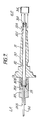
- the embodiment of Fig 7 provides for independent testing of the plug before completion of the gland with gas blocking material.
- a gland body 30 has a bore 31.
- a tube 32 fits concentrically into the body 30 so there is an annular space 33 between the outer surface of the tube 32 and the bore 31 of the body, except at the right hand end as viewed in Fig 7 where the end portion 32A of tube 32 is an interference fit in a reduce diameter portion 31A of bore 31.
- the optical fibre 34 extends through the tube 32.
- a cap 35 is screwed onto a threaded end portion 30A of body 30 and an O ring is compressed against the end face 30B of body 30 and also seals against the fibre 34. Then resin is injected through port 35A until resin appears from the end 35B of cap 35, and the resin cured at room temperature. This forms the hydraulic pressure resisting plug of the gland and this can be tested with gas pressure from the high pressure end.
- a small length of heat shrink tubing (not shown) is applied over each end of the gland and the protruding fibre to provide a bend limiting device and a liquid seal for the gas blocking material.
- a metal sleeve 36 is applied over the port 30C to prevent leakage.
- This design is intended in this embodiment for a single fibre and the length of the gas block is about 25mm and the length of the resin block about 10mm.
- the hydraulic pressure resisting plug comprises an adhesive material which is bonded both to the coating of the or each fibre and to the wall of the passageway through which the fibres extend, and the integrity of the bond needs to be such as to prevent leakage of the gas blocking material but does not need to provide a gas blocking function. In general therefore the plug will always have a shorter length in the passageway than the gas blocking material in the passageway.
Landscapes
- Physics & Mathematics (AREA)
- General Physics & Mathematics (AREA)
- Optics & Photonics (AREA)
- Mechanical Coupling Of Light Guides (AREA)
- Cable Accessories (AREA)
- Light Guides In General And Applications Therefor (AREA)
Applications Claiming Priority (2)
| Application Number | Priority Date | Filing Date | Title |
|---|---|---|---|
| GB8903560 | 1989-02-16 | ||
| GB8903560A GB2228340B (en) | 1989-02-16 | 1989-02-16 | Hermetic gland for optical fibres |
Publications (3)
| Publication Number | Publication Date |
|---|---|
| EP0383511A2 true EP0383511A2 (fr) | 1990-08-22 |
| EP0383511A3 EP0383511A3 (fr) | 1992-03-11 |
| EP0383511B1 EP0383511B1 (fr) | 1995-09-13 |
Family
ID=10651812
Family Applications (1)
| Application Number | Title | Priority Date | Filing Date |
|---|---|---|---|
| EP90301449A Expired - Lifetime EP0383511B1 (fr) | 1989-02-16 | 1990-02-12 | Traversée hermétique pour fibres optiques |
Country Status (6)
| Country | Link |
|---|---|
| US (1) | US5024503A (fr) |
| EP (1) | EP0383511B1 (fr) |
| JP (1) | JP3054639B2 (fr) |
| AU (1) | AU619652B2 (fr) |
| DE (1) | DE69022261T2 (fr) |
| GB (1) | GB2228340B (fr) |
Cited By (7)
| Publication number | Priority date | Publication date | Assignee | Title |
|---|---|---|---|---|
| EP0469853A3 (en) * | 1990-07-31 | 1992-05-06 | Canon Kabushiki Kaisha | Light guide |
| GB2310050A (en) * | 1996-01-23 | 1997-08-13 | Mark Edward Pleydell | Hermetic seal for an optic fibre |
| WO2002025344A1 (fr) * | 2000-09-25 | 2002-03-28 | Schlumberger Technology B.V. | Traversee optique |
| WO2006085066A1 (fr) * | 2005-02-10 | 2006-08-17 | Brand-Rex Limited | Couplage de tube scelle pour des tubes de fibre optique |
| EP1703308A1 (fr) * | 2005-03-16 | 2006-09-20 | Institut Français du Pétrole | Dispositif de traversée étanche pour fibre optique |
| DE19734274B4 (de) * | 1997-08-07 | 2010-04-08 | Norddeutsche Seekabelwerke Gmbh & Co. Kg | Kommunikationsnetz mit Lichtwellenleitern zwischen Teilnehmern und Kommunikationzentralen in bestehenden Versorgungsleitungen |
| EP2339385A1 (fr) * | 2009-12-22 | 2011-06-29 | JDS Uniphase Corporation | Joint hermétique entre un emballage et une fibre optique |
Families Citing this family (16)
| Publication number | Priority date | Publication date | Assignee | Title |
|---|---|---|---|---|
| US5253315A (en) * | 1990-12-24 | 1993-10-12 | Fentress Vernon A | Method and apparatus for installing a fiber optic cable by capture of a coupling nut or coupling nut assembly |
| EP0523473B1 (fr) * | 1991-07-05 | 1996-12-04 | Nippon Steel Welding Products & Engineering Co., Ltd. | Système de connexion avec un câble de fibres optiques revetu d'un tube métallique |
| US5159651A (en) * | 1991-11-25 | 1992-10-27 | The Rochester Corporation | Electro-optical connector assembly |
| US6321021B1 (en) * | 1999-07-12 | 2001-11-20 | Ocean Design, Inc. | End seal assembly for tubular conduit |
| US6294766B1 (en) * | 1999-07-31 | 2001-09-25 | Microsemi Corporation | Battery cell bypass with pre-loaded compression action |
| US6836609B2 (en) | 2001-01-25 | 2004-12-28 | Tyco Telecommunications (Us) Inc. | Gas blocking device for optical fiber repeater |
| JP4183991B2 (ja) * | 2002-07-12 | 2008-11-19 | シーシーエス株式会社 | 光ファイバ保持装置、光ファイバ保持方法 |
| JP2004296673A (ja) * | 2003-03-26 | 2004-10-21 | Tdk Corp | 水密プレート及びそれを備えた電源装置 |
| WO2006097972A1 (fr) * | 2005-03-11 | 2006-09-21 | Fujitsu Limited | Traversee de dispositif repeteur sous-marin et dispositif repeteur sous-marin |
| US8422835B2 (en) * | 2005-06-30 | 2013-04-16 | Weatherford/Lamb, Inc. | Optical waveguide feedthrough assembly |
| CA2548828C (fr) * | 2005-06-30 | 2016-09-13 | Weatherford/Lamb, Inc. | Ensemble de passage de guide d'ondes optiques |
| US7447390B2 (en) * | 2005-06-30 | 2008-11-04 | Weatherford/Lamb, Inc. | Pressure transducer with optical waveguide feedthrough assembly |
| US7751677B2 (en) * | 2005-06-30 | 2010-07-06 | Weatherford/Lamb, Inc. | Optical fiber feedthrough using axial seals for bi-directional sealing |
| CA2608800C (fr) * | 2006-11-01 | 2016-01-05 | Weatherford/Lamb, Inc. | Ensemble de traversee a guide d'onde optique |
| FR2963685A1 (fr) * | 2010-08-06 | 2012-02-10 | Carrier Kheops Bac | Passage d'un ruban de fibres optiques |
| US10606006B2 (en) * | 2016-09-20 | 2020-03-31 | Clearfield, Inc. | Optical fiber distribution systems and components |
Family Cites Families (16)
| Publication number | Priority date | Publication date | Assignee | Title |
|---|---|---|---|---|
| US3825320A (en) * | 1973-03-02 | 1974-07-23 | Us Navy | High-pressure optical bulkhead penetrator |
| GB1454600A (en) * | 1974-11-08 | 1976-11-03 | Plessey Co Ltd | Optical fibre connector doll' |
| JPS5916244B2 (ja) * | 1978-05-09 | 1984-04-14 | ケイディディ株式会社 | 光海底中継器の光ファイバ導入装置 |
| JPS5922203B2 (ja) * | 1978-10-06 | 1984-05-25 | ケイディディ株式会社 | 光海底中継器のフイ−ドスル |
| GB2043943B (en) * | 1979-02-27 | 1982-12-08 | Plessey Co Ltd | Optical cable gland |
| JPS6011321B2 (ja) * | 1981-01-20 | 1985-03-25 | ケイディディ株式会社 | 光海底中継器の光フアイバ接続部収容構造 |
| CA1217369A (fr) * | 1981-06-18 | 1987-02-03 | Peter Harvey | Systemes aeriens de transport d'electricite |
| JPS5897015A (ja) * | 1981-12-05 | 1983-06-09 | Kokusai Denshin Denwa Co Ltd <Kdd> | 水密型光フアイバコネクタ |
| FR2519149B1 (fr) * | 1981-12-30 | 1985-07-26 | Cables De Lyon Geoffroy Delore | Dispositif de jonction des extremites de deux cables sous-marins a fibres optiques et son procede de fabrication |
| JPS59176706A (ja) * | 1983-03-28 | 1984-10-06 | Kokusai Denshin Denwa Co Ltd <Kdd> | 光海底中継器用フイ−ドスルの光フアイバ気密固定構造 |
| GB2152297B (en) * | 1984-01-19 | 1988-10-19 | Stc Plc | Optical repeaters |
| IT1176347B (it) * | 1984-06-29 | 1987-08-18 | Pirelli Cavi Spa | Giunto per cavi sottomarini di telecomunicazione a fibre ottiche |
| IT1176522B (it) * | 1984-08-01 | 1987-08-18 | Pirelli Cavi Spa | Linea sottomarina per telecomunicazioni a fibre ottiche |
| US4759601A (en) * | 1985-06-24 | 1988-07-26 | Schlumberger Technology Corporation | Fiber optic connector assembly |
| US4834479A (en) * | 1986-12-11 | 1989-05-30 | American Telephone And Telegraph Company | High and low pressure fluidblock assembly |
| US4891640A (en) * | 1988-11-03 | 1990-01-02 | Halliburton Logging Services, Inc. | High temperature and pressure fiber optic feedthrough for borehole usage |
-
1989
- 1989-02-16 GB GB8903560A patent/GB2228340B/en not_active Expired - Fee Related
-
1990
- 1990-02-12 DE DE69022261T patent/DE69022261T2/de not_active Expired - Fee Related
- 1990-02-12 EP EP90301449A patent/EP0383511B1/fr not_active Expired - Lifetime
- 1990-02-13 US US07/479,119 patent/US5024503A/en not_active Expired - Lifetime
- 1990-02-15 AU AU49836/90A patent/AU619652B2/en not_active Ceased
- 1990-02-16 JP JP2036002A patent/JP3054639B2/ja not_active Expired - Fee Related
Cited By (15)
| Publication number | Priority date | Publication date | Assignee | Title |
|---|---|---|---|---|
| EP0469853A3 (en) * | 1990-07-31 | 1992-05-06 | Canon Kabushiki Kaisha | Light guide |
| US5151967A (en) * | 1990-07-31 | 1992-09-29 | Canon Kabushiki Kaisha | Optical fiber sealing assembly |
| GB2310050A (en) * | 1996-01-23 | 1997-08-13 | Mark Edward Pleydell | Hermetic seal for an optic fibre |
| GB2310050B (en) * | 1996-01-23 | 1998-01-14 | Mark Edward Pleydell | Fibre optic sealing method |
| DE19734274B4 (de) * | 1997-08-07 | 2010-04-08 | Norddeutsche Seekabelwerke Gmbh & Co. Kg | Kommunikationsnetz mit Lichtwellenleitern zwischen Teilnehmern und Kommunikationzentralen in bestehenden Versorgungsleitungen |
| GB2383139A (en) * | 2000-09-25 | 2003-06-18 | Schlumberger Holdings | An optical feedthrough |
| FR2814550A1 (fr) * | 2000-09-25 | 2002-03-29 | Schlumberger Services Petrol | Traversee optique |
| GB2383139B (en) * | 2000-09-25 | 2004-06-02 | Schlumberger Holdings | Feedthrough with optic fibre sealed in protective tube |
| WO2002025344A1 (fr) * | 2000-09-25 | 2002-03-28 | Schlumberger Technology B.V. | Traversee optique |
| WO2006085066A1 (fr) * | 2005-02-10 | 2006-08-17 | Brand-Rex Limited | Couplage de tube scelle pour des tubes de fibre optique |
| EP1703308A1 (fr) * | 2005-03-16 | 2006-09-20 | Institut Français du Pétrole | Dispositif de traversée étanche pour fibre optique |
| FR2883385A1 (fr) * | 2005-03-16 | 2006-09-22 | Inst Francais Du Petrole | Dispositif de traversee etanche pour fibre optique |
| US7400811B2 (en) | 2005-03-16 | 2008-07-15 | Institut Francais Du Petrole | Sealed feedthrough assembly for optical fiber |
| EP2339385A1 (fr) * | 2009-12-22 | 2011-06-29 | JDS Uniphase Corporation | Joint hermétique entre un emballage et une fibre optique |
| US8342756B2 (en) | 2009-12-22 | 2013-01-01 | Jds Uniphase Corporation | Hermetic seal between a package and an optical fiber |
Also Published As
| Publication number | Publication date |
|---|---|
| JPH03197902A (ja) | 1991-08-29 |
| JP3054639B2 (ja) | 2000-06-19 |
| GB8903560D0 (en) | 1989-04-05 |
| AU4983690A (en) | 1990-08-23 |
| EP0383511B1 (fr) | 1995-09-13 |
| EP0383511A3 (fr) | 1992-03-11 |
| DE69022261T2 (de) | 1996-02-15 |
| GB2228340B (en) | 1993-02-10 |
| DE69022261D1 (de) | 1995-10-19 |
| GB2228340A (en) | 1990-08-22 |
| AU619652B2 (en) | 1992-01-30 |
| US5024503A (en) | 1991-06-18 |
Similar Documents
| Publication | Publication Date | Title |
|---|---|---|
| US5024503A (en) | Hermetic gland for optical fibres | |
| US4891640A (en) | High temperature and pressure fiber optic feedthrough for borehole usage | |
| US4172212A (en) | Submarine housing for submarine cable system repeater components or the like | |
| US4329540A (en) | Blocking feed-through for coaxial cable | |
| US4653846A (en) | Optical fiber hermetic fixing structure of feedthrough for optical submarine repeater | |
| US4679875A (en) | Attachment of electric cable to submergible pump motor heads | |
| US4296996A (en) | Feedthrough for optical fiber | |
| US6364677B1 (en) | Arrangement in terminating a cable | |
| US6443780B2 (en) | Conductor assembly for pothead connector | |
| US2838596A (en) | Glands for entry of submarine cables into repeater housings | |
| BRPI0808788A2 (pt) | Conector elétrico, método de provisão de uma conexão elétrica para um componente submersível disposto no interior de um poço, e sistema. | |
| US4678270A (en) | Submersible optical repeaters and optical fibre glands | |
| US4214809A (en) | Fiber optic penetrator | |
| US10297990B2 (en) | Subsea splice termination unit | |
| US5301959A (en) | Sealing gland | |
| JP4364276B2 (ja) | 海底中継装置のフィードスルー及び海底中継装置 | |
| US4038490A (en) | Water-seal splice for coaxial cables and method of making same | |
| EP2390698B1 (fr) | Dispositif de connexion d'isolation opto-électronique étanche et cabine étanche | |
| SU1513551A1 (ru) | Кабельный подводный соединитель | |
| JPS6235081B2 (fr) | ||
| JPS62212609A (ja) | レンズコネクタ型フイ−ドスル | |
| JPS62238505A (ja) | レンズコネクタ型フイ−ドスル | |
| CN121498821A (zh) | 一种小直径投入式深井液位密封结构及方法 | |
| EP3246739A1 (fr) | Appareil de terminaison de connecteur optique sans époxy pour une utilisation à haute température et haute pression |
Legal Events
| Date | Code | Title | Description |
|---|---|---|---|
| PUAI | Public reference made under article 153(3) epc to a published international application that has entered the european phase |
Free format text: ORIGINAL CODE: 0009012 |
|
| AK | Designated contracting states |
Kind code of ref document: A2 Designated state(s): BE DE ES FR GR IT NL |
|
| PUAL | Search report despatched |
Free format text: ORIGINAL CODE: 0009013 |
|
| AK | Designated contracting states |
Kind code of ref document: A3 Designated state(s): BE DE ES FR GR IT NL |
|
| 17P | Request for examination filed |
Effective date: 19920413 |
|
| 17Q | First examination report despatched |
Effective date: 19931115 |
|
| RAP1 | Party data changed (applicant data changed or rights of an application transferred) |
Owner name: NORTHERN TELECOM LIMITED |
|
| GRAA | (expected) grant |
Free format text: ORIGINAL CODE: 0009210 |
|
| AK | Designated contracting states |
Kind code of ref document: B1 Designated state(s): BE DE ES FR GR IT NL |
|
| PG25 | Lapsed in a contracting state [announced via postgrant information from national office to epo] |
Ref country code: IT Free format text: LAPSE BECAUSE OF FAILURE TO SUBMIT A TRANSLATION OF THE DESCRIPTION OR TO PAY THE FEE WITHIN THE PRE;WARNING: LAPSES OF ITALIAN PATENTS WITH EFFECTIVE DATE BEFORE 2007 MAY HAVE OCCURRED AT ANY TIME BEFORE 2007. THE CORRECT EFFECTIVE DATE MAY BE DIFFERENT FROM THE ONE RECORDED.SCRIBED TIME-LIMIT Effective date: 19950913 Ref country code: BE Effective date: 19950913 Ref country code: GR Free format text: LAPSE BECAUSE OF FAILURE TO SUBMIT A TRANSLATION OF THE DESCRIPTION OR TO PAY THE FEE WITHIN THE PRESCRIBED TIME-LIMIT Effective date: 19950913 Ref country code: ES Free format text: THE PATENT HAS BEEN ANNULLED BY A DECISION OF A NATIONAL AUTHORITY Effective date: 19950913 Ref country code: NL Free format text: LAPSE BECAUSE OF FAILURE TO SUBMIT A TRANSLATION OF THE DESCRIPTION OR TO PAY THE FEE WITHIN THE PRESCRIBED TIME-LIMIT Effective date: 19950913 |
|
| ET | Fr: translation filed | ||
| REF | Corresponds to: |
Ref document number: 69022261 Country of ref document: DE Date of ref document: 19951019 |
|
| NLV1 | Nl: lapsed or annulled due to failure to fulfill the requirements of art. 29p and 29m of the patents act | ||
| PLBE | No opposition filed within time limit |
Free format text: ORIGINAL CODE: 0009261 |
|
| STAA | Information on the status of an ep patent application or granted ep patent |
Free format text: STATUS: NO OPPOSITION FILED WITHIN TIME LIMIT |
|
| 26N | No opposition filed | ||
| PGFP | Annual fee paid to national office [announced via postgrant information from national office to epo] |
Ref country code: FR Payment date: 20040202 Year of fee payment: 15 |
|
| PGFP | Annual fee paid to national office [announced via postgrant information from national office to epo] |
Ref country code: DE Payment date: 20040227 Year of fee payment: 15 |
|
| REG | Reference to a national code |
Ref country code: FR Ref legal event code: CD |
|
| PG25 | Lapsed in a contracting state [announced via postgrant information from national office to epo] |
Ref country code: DE Free format text: LAPSE BECAUSE OF NON-PAYMENT OF DUE FEES Effective date: 20050901 |
|
| PG25 | Lapsed in a contracting state [announced via postgrant information from national office to epo] |
Ref country code: FR Free format text: LAPSE BECAUSE OF NON-PAYMENT OF DUE FEES Effective date: 20051031 |
|
| REG | Reference to a national code |
Ref country code: FR Ref legal event code: ST Effective date: 20051031 |