EP0383535A2 - Appareil pour l'amélioration du son stéréophonique - Google Patents
Appareil pour l'amélioration du son stéréophonique Download PDFInfo
- Publication number
- EP0383535A2 EP0383535A2 EP90301499A EP90301499A EP0383535A2 EP 0383535 A2 EP0383535 A2 EP 0383535A2 EP 90301499 A EP90301499 A EP 90301499A EP 90301499 A EP90301499 A EP 90301499A EP 0383535 A2 EP0383535 A2 EP 0383535A2
- Authority
- EP
- European Patent Office
- Prior art keywords
- stereophonic
- speakers
- loudspeakers
- internal
- external
- Prior art date
- Legal status (The legal status is an assumption and is not a legal conclusion. Google has not performed a legal analysis and makes no representation as to the accuracy of the status listed.)
- Granted
Links
Images

Classifications
-
- H—ELECTRICITY
- H04—ELECTRIC COMMUNICATION TECHNIQUE
- H04N—PICTORIAL COMMUNICATION, e.g. TELEVISION
- H04N5/00—Details of television systems
- H04N5/44—Receiver circuitry for the reception of television signals according to analogue transmission standards
- H04N5/60—Receiver circuitry for the reception of television signals according to analogue transmission standards for the sound signals
- H04N5/607—Receiver circuitry for the reception of television signals according to analogue transmission standards for the sound signals for more than one sound signal, e.g. stereo, multilanguages
-
- H—ELECTRICITY
- H04—ELECTRIC COMMUNICATION TECHNIQUE
- H04R—LOUDSPEAKERS, MICROPHONES, GRAMOPHONE PICK-UPS OR LIKE ACOUSTIC ELECTROMECHANICAL TRANSDUCERS; ELECTRIC HEARING AIDS; PUBLIC ADDRESS SYSTEMS
- H04R5/00—Stereophonic arrangements
- H04R5/02—Spatial or constructional arrangements of loudspeakers
-
- H—ELECTRICITY
- H04—ELECTRIC COMMUNICATION TECHNIQUE
- H04S—STEREOPHONIC SYSTEMS
- H04S1/00—Two-channel systems
- H04S1/002—Non-adaptive circuits, e.g. manually adjustable or static, for enhancing the sound image or the spatial distribution
Definitions
- the present invention relates to improving stereophonic sound produced by televison sets, and more particularly, to improving the quality and directionality of the sound produced by internal loudspeakers of said television sets.
- the perceived directionality of the stereophonic sound provided by speakers aimed from the sides of a television set is greatly reduced since the sound is aimed away from the viewer towards the reflecting walls of the room. Even if the speakers are aimed from the front of a "table top" television set, the loudspeakers may be of relatively poor quality for several reasons. First, the quality of the speakers used on the table model television sets usually have limited bass response and power capability. Second, the stereophonic directionality of such table top model speakers is minimal since the spacing between the loudspeakers is limited by the size of the cabinet which often is inadequate for providing an adequate spatial stereophonic perception.
- the present invention provides apparatus for improving the stereophonic sound from a source, such as a "table top” or “portable” television set or other source providing stereophonic sound, having at least two loudspeakers disposed within the cabinet of the source with the signal fed to the internal loudspeakers being externally accessible through a jack or the like. It is intended that at least two other loudspeakers be provided external to the source and that the external loudspeakers desirably be disposed in a spaced apart relationship greater than the spaced apart relationship of the internal loudspeakers with said external speakers facing in the direction of the listener.
- the stereophonic channels are fed to the external loudspeakers while a mixture of the stereophonic channels, i.e., a difference signal of the stereophonic channels, is fed to each of the internal loudspeakers at a power level less than the power fed to each of the external speakers.
- a mixture of the stereophonic channels i.e., a difference signal of the stereophonic channels
- the internal speakers of a television set having stereophonic sound capability are mounted at the diametrically opposed sides of the cabinet radiating their acoustic sound responses in opposite directions orthogonal to the direction of the viewer who usually is generally positioned in front of the display device, e.g., a CRT.
- the stereophonic spatial perception of the left side sound which should appear to come from the left side, and the right side sound which should appear to come from the right side is reduced in effect. This situation is common for a number of reasons.
- the stereo sound is not directionality aimed in the direction of the viewer or listener, as the case may be.
- the listener hears reflections and reflections of reflections with substantial mixing of the left and right side sounds being received by each ear. Additionally, these reflections are spread over a large wall area making the perceived direction of a particular sound very indefinite. Moreover, whatever directionality there is changes with the position of the listener.
- the distance between the speakers, even if the speakers were disposed in front of the cabinet and aimed at the viewer, is limited to the dimensions of the cabinet which typically is insufficient for an adequate stereophonic effect.
- the loudspeakers provided with "table top” or “portable” televisions sets may not be of the highest quality.
- this sound improvement can be further enhanced by using the loudspeakers internal to the television set in conjunction with the external speakers.
- the internal speakers are used to provide a mixture or blend of the stereophonic output, e.g., a difference signal of the stereophonic channels, and thus provide a spatial quality of sound simulating a reflected ambience which creates a more effective "wall of sound" rather than the point sources of sound provided by the spaced apart external speakers alone.
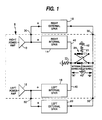
- Figure 1 a block diagram schematic of an apparatus for enhancing the stereophonic sound available from a television set, or any other source or device for producing stereophonic sound.
- the stereophonic device shown in Figure 1 and generally designated 8 has a right channel power amplifier 10 for amplifying a right side signal and feeding the amplified result to a right internal loudspeaker 14 providing a right side sound to the listener.
- a left channel power amplifier 12 provides an amplified left side signal to a left internal speaker 16. Both speakers 4 and 16 are disposed in spaced apart relationship within a cabinet 24 (See Fig. 2) and are hard wired to their respective power amplifiers 10 and 12.
- Power amplifiers 10 and 12 can be any amplifier, operational amplifier, or integrated circuit amplifier common in the art.
- external right and left speakers 18 and 20 are connected in parallel with the respective internal speakers without disconnecting the internal speakers 14 and 16.
- a switch 23 selectably inserts resistors 21 and 22 in parallel-series with the common ground side of the internal speakers 14 and 16, and resistor 21 in series with the common ground side of external loudspeakers 18 and 20, as will be described below.
- external speakers 18 and 20 are intended to be separately housed in their own cabinet structures and spaced as widely apart as possible. To achieve the maximum beneficial effect, external speakers 18 and 20 should have a spaced apart relationship larger than the spaced apart relationship of internal speakers 14 and 16. In the alternative, external speakers 16 and 18 can also be housed within a stand or cart 26 as shown in Figure 2.
- FIG. 2 there is shown a representation of a cabinet 24 of a television set having internal stereophonic speakers 14 and 16 with external speakers 18 and 20 mounted within a stand 26.
- Internal loudspeakers 14 and 16 are aimed at right angles to the viewer.
- Stand 26 is designed to receive and support television set cabinet 24 on a raised platform 44 in a predetermined directional orientation with loudspeakers 18 and 20 being aimed towards the viewer in the same general direction as CRT screen 28.
- the internal speakers 14 and 16 can be disposed facing frontward in which case it is preferred that external speakers 18 and 20 be disposed in a greater spaced apart relationship than the internal speakers 14 and 16. In either case, it is desirable that speakers 18 and 20 have greater frequency response and lower distortion than internal speakers 14 and 16.
- speakers 18 and 20 when housed in a fully enclosed and baffled box within stand 26 typically would have improved bass response, and can have a larger magnet structure than speakers 14 and 16 for lower distortion and improved efficiency.
- the external loud speakers 18 and 20 are coupled to their respective power amplifiers 10 and 12 and internal ground 42 through external connect terminals or "jacks" 30 and 32 respectively.
- Switch 23 is disposed within cabinet 24, and is controllable by the listener.
- a first mode designated “internal” is chosen by moving switch 23 into the left position shown by arrow "A”. In this mode, it is intended that no external speakers are connected by the listener to terminals 30 and 32 and the full power of each channel is provided to the respective internal speakers 14 and 16 with a low side common lead 40 being directly connected to internal ground 42.
- a second mode is chosen by moving switch 23 into the left position shown by arrow "A" as in the first mode discussed hereinabove.
- the external speakers 18 and 20 are intended to be connected to respective terminals 30 and 32.
- the full power of each channel is provided to the respective internal speakers 14 and 16, with low side common lead 40 of speakers 14 and 16 being directly connected to internal ground 42 as in the "internal” mode.
- external speakers 18 and 20 are coupled to internal ground 42 through resistor 21.
- resistor 21 is 33 ohms when speakers 18 and 20 have a nominal eight ohms impedance. Naturally, resistor 21 should have a sufficient power rating as required.
- a third mode designated “enhanced external”, is chosen by moving switch 23 into the right position shown by arrow "B".
- this mode it is intended that external speakers 18 and 20 are connected to terminals 30 and 32, respectively and spaced apart by a distance greater than the distance between internal speakers 14 and 16 and aimed toward the listener.
- the external speakers 18 and 20 are driven at full power, but the internal speakers 14 and 16 are driven at a lower power with accentuated difference components.
- This "enhanced external” mode greatly improves the spatial quality of the sound by adding "reflected ambience". It has been found that the "reflected ambience" creates more of a "wall of sound” rather than the point sources of sound emanating only from the external speakers 18 and 20 as would normally be the case.
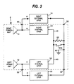
- Fig. 3 The equivalent circuit or simpler version of the structure for the "enhanced external" mode is shown in Fig. 3 with switch 23 being shown as a single pole single throw switch designated as 23a, connected across equivalent resistor 22′ representing the value of resistor 22 of Fig. 1 (of exemplary value 39 ohms)as parallelled by resistor 21.
- resistor 22′ of Fig. 3 is short circuited.
- switch 23a is opened for removing the short circuit across resistor 22′, thus placing resistor 22′ in series with the common terminals 40 of internal speakers 14 and 16.
- the value of resistor 22′ is selected for effectuating the desirable attenuation and in the exemplary embodiment is an 18 ohm resistor of appropriate power capability, when speakers 14 and 16 are 8 ohms each. In such a configuration, loudspeakers 14 and 16 will be primarily driven by a difference signal substantially equal to the difference between the right and left signals divided by two.
- the right internal speaker 14 will have a signal therethrough of .59R-.41L and left speaker 16 will have a signal therethrough of .59L-.41R.
- These values for the signals through the respective internal speakers 14 and 16 are easily derived by those skilled in the art considering the voltage division between the two internal speakers 14 and 16 and the 18 ohm equivalent value of resistor 22′, and considering that the output impedances of power amplifiers 10 and 12 are much lower than 8 ohms.
- the relationship of the left and right difference components can be changed by changing the resistance value of resistor 22.
- the internal speakers 14 and 16 are provided with an attenuated difference signal which has been found to be an appropriate signal for an ambience "fill in" sound.
Landscapes
- Engineering & Computer Science (AREA)
- Signal Processing (AREA)
- Physics & Mathematics (AREA)
- Acoustics & Sound (AREA)
- Multimedia (AREA)
- Stereophonic System (AREA)
- Stereo-Broadcasting Methods (AREA)
- Circuit For Audible Band Transducer (AREA)
- Headphones And Earphones (AREA)
- Nitrogen Condensed Heterocyclic Rings (AREA)
- Saccharide Compounds (AREA)
- Organic Low-Molecular-Weight Compounds And Preparation Thereof (AREA)
Applications Claiming Priority (2)
| Application Number | Priority Date | Filing Date | Title |
|---|---|---|---|
| US07/310,102 US5005201A (en) | 1989-02-14 | 1989-02-14 | Apparatus and method thereof for improvement of stereophonic sound |
| US310102 | 2002-12-04 |
Publications (3)
| Publication Number | Publication Date |
|---|---|
| EP0383535A2 true EP0383535A2 (fr) | 1990-08-22 |
| EP0383535A3 EP0383535A3 (fr) | 1991-09-11 |
| EP0383535B1 EP0383535B1 (fr) | 1994-12-28 |
Family
ID=23200998
Family Applications (1)
| Application Number | Title | Priority Date | Filing Date |
|---|---|---|---|
| EP90301499A Expired - Lifetime EP0383535B1 (fr) | 1989-02-14 | 1990-02-13 | Appareil pour l'amélioration du son stéréophonique |
Country Status (10)
| Country | Link |
|---|---|
| US (1) | US5005201A (fr) |
| EP (1) | EP0383535B1 (fr) |
| JP (1) | JPH02261299A (fr) |
| KR (1) | KR900013784A (fr) |
| CN (1) | CN1024312C (fr) |
| AT (1) | ATE116499T1 (fr) |
| DE (1) | DE69015380D1 (fr) |
| FI (1) | FI900703A7 (fr) |
| PT (1) | PT93132A (fr) |
| TR (1) | TR26269A (fr) |
Cited By (4)
| Publication number | Priority date | Publication date | Assignee | Title |
|---|---|---|---|---|
| EP0584719A1 (fr) * | 1992-08-28 | 1994-03-02 | Thomson Consumer Electronics, Inc. | Circuit de commande pour expanseur spatial stéréo |
| EP0769874A1 (fr) * | 1995-10-19 | 1997-04-23 | NOKIA TECHNOLOGY GmbH | Assemblage amplificateur audio pour plus de deux canaux de reproduction |
| WO2008023167A1 (fr) * | 2006-08-25 | 2008-02-28 | Airsound Llp | Appareil de reproduction de son stéréo |
| CN101536541B (zh) * | 2006-08-25 | 2012-08-08 | 空气之声公司 | 用于再现立体声的设备 |
Families Citing this family (20)
| Publication number | Priority date | Publication date | Assignee | Title |
|---|---|---|---|---|
| US5181247A (en) * | 1990-07-23 | 1993-01-19 | Bose Corporation | Sound image enhancing |
| US5228085A (en) * | 1991-04-11 | 1993-07-13 | Bose Corporation | Perceived sound |
| JPH06197293A (ja) * | 1992-12-25 | 1994-07-15 | Toshiba Corp | テレビジョンセットのスピーカシステム |
| US5278361A (en) * | 1993-02-05 | 1994-01-11 | Thomson Consumer Electronics, Inc. | Loudspeaker system |
| DE69431356T2 (de) * | 1993-06-23 | 2003-04-17 | Apple Computer, Inc. | Computermonitor mit integriertem stereolautsprecher-richtmikrofon, und verfahren zur herstellung |
| US5828768A (en) * | 1994-05-11 | 1998-10-27 | Noise Cancellation Technologies, Inc. | Multimedia personal computer with active noise reduction and piezo speakers |
| WO1998053641A1 (fr) * | 1997-05-21 | 1998-11-26 | Oplinger Terry R | Systemes de haut-parleurs multicanaux integres dans une configuration de meuble de rangement du type support pour television |
| CN1647573B (zh) * | 2002-03-15 | 2010-06-16 | 夏普株式会社 | 图像显示装置 |
| JP3957281B2 (ja) * | 2002-07-09 | 2007-08-15 | パイオニア株式会社 | スピーカを備えた置き台 |
| JPWO2007052625A1 (ja) * | 2005-10-31 | 2009-04-30 | パナソニック株式会社 | 映像音声視聴システム |
| US7804972B2 (en) * | 2006-05-12 | 2010-09-28 | Cirrus Logic, Inc. | Method and apparatus for calibrating a sound beam-forming system |
| US7676049B2 (en) * | 2006-05-12 | 2010-03-09 | Cirrus Logic, Inc. | Reconfigurable audio-video surround sound receiver (AVR) and method |
| WO2007127822A2 (fr) * | 2006-04-28 | 2007-11-08 | Cirrus Logic, Inc. | Récepteur de sons surround audio-vidéo reconfigurable (avr) et procédé |
| WO2007127757A2 (fr) * | 2006-04-28 | 2007-11-08 | Cirrus Logic, Inc. | Procédé et système de conformation de faisceaux sonores surround exploitant la partie de chevauchement des plages de fréquences des circuits d'attaque |
| US7606380B2 (en) * | 2006-04-28 | 2009-10-20 | Cirrus Logic, Inc. | Method and system for sound beam-forming using internal device speakers in conjunction with external speakers |
| US7606377B2 (en) * | 2006-05-12 | 2009-10-20 | Cirrus Logic, Inc. | Method and system for surround sound beam-forming using vertically displaced drivers |
| JP2008132161A (ja) * | 2006-11-28 | 2008-06-12 | Sony Corp | 収納ラック |
| JP5113471B2 (ja) * | 2007-10-02 | 2013-01-09 | S′Next株式会社 | スピーカシステム |
| CA3032479C (fr) * | 2012-04-26 | 2023-02-21 | Sonos,Inc. | Appariement de canaux multiples dans un systeme multimedia |
| JP2014072870A (ja) * | 2012-10-01 | 2014-04-21 | Funai Electric Co Ltd | テレビジョン装置 |
Family Cites Families (17)
| Publication number | Priority date | Publication date | Assignee | Title |
|---|---|---|---|---|
| GB894900A (en) * | 1957-03-13 | 1962-04-26 | Rola Celestion Ltd | Improvements in or relating to electronic apparatus incorporating electrostatic loudspeakers |
| US3417203A (en) * | 1965-04-13 | 1968-12-17 | Dynaco Inc | Two-channel stereo system with derived center channel |
| US3934092A (en) * | 1971-09-21 | 1976-01-20 | General Electric Company | Four channel stereophonic broadcasting system |
| US3933219A (en) * | 1974-04-08 | 1976-01-20 | Ambient, Inc. | Speaker system |
| US4002835A (en) * | 1975-06-06 | 1977-01-11 | Bumber Roger L | Multi-channel decoding circuit for two-channel audio systems |
| BR7704013A (pt) * | 1977-06-21 | 1978-02-14 | Ceramica Cordeiro Sa | Revestimento com dupla face para pisos e paredes |
| US4257067A (en) * | 1979-07-27 | 1981-03-17 | Christopher James S | Sound enhancement system for television receivers |
| US4355203A (en) * | 1980-03-12 | 1982-10-19 | Cohen Joel M | Stereo image separation and perimeter enhancement |
| US4308423A (en) * | 1980-03-12 | 1981-12-29 | Cohen Joel M | Stereo image separation and perimeter enhancement |
| DE3168990D1 (en) * | 1980-03-19 | 1985-03-28 | Matsushita Electric Industrial Co Ltd | Sound reproducing system having sonic image localization networks |
| US4410761A (en) * | 1980-11-05 | 1983-10-18 | Willi Schickedanz | Stereo loudspeaker system for a picture reproducing screen |
| DE3125348C2 (de) * | 1981-06-27 | 1986-09-04 | Interessengemeinschaft für Rundfunkschutzrechte GmbH Schutzrechtsverwertung & Co KG, 4000 Düsseldorf | Fernseh-Empfänger zur Wiedergabe von Sendungen mit Stereoton |
| DE3405128A1 (de) * | 1984-02-14 | 1985-08-22 | Standard Elektrik Lorenz Ag, 7000 Stuttgart | Vorrichtung zur stereophonen tonwiedergabe in einem fernsehempfangsgeraet |
| JPS613600A (ja) * | 1984-06-15 | 1986-01-09 | Pioneer Electronic Corp | 映像再生装置のステレオスピ−カ装置 |
| US4704728A (en) * | 1984-12-31 | 1987-11-03 | Peter Scheiber | Signal re-distribution, decoding and processing in accordance with amplitude, phase, and other characteristics |
| IT8634001V0 (it) * | 1986-01-10 | 1986-01-10 | Seleco Spa | Casse acustiche divaricabili per apparecchi riproduttori del suono. |
| JPS6416200A (en) * | 1987-07-10 | 1989-01-19 | Sanyo Electric Co | Sound field reproducing device |
-
1989
- 1989-02-14 US US07/310,102 patent/US5005201A/en not_active Expired - Fee Related
-
1990
- 1990-02-12 KR KR1019900001662A patent/KR900013784A/ko not_active Withdrawn
- 1990-02-13 FI FI900703A patent/FI900703A7/fi not_active Application Discontinuation
- 1990-02-13 TR TR90/0184A patent/TR26269A/xx unknown
- 1990-02-13 PT PT93132A patent/PT93132A/pt not_active Application Discontinuation
- 1990-02-13 DE DE69015380T patent/DE69015380D1/de not_active Expired - Lifetime
- 1990-02-13 CN CN90100742A patent/CN1024312C/zh not_active Expired - Fee Related
- 1990-02-13 AT AT90301499T patent/ATE116499T1/de active
- 1990-02-13 EP EP90301499A patent/EP0383535B1/fr not_active Expired - Lifetime
- 1990-02-14 JP JP2035057A patent/JPH02261299A/ja active Pending
Cited By (6)
| Publication number | Priority date | Publication date | Assignee | Title |
|---|---|---|---|---|
| EP0584719A1 (fr) * | 1992-08-28 | 1994-03-02 | Thomson Consumer Electronics, Inc. | Circuit de commande pour expanseur spatial stéréo |
| US5987141A (en) * | 1992-08-28 | 1999-11-16 | Thomson Consumer Electronics, Inc. | Stereo expander |
| EP0769874A1 (fr) * | 1995-10-19 | 1997-04-23 | NOKIA TECHNOLOGY GmbH | Assemblage amplificateur audio pour plus de deux canaux de reproduction |
| WO2008023167A1 (fr) * | 2006-08-25 | 2008-02-28 | Airsound Llp | Appareil de reproduction de son stéréo |
| CN101536541B (zh) * | 2006-08-25 | 2012-08-08 | 空气之声公司 | 用于再现立体声的设备 |
| US8553914B2 (en) | 2006-08-25 | 2013-10-08 | Airsound Llp | Apparatus for reproduction of stereo sound |
Also Published As
| Publication number | Publication date |
|---|---|
| CN1045010A (zh) | 1990-08-29 |
| EP0383535A3 (fr) | 1991-09-11 |
| JPH02261299A (ja) | 1990-10-24 |
| FI900703A0 (fi) | 1990-02-13 |
| EP0383535B1 (fr) | 1994-12-28 |
| ATE116499T1 (de) | 1995-01-15 |
| PT93132A (pt) | 1990-08-31 |
| FI900703A7 (fi) | 1990-08-15 |
| KR900013784A (ko) | 1990-09-06 |
| US5005201A (en) | 1991-04-02 |
| CN1024312C (zh) | 1994-04-20 |
| DE69015380D1 (de) | 1995-02-09 |
| TR26269A (tr) | 1995-02-15 |
Similar Documents
| Publication | Publication Date | Title |
|---|---|---|
| EP0383535B1 (fr) | Appareil pour l'amélioration du son stéréophonique | |
| JP2870754B2 (ja) | ステレオ電気音響変換装置 | |
| US8073176B2 (en) | Speakerbar | |
| US5301237A (en) | Surround sound loudspeakers | |
| US8363865B1 (en) | Multiple channel sound system using multi-speaker arrays | |
| US6219426B1 (en) | Center point stereo field expander for amplified musical instruments | |
| US5129006A (en) | Electronic audio signal amplifier and loudspeaker system | |
| US5212732A (en) | Effects speaker system | |
| CN102668596B (zh) | 用于对产生环绕声音的多通道音频信号进行处理的方法和音频系统 | |
| US5181247A (en) | Sound image enhancing | |
| WO1999048327A9 (fr) | Systeme de reproduction sonore peripherique pour theatre domestique | |
| US10327086B2 (en) | Head related transfer function equalization and transducer aiming of stereo dimensional array (SDA) loudspeakers | |
| JPH06105257A (ja) | テレビジョン受像機用スピーカ | |
| US7817812B2 (en) | Compact audio reproduction system with large perceived acoustic size and image | |
| EP0833545A2 (fr) | Dispositif de haut-parleur | |
| EP0370619A2 (fr) | Système de son à plusieurs haut-parleurs pour un dispositif d'affichage vidéo | |
| US7088827B1 (en) | Reconfigurable speaker system | |
| US5943431A (en) | Loudspeaker with tapered slot coupler and sound reproduction system | |
| US7164770B2 (en) | Surround sound speaker system | |
| US5257318A (en) | Earphone spacer with electronically variable sound level | |
| US4021614A (en) | Woofer equalizer | |
| JPS613600A (ja) | 映像再生装置のステレオスピ−カ装置 | |
| WO1990007252A1 (fr) | Systeme stereophonique | |
| MXPA00009111A (en) | In-home theater surround sound speaker system | |
| KR20060132425A (ko) | 슬림형 스피커 |
Legal Events
| Date | Code | Title | Description |
|---|---|---|---|
| PUAI | Public reference made under article 153(3) epc to a published international application that has entered the european phase |
Free format text: ORIGINAL CODE: 0009012 |
|
| AK | Designated contracting states |
Kind code of ref document: A2 Designated state(s): AT DE ES FR GB IT |
|
| PUAL | Search report despatched |
Free format text: ORIGINAL CODE: 0009013 |
|
| AK | Designated contracting states |
Kind code of ref document: A3 Designated state(s): AT DE ES FR GB IT |
|
| 17P | Request for examination filed |
Effective date: 19920224 |
|
| 17Q | First examination report despatched |
Effective date: 19940222 |
|
| GRAA | (expected) grant |
Free format text: ORIGINAL CODE: 0009210 |
|
| AK | Designated contracting states |
Kind code of ref document: B1 Designated state(s): AT DE ES FR GB IT |
|
| PG25 | Lapsed in a contracting state [announced via postgrant information from national office to epo] |
Ref country code: IT Free format text: LAPSE BECAUSE OF FAILURE TO SUBMIT A TRANSLATION OF THE DESCRIPTION OR TO PAY THE FEE WITHIN THE PRE;WARNING: LAPSES OF ITALIAN PATENTS WITH EFFECTIVE DATE BEFORE 2007 MAY HAVE OCCURRED AT ANY TIME BEFORE 2007. THE CORRECT EFFECTIVE DATE MAY BE DIFFERENT FROM THE ONE RECORDED.SCRIBED TIME-LIMIT Effective date: 19941228 Ref country code: ES Free format text: THE PATENT HAS BEEN ANNULLED BY A DECISION OF A NATIONAL AUTHORITY Effective date: 19941228 Ref country code: AT Effective date: 19941228 Ref country code: FR Effective date: 19941228 |
|
| REF | Corresponds to: |
Ref document number: 116499 Country of ref document: AT Date of ref document: 19950115 Kind code of ref document: T |
|
| REF | Corresponds to: |
Ref document number: 69015380 Country of ref document: DE Date of ref document: 19950209 |
|
| PG25 | Lapsed in a contracting state [announced via postgrant information from national office to epo] |
Ref country code: GB Effective date: 19950328 |
|
| PG25 | Lapsed in a contracting state [announced via postgrant information from national office to epo] |
Ref country code: DE Effective date: 19950329 |
|
| EN | Fr: translation not filed | ||
| PLBE | No opposition filed within time limit |
Free format text: ORIGINAL CODE: 0009261 |
|
| STAA | Information on the status of an ep patent application or granted ep patent |
Free format text: STATUS: NO OPPOSITION FILED WITHIN TIME LIMIT |
|
| GBPC | Gb: european patent ceased through non-payment of renewal fee |
Effective date: 19950328 |
|
| 26N | No opposition filed |