EP0383735A2 - Dispositif de serrage d'outil - Google Patents
Dispositif de serrage d'outil Download PDFInfo
- Publication number
- EP0383735A2 EP0383735A2 EP90850031A EP90850031A EP0383735A2 EP 0383735 A2 EP0383735 A2 EP 0383735A2 EP 90850031 A EP90850031 A EP 90850031A EP 90850031 A EP90850031 A EP 90850031A EP 0383735 A2 EP0383735 A2 EP 0383735A2
- Authority
- EP
- European Patent Office
- Prior art keywords
- clamping device
- locking ring
- draw
- abutment
- draw tap
- Prior art date
- Legal status (The legal status is an assumption and is not a legal conclusion. Google has not performed a legal analysis and makes no representation as to the accuracy of the status listed.)
- Granted
Links
- 230000007704 transition Effects 0.000 claims description 8
- 239000002184 metal Substances 0.000 claims description 3
- 238000006073 displacement reaction Methods 0.000 description 6
- 239000000463 material Substances 0.000 description 4
- 230000005540 biological transmission Effects 0.000 description 1
- 230000006835 compression Effects 0.000 description 1
- 238000007906 compression Methods 0.000 description 1
- 238000010276 construction Methods 0.000 description 1
- 238000012423 maintenance Methods 0.000 description 1
- 230000000284 resting effect Effects 0.000 description 1
- 239000004636 vulcanized rubber Substances 0.000 description 1
Images

Classifications
-
- B—PERFORMING OPERATIONS; TRANSPORTING
- B23—MACHINE TOOLS; METAL-WORKING NOT OTHERWISE PROVIDED FOR
- B23B—TURNING; BORING
- B23B31/00—Chucks; Expansion mandrels; Adaptations thereof for remote control
- B23B31/02—Chucks
- B23B31/24—Chucks characterised by features relating primarily to remote control of the gripping means
- B23B31/26—Chucks characterised by features relating primarily to remote control of the gripping means using mechanical transmission through the working-spindle
- B23B31/261—Chucks characterised by features relating primarily to remote control of the gripping means using mechanical transmission through the working-spindle clamping the end of the toolholder shank
-
- Y—GENERAL TAGGING OF NEW TECHNOLOGICAL DEVELOPMENTS; GENERAL TAGGING OF CROSS-SECTIONAL TECHNOLOGIES SPANNING OVER SEVERAL SECTIONS OF THE IPC; TECHNICAL SUBJECTS COVERED BY FORMER USPC CROSS-REFERENCE ART COLLECTIONS [XRACs] AND DIGESTS
- Y10—TECHNICAL SUBJECTS COVERED BY FORMER USPC
- Y10S—TECHNICAL SUBJECTS COVERED BY FORMER USPC CROSS-REFERENCE ART COLLECTIONS [XRACs] AND DIGESTS
- Y10S279/00—Chucks or sockets
- Y10S279/904—Quick change socket
-
- Y—GENERAL TAGGING OF NEW TECHNOLOGICAL DEVELOPMENTS; GENERAL TAGGING OF CROSS-SECTIONAL TECHNOLOGIES SPANNING OVER SEVERAL SECTIONS OF THE IPC; TECHNICAL SUBJECTS COVERED BY FORMER USPC CROSS-REFERENCE ART COLLECTIONS [XRACs] AND DIGESTS
- Y10—TECHNICAL SUBJECTS COVERED BY FORMER USPC
- Y10T—TECHNICAL SUBJECTS COVERED BY FORMER US CLASSIFICATION
- Y10T279/00—Chucks or sockets
- Y10T279/17—Socket type
- Y10T279/17411—Spring biased jaws
- Y10T279/17471—Resilient member reinforced by another resilient member
-
- Y—GENERAL TAGGING OF NEW TECHNOLOGICAL DEVELOPMENTS; GENERAL TAGGING OF CROSS-SECTIONAL TECHNOLOGIES SPANNING OVER SEVERAL SECTIONS OF THE IPC; TECHNICAL SUBJECTS COVERED BY FORMER USPC CROSS-REFERENCE ART COLLECTIONS [XRACs] AND DIGESTS
- Y10—TECHNICAL SUBJECTS COVERED BY FORMER USPC
- Y10T—TECHNICAL SUBJECTS COVERED BY FORMER US CLASSIFICATION
- Y10T279/00—Chucks or sockets
- Y10T279/17—Socket type
- Y10T279/17411—Spring biased jaws
- Y10T279/17487—Moving-cam actuator
- Y10T279/17521—Reciprocating cam sleeve
-
- Y—GENERAL TAGGING OF NEW TECHNOLOGICAL DEVELOPMENTS; GENERAL TAGGING OF CROSS-SECTIONAL TECHNOLOGIES SPANNING OVER SEVERAL SECTIONS OF THE IPC; TECHNICAL SUBJECTS COVERED BY FORMER USPC CROSS-REFERENCE ART COLLECTIONS [XRACs] AND DIGESTS
- Y10—TECHNICAL SUBJECTS COVERED BY FORMER USPC
- Y10T—TECHNICAL SUBJECTS COVERED BY FORMER US CLASSIFICATION
- Y10T279/00—Chucks or sockets
- Y10T279/17—Socket type
- Y10T279/17564—Loose jaws
- Y10T279/17572—Moving-cam actuator
- Y10T279/17589—Reciprocating cam sleeve
-
- Y—GENERAL TAGGING OF NEW TECHNOLOGICAL DEVELOPMENTS; GENERAL TAGGING OF CROSS-SECTIONAL TECHNOLOGIES SPANNING OVER SEVERAL SECTIONS OF THE IPC; TECHNICAL SUBJECTS COVERED BY FORMER USPC CROSS-REFERENCE ART COLLECTIONS [XRACs] AND DIGESTS
- Y10—TECHNICAL SUBJECTS COVERED BY FORMER USPC
- Y10T—TECHNICAL SUBJECTS COVERED BY FORMER US CLASSIFICATION
- Y10T279/00—Chucks or sockets
- Y10T279/17—Socket type
- Y10T279/17863—Shouldered-tang holding
-
- Y—GENERAL TAGGING OF NEW TECHNOLOGICAL DEVELOPMENTS; GENERAL TAGGING OF CROSS-SECTIONAL TECHNOLOGIES SPANNING OVER SEVERAL SECTIONS OF THE IPC; TECHNICAL SUBJECTS COVERED BY FORMER USPC CROSS-REFERENCE ART COLLECTIONS [XRACs] AND DIGESTS
- Y10—TECHNICAL SUBJECTS COVERED BY FORMER USPC
- Y10T—TECHNICAL SUBJECTS COVERED BY FORMER US CLASSIFICATION
- Y10T409/00—Gear cutting, milling, or planing
- Y10T409/30—Milling
- Y10T409/309352—Cutter spindle or spindle support
- Y10T409/309408—Cutter spindle or spindle support with cutter holder
- Y10T409/309464—Cutter spindle or spindle support with cutter holder and draw bar
Definitions
- the present invention relates to a clamping device for machine tools comprising a draw bar that is axially reciprocable inside the machine spindle and arranged to support a conical tool arbor by means of a releasably and coaxially clamped sleeve.
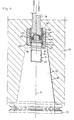
- FIG. 1 there is illustrated a tool machine spindle at 10.
- the spindle is operated in a conventional manner and therefore the means used therefor are not illustrated.
- a conical arbor 12 which is symmetrical around a central axis 11 has been received in a correspondingly conically designed recess 13 in the machine spindel 10.
- the conical arbor 12 is intended to carry a tool (not shows) in one end portion at which there is also provided a carrying flange 14.
- the arbor In its opposite end portion the arbor is provided with a threaded bore 15 in which a draw tap 17 having external threads 16 is intended to be threadably engaged.
- the lower end of said draw tap 17 could be made integral with the conical arbor 12 or it could be releasably connected with the arbor with some other type of clamping means.
- a clamping device which carries a tool and a conical arbor is provided inside the machine spindle, said clamping device comprising a draw bar 18 the lower end of which carries a radial flange portion 19 which is provided with an external thread 20 to be threadably connected with a corresponding internally threaded portion 21 of a clamping sleeve 22 which is arranged coaxially in relation to the draw bar whereby an elastic locking ring 24 is received in an interior recess 23 of said sleeve.
- the locking ring 24 has in its released position an exterior diameter corresponding with the diameter of said recess 23.
- the conical arbor 12 is carried by the draw tap 17 which is carried in the clamping sleeve 22 by arranging the locking ring 24 such that it is partially received in annular recess 25 on the draw bar whilst being in supporting abutment with an abutment surface 26′ provided by narrowing the entrance bore of said sleeve by means of a radially inwards extending flange portion 27.
- This abutment surface 26′ is provided as the lower end portion of an inclined transition surface 26 ⁇ between the central hole 23 of the sleeve and the axially extending innser surface 28 of said flange portion 27.
- said abutment surface 26′ has a smoothly rounded profile which as closely as possible corresponds with the profile of the locking ring 24. This enables provision of a sufficiently large contact surface which reduces the surface pressure. It is important that the material in said abutment surface 26′, the material in the metal segments 39 of said clamping ring and the material in the annular recess 25 of said draw bar are made of hardened material which facilitates maintenance of desired dimensional limitations of the device.
- a supporting element 29 is also received in the hole of the sleeve 22 consisting of a central neck portion 30 and a lower radially enlarged portion 31 so that a radial abutment 32 is obtained against which a number of spring washers 33 are resting.
- the lower end surface of said supporting element 29 is intended to abut against the locking ring 24.
- the supporting element 29 has the function of being an abutment for the locking ring 24 during the engagement phase.
- it shall accomplish a holding-up force which is larger than the axial force which by friction and impact of the conical angle of surface 26 affects the locking ring when the clamping sleeve is displaced backwards.
- it must be fixed axially which is accomplished by providing a number of pins 37 received in bores 36 around the flange portion 19 which via the washer 34 and the biassed spring washers 33 keeps it in position in relation to the spindle 10.
- a locking ring 24 is provided for the purpose of carrying the tool arbor 12 and the draw tap 17 connected therewith.
- This locking 24 is preferably in the shape of an O-ring composed of a number of spaced metal segments 39 which are kept together in O-ring fashion by vulcanized rubber segments 40 in the manner shown in Fig.2. This gives the ring 24 the ability to be compressed whilst having a sufficiently good carrying ability such as to axially carry the tool arbor 12 via the draw tap 17.
- the draw tap 17 is provided with an annular recess 25 for the receipt of the locking ring 24 on both sides of which axially extending guide surfaces 41 and 42 are provided.
- the axially lower guide surface 41 is intended to slide against inner surface 28 of clamping sleeve 22 with a clearance fit whereas the upper guide surface 42 is similarly intended to slide against the interior axial surface 28 of clamping sleeve during the assembling phase.
- the draw tap 17 is additionally provided with an entering beveled portion 44 the axial extent of which is selected so that at completion of the clamping of the tool arbor 12 by means of the draw bar 18 the upper end surface 45 of the draw tap 17 which extends perpendicularly from the central axis 11 is brought into abutment with a centrally located end surface 46 of the supporting element 29. It is found to be suitable to make the depth of the recess 25 in the draw tap 17 essentially equal with or somewhat less than one half of the cross sectional diameter of the locking ring 24. Furhter, both guide surfaces 41 and 42 of the draw tap 17 ought to be concentrical with same diameter in order to facilitate for the entrance and assembly of the draw tap into the clamping sleeve 22.
- the draw tap 17 is provided with a radial flange 47 located between the upper termination of threaded portion 16 and the guide surface 41, whereby said flange is arranged to abut against the end surface 48 of the arbor 12 which is facing the machine spindle.
- the draw bar 18 is arranged axially behind the package of spring washers 33.
- the release movement is accomplished by a suitable press force effected on the draw bar 18 of sufficient to press axially downwards the draw bar 18 and the clamping sleeve 22 rigidly connected therewith thereby enabling the locking ring 24 to expand, due to the inclination of transition surface 26 ⁇ , and adopt the position to be right of central axis 11 as shown in Fig. 4.
- the locking ring 24 has been given the possibility to slide along transition surface 26 ⁇ and by natural expansion adopting a position in which it is freely exposed from annular recess 25 of the draw tap 17 thus enabling the latter to become axially released to provide for change of tool.
- the clamping device has been described herein as useful in a tool clamping system for rotary tools.
- the invention is, however, also useful for connecting stationary turning tools with a tooling machine as well as in connection with other types of toolholders than traditional arbors.
Landscapes
- Engineering & Computer Science (AREA)
- Mechanical Engineering (AREA)
- Gripping On Spindles (AREA)
Applications Claiming Priority (2)
| Application Number | Priority Date | Filing Date | Title |
|---|---|---|---|
| SE8900342A SE462554B (sv) | 1989-02-01 | 1989-02-01 | Spaennanordning foer verktyg |
| SE8900342 | 1989-02-01 |
Publications (3)
| Publication Number | Publication Date |
|---|---|
| EP0383735A2 true EP0383735A2 (fr) | 1990-08-22 |
| EP0383735A3 EP0383735A3 (en) | 1990-12-12 |
| EP0383735B1 EP0383735B1 (fr) | 1993-07-14 |
Family
ID=20374913
Family Applications (1)
| Application Number | Title | Priority Date | Filing Date |
|---|---|---|---|
| EP90850031A Expired - Lifetime EP0383735B1 (fr) | 1989-02-01 | 1990-01-24 | Dispositif de serrage d'outil |
Country Status (5)
| Country | Link |
|---|---|
| US (1) | US5037254A (fr) |
| EP (1) | EP0383735B1 (fr) |
| JP (1) | JPH02269511A (fr) |
| DE (1) | DE69002172T2 (fr) |
| SE (1) | SE462554B (fr) |
Cited By (2)
| Publication number | Priority date | Publication date | Assignee | Title |
|---|---|---|---|---|
| US5118229A (en) * | 1991-06-04 | 1992-06-02 | Kennametal Inc. | Apparatus for transmitting motion to an off-axis rotary driven tool |
| EP1597037A4 (fr) * | 2002-12-30 | 2009-10-28 | Mate Precision Tooling Inc | Outil de poinconnage |
Families Citing this family (9)
| Publication number | Priority date | Publication date | Assignee | Title |
|---|---|---|---|---|
| US5203654A (en) * | 1992-03-30 | 1993-04-20 | Henderson Jerry N | Replaceable tang and tool combination |
| US5542792A (en) * | 1993-12-21 | 1996-08-06 | Waukesha Cutting Tools, Inc. | Cutting device with removable nosepiece |
| US6082516A (en) * | 1998-01-22 | 2000-07-04 | Amada Engineering & Service Co., Inc. | Variable height adjustable punch assembly having quick release stripper plate |
| US6047621A (en) * | 1998-02-27 | 2000-04-11 | Elba Electronetics, Inc. | Quick change adjustable punch tool assembly and method of adjustment |
| CA2360301A1 (fr) | 2001-10-26 | 2003-04-26 | Shearpress Sales Inc. | Appareil et methode de compensation des deviations angulaires d'une piece a ouvrer |
| US7175184B1 (en) | 2003-10-24 | 2007-02-13 | Pilling Weck Incorporated | Collect tool holder and method of making same |
| DE102005028563B4 (de) * | 2005-06-21 | 2021-06-10 | Contitech Vibration Control Gmbh | Lager |
| GB201207511D0 (en) * | 2012-04-30 | 2012-06-13 | Airbus Operations Ltd | Bush assembly |
| EP3424645B1 (fr) * | 2017-07-07 | 2021-05-05 | Von Arx AG | Accouplement destiné à relier une tête de changement d'outil à une partie d'un appareil de presse |
Family Cites Families (9)
| Publication number | Priority date | Publication date | Assignee | Title |
|---|---|---|---|---|
| US2713811A (en) * | 1950-05-26 | 1955-07-26 | New Britain Machine Co | Tool spindle mechanism |
| US3043614A (en) * | 1961-06-30 | 1962-07-10 | Albert C Eichmann | Load releasing lock-on coupling |
| US3168322A (en) * | 1962-10-18 | 1965-02-02 | Scully Jones & Co | Chucking device for machine tool spindle and tool holder for use therewith |
| US3651739A (en) * | 1970-01-30 | 1972-03-28 | New Britain Machine Co | Machine tool |
| JPS5367181A (en) * | 1976-11-27 | 1978-06-15 | Fanuc Ltd | Machine tool |
| EP0101917B1 (fr) * | 1982-07-30 | 1986-05-28 | Gerhard Rall | Outil d'alésage |
| JPS59142037A (ja) * | 1983-02-03 | 1984-08-15 | Toyoda Mach Works Ltd | スピンドルヘツドにおける工具クランプ装置 |
| US4773800A (en) * | 1987-01-09 | 1988-09-27 | Yamazaki Mazak Corporation | Pull stud |
| DE8700618U1 (de) * | 1987-01-14 | 1987-03-05 | Jamann GmbH, 56379 Horhausen | Kupplungselement, insbesondere zum kraft- und formschlüssigen Verbinden eines Werkzeugkopfes mit einem Werkzeugträger |
-
1989
- 1989-02-01 SE SE8900342A patent/SE462554B/sv not_active IP Right Cessation
-
1990
- 1990-01-18 US US07/466,765 patent/US5037254A/en not_active Expired - Fee Related
- 1990-01-24 EP EP90850031A patent/EP0383735B1/fr not_active Expired - Lifetime
- 1990-01-24 DE DE90850031T patent/DE69002172T2/de not_active Expired - Fee Related
- 1990-01-31 JP JP2019357A patent/JPH02269511A/ja active Pending
Cited By (2)
| Publication number | Priority date | Publication date | Assignee | Title |
|---|---|---|---|---|
| US5118229A (en) * | 1991-06-04 | 1992-06-02 | Kennametal Inc. | Apparatus for transmitting motion to an off-axis rotary driven tool |
| EP1597037A4 (fr) * | 2002-12-30 | 2009-10-28 | Mate Precision Tooling Inc | Outil de poinconnage |
Also Published As
| Publication number | Publication date |
|---|---|
| EP0383735A3 (en) | 1990-12-12 |
| DE69002172D1 (de) | 1993-08-19 |
| SE8900342D0 (sv) | 1989-02-01 |
| DE69002172T2 (de) | 1993-10-21 |
| EP0383735B1 (fr) | 1993-07-14 |
| US5037254A (en) | 1991-08-06 |
| JPH02269511A (ja) | 1990-11-02 |
| SE462554B (sv) | 1990-07-16 |
Similar Documents
| Publication | Publication Date | Title |
|---|---|---|
| US4997325A (en) | Chuck for axially clamping two machine parts which are releasable from each other | |
| JP3986429B2 (ja) | クランプ装置 | |
| US4840520A (en) | Mounting device having a conical shank | |
| KR100259551B1 (ko) | 파지력이 증가된 잠금기구를 구비한 공구유니트 클램핑장치 | |
| EP0383735A2 (fr) | Dispositif de serrage d'outil | |
| US4726268A (en) | Clamping apparatus for holding a toolholder shank | |
| US6145850A (en) | Diaphragm chuck | |
| JP4016295B2 (ja) | 油圧機械式チャック | |
| US4068559A (en) | Tool fastening device | |
| JPS643602B2 (fr) | ||
| US4945793A (en) | Tool coupling | |
| EP0387228B1 (fr) | Accouplement d'outil entre un porte-outil et une broche de machine | |
| KR100584162B1 (ko) | 공작기계용 공구 커플링 시스템 | |
| US5820135A (en) | Counter centrifugal chuck and mounting systems | |
| IE903198A1 (en) | Device for the connection of two tool portions of machine¹tool | |
| EP0684884B1 (fr) | Dispositif de fixation pour fraiseuses et machines similaires et adaptable a des dimensions de support differentes | |
| US6547259B2 (en) | Master and insert jaw system | |
| SU1657278A1 (ru) | Быстросменный инструментальный блок | |
| KR0177625B1 (ko) | Cnc 선반의 서브 스핀들에 설치된 공작물 배출장치 | |
| RU219109U1 (ru) | Устройство для осевой фиксации заготовок | |
| SU1473906A1 (ru) | Цанговый патрон дл концевого инструмента | |
| SU984722A1 (ru) | Переходный сменный патрон | |
| SU1745419A1 (ru) | Патрон дл закреплени концевого режущего инструмента | |
| RU1787702C (ru) | Зажимной патрон | |
| KR100299494B1 (ko) | 공작물 고정장치 |
Legal Events
| Date | Code | Title | Description |
|---|---|---|---|
| PUAI | Public reference made under article 153(3) epc to a published international application that has entered the european phase |
Free format text: ORIGINAL CODE: 0009012 |
|
| AK | Designated contracting states |
Kind code of ref document: A2 Designated state(s): DE FR GB IT SE |
|
| PUAL | Search report despatched |
Free format text: ORIGINAL CODE: 0009013 |
|
| AK | Designated contracting states |
Kind code of ref document: A3 Designated state(s): DE FR GB IT SE |
|
| 17P | Request for examination filed |
Effective date: 19901227 |
|
| 17Q | First examination report despatched |
Effective date: 19920626 |
|
| GRAA | (expected) grant |
Free format text: ORIGINAL CODE: 0009210 |
|
| ITF | It: translation for a ep patent filed | ||
| AK | Designated contracting states |
Kind code of ref document: B1 Designated state(s): DE FR GB IT SE |
|
| PG25 | Lapsed in a contracting state [announced via postgrant information from national office to epo] |
Ref country code: SE Effective date: 19930714 |
|
| REF | Corresponds to: |
Ref document number: 69002172 Country of ref document: DE Date of ref document: 19930819 |
|
| ET | Fr: translation filed | ||
| PGFP | Annual fee paid to national office [announced via postgrant information from national office to epo] |
Ref country code: FR Payment date: 19940111 Year of fee payment: 5 |
|
| PGFP | Annual fee paid to national office [announced via postgrant information from national office to epo] |
Ref country code: GB Payment date: 19940114 Year of fee payment: 5 |
|
| PGFP | Annual fee paid to national office [announced via postgrant information from national office to epo] |
Ref country code: DE Payment date: 19940121 Year of fee payment: 5 |
|
| PLBE | No opposition filed within time limit |
Free format text: ORIGINAL CODE: 0009261 |
|
| STAA | Information on the status of an ep patent application or granted ep patent |
Free format text: STATUS: NO OPPOSITION FILED WITHIN TIME LIMIT |
|
| 26N | No opposition filed | ||
| PG25 | Lapsed in a contracting state [announced via postgrant information from national office to epo] |
Ref country code: GB Effective date: 19950124 |
|
| GBPC | Gb: european patent ceased through non-payment of renewal fee |
Effective date: 19950124 |
|
| PG25 | Lapsed in a contracting state [announced via postgrant information from national office to epo] |
Ref country code: FR Effective date: 19950929 |
|
| PG25 | Lapsed in a contracting state [announced via postgrant information from national office to epo] |
Ref country code: DE Effective date: 19951003 |
|
| REG | Reference to a national code |
Ref country code: FR Ref legal event code: ST |
|
| PG25 | Lapsed in a contracting state [announced via postgrant information from national office to epo] |
Ref country code: IT Free format text: LAPSE BECAUSE OF NON-PAYMENT OF DUE FEES Effective date: 20050124 |