EP0383930A1 - Wasserstrahldüse für webstühle - Google Patents
Wasserstrahldüse für webstühle Download PDFInfo
- Publication number
- EP0383930A1 EP0383930A1 EP89907305A EP89907305A EP0383930A1 EP 0383930 A1 EP0383930 A1 EP 0383930A1 EP 89907305 A EP89907305 A EP 89907305A EP 89907305 A EP89907305 A EP 89907305A EP 0383930 A1 EP0383930 A1 EP 0383930A1
- Authority
- EP
- European Patent Office
- Prior art keywords
- water jet
- jet nozzle
- stabilizer
- loom
- corrosion resistance
- Prior art date
- Legal status (The legal status is an assumption and is not a legal conclusion. Google has not performed a legal analysis and makes no representation as to the accuracy of the status listed.)
- Granted
Links
Images

Classifications
-
- D—TEXTILES; PAPER
- D03—WEAVING
- D03D—WOVEN FABRICS; METHODS OF WEAVING; LOOMS
- D03D47/00—Looms in which bulk supply of weft does not pass through shed, e.g. shuttleless looms, gripper shuttle looms, dummy shuttle looms
- D03D47/28—Looms in which bulk supply of weft does not pass through shed, e.g. shuttleless looms, gripper shuttle looms, dummy shuttle looms wherein the weft itself is projected into the shed
- D03D47/32—Looms in which bulk supply of weft does not pass through shed, e.g. shuttleless looms, gripper shuttle looms, dummy shuttle looms wherein the weft itself is projected into the shed by liquid jet
-
- B—PERFORMING OPERATIONS; TRANSPORTING
- B05—SPRAYING OR ATOMISING IN GENERAL; APPLYING FLUENT MATERIALS TO SURFACES, IN GENERAL
- B05B—SPRAYING APPARATUS; ATOMISING APPARATUS; NOZZLES
- B05B1/00—Nozzles, spray heads or other outlets, with or without auxiliary devices such as valves, heating means
- B05B1/34—Nozzles, spray heads or other outlets, with or without auxiliary devices such as valves, heating means designed to influence the nature of flow of the liquid or other fluent material, e.g. to produce swirl
- B05B1/3402—Nozzles, spray heads or other outlets, with or without auxiliary devices such as valves, heating means designed to influence the nature of flow of the liquid or other fluent material, e.g. to produce swirl to avoid or reduce turbulence, e.g. with fluid flow straightening means
Definitions
- the present invention relates to a water jet nozzle for use with a high-speed loom.
- This type of prior art water jet nozzle is so constructed that an orifice E and a needle F inserted concentrically with the orifice E are provided at a top of a body D formed with a pool C communicating with a water injection hole B of a holder A.
- a structure of the water jet nozzle is that the water injected via injection hole B of the holder A jet out from a gap between the orifice E and the needle F.
- the water jet nozzle performs a function to intermittently feed, between warps stretched from a tip of the needle F to an unillustrated loom, a weft yarn charged in from a cavity G of the needle F.
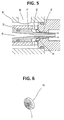
- a resinous stabilizer H having a construction shown in Fig. 6 is so disposed as to be contiguous to a rear end of the orifice E composed of a hardened steel.
- the resinous stabilizer H is manufactured simply by injection molding and also simply assembled by setting it in a space at a rear part of the orifice E made of the hardened steel.
- the stabilizer H exhibits a remarkable effect for a loom of which a weftwise feeding number is approximately 400 - 750 times/min under a water pressure of about 25 kg/cm2 .
- a water pressure is 30 - 40kg/cm2; a water flow rate reaches 30 - 40 m/sec. and the number of insertions of weft yarn exceeds 1000 times/min.
- the material of which the stabilizer is formed is insufficient in its hardness and strength, resulting in an intensive wear caused by the water flow and in a short life span thereof. Besides, it is impossible to set a thickness of a blade unit to 0.2 mm or under. At a high flow rate of more than 30 m/sec, the water pressure drops due to a fluid resistance, and the weftwise feeding number is limited to 750 times/min. Under such conditions, it is absolutely impossible to correspond to high-speed feeding of the weft yarn.
- the conventional water jet nozzle generates water jets from the orifice and needle, and the unit for feeding out the weft yarn is made of a hardened steel at best.
- wear resistance and corrosion resistance are not sufficient, as a result of which the device decreases in its life span and associated components have to be replaced.
- the resinous stabilizer conceived as a component to be replaced decrease in availability factor, but also the loom itself is thereby reduced in the same factor.
- Another object of the present invention is to provide a water jet nozzle capable of reducing a resistance caused on the occasion of straightening for water jets.
- Still another object of the present invention is to provide a water jet nozzle capable of improving a hyperfine machinability of a needle tip and enhancing a function of the nozzle itself.
- a water jet nozzle according to the present invention is constructed in such a way that a high pressure water flow from a needle and an orifice is jetted; a unit for feeding out a weft yarn is composed of a material having a high hardness and an corrosion resistance; and the orifice is made integral with a stabilizer.
- the material of high hardness and corrosion resistance mentioned involves the use of a sintered cemented carbides, cermets and ceramics.
- An arbitrary material can be employed on condition that a modulus of elasticity is more than 1.5 X 10⁴ kg/mm2 and a hardness is H R A 85 or greater.
- a flexural strength of material is therefore 50 kg/mm2, preferably 75 kg/mm2 or larger.
- the sintered cemented carbide includes materials grouped in accordance with JIS symbols, P, M, K, V and E which are used for cutting tools, wear resistant tools and mining tools.
- a cermets group there may be exemplified materials mainly composed of titanium carbide exhibiting strengths, wear resistance, corrosion resistance and a hyperfine machinability. These materials are effective in aviating the foregoing problems in the prior arts.
- the ceramic materials are utilized, in the great majority of cases, they exhibit more excellent corrosion resistance and wear resistance than in the sintered cemented carbides and cermets. While on the other hand, a good many ceramic materials are unsatisfactory in terms of their strengths and are therefore to be selected depending on whether they exhibit a hyperfine machinability or not.
- a wide variety of ceramic materials are prepared, i.e., A1 2 0 3 , Si 3 N 4 , Zr0 2 and SiC.
- Other materials chiefly composed of nitride, boride and carbide or composites obtained by mixing two or more kinds of these materials are also exemplified.
- a flexural strength is at least 50 kg/mm2 or above.
- the flexural strength is 75 kg/mm2 or greater. Deteriorations such as chips can be minimized by selecting the ceramic materials which meet such requirements.
- a member formed of an Si 3 N 5 group material or a Zr0 2 group material or formed of a composite obtained by adding other oxide, carbide, nitride and boride among the foregoing materials thereto is capable of providing a well-conditioned finish and decreasing a thickness of each blade of the stabilizer. Hence, it is possible to reduce a resistance during the straightening for the water jets, ameliorate the hyperfine machinability of the needle tip and enhance the function of the nozzle itself.
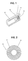
- Fig. 1 is a view sectionally showing an outer shape of a nozzle member 1 according to the present invention.
- the nozzle member 1 is constructed such that, as illustrated in Fig. 1, a stabilizer 5 is integrally formed through an annular groove 4 for adjusting a water flow in rear of an orifice 3 formed in an interior of a body 2 at its rear end.
- the stabilizer 5 is, referring to Fig. 2 showing its configuration in section, formed with more than 10 streaks of slits 6 each having the same width at equal spacings.
- Equalization of the spacings between the slits 6 is of much importance in terms of a high-speed straightening of a water flow.
- the best condition has been confirmed from experiments, wherein the number of slits each having a width of 0.5 mm is 16 to 18 when the number of revolutions of a loom is 900 rpm and a pump water pressure is 35 kg/cm2.
- the number of slits 6 should be adjusted depending on a size of an inside diameter of the stabilizer.
- a thickness of top end of the blade 7 shown in Fig. 2 is 0.1 1 mm or under, preferably smaller than 0.05 mm. It is feasible to obtain a jet water flow having a higher convergence as it approaches a knife edge.
- a thickness of an outside diameter of each of the blades 7 for shaping the slits 6 of the stabilizer 5 is to be set preferably to 0.5 mm through 1.2 mm.
- a top end 8 of the blade 7 may be formed at a right angle or make some angles or rounded with a radius. However, a preferable formation thereof eliminates a possibility of producing chips.
- a corner of an orifice inlet 11 facing an annular groove 4 formed to reduce a resistance of a rectified pressure water is formed in a round shape of at least 0.5 R.
- An angle 0 of a tapered portion 12 is, as illustrated in Fig.
- the numeral 9 represents a needle for feeding out the weft yarn set in a central opening of the orifice 3 of the nozzle member 1 as well as in a central part of the stabilizer 5 shown in Fig. 1.
- Injected water W completely rectified by the stabilizer 5 in cooperation with the annular groove 4 is jetted between the needle 9 and the orifice 3.
- an edge angle of a top end 10 of the orifice 3 is preferably larger than 90° under such a condition that the rectified water W runs at a high flow rate of 30 - 40 m/sec. More preferably, the edge angle is set at 95° to 115°, with the result that a water jet flow having a good convergence can be attained without splitting the flow.
- An additional condition for obtaining the highly convergent water jet flow is that the edge portion having an angle of 95° through 115° is shaped to provide a smooth surface without producing the chips to the greatest possible degree.
- the water jet nozzle assuming configurations shown in the foregoing figures is composed of partially stabilized zirconia and other many materials in the manner discussed above and is applied to a loom in which synthetic long fibers are arranged with a taffeta width of 1200 - 1800 mm. In this case, weaving can be effected at a higher velocity of 200 - 400 times/min (approximately 1.5-fold velocity) than in the conventional nozzle.
- the water jet nozzle of the present invention can be applied to the high-speed loom by which fabrics that are required to have a high quality are manufactured.
Landscapes
- Engineering & Computer Science (AREA)
- Textile Engineering (AREA)
- Looms (AREA)
Applications Claiming Priority (3)
| Application Number | Priority Date | Filing Date | Title |
|---|---|---|---|
| JP63164531A JPH0219546A (ja) | 1988-07-01 | 1988-07-01 | 織機用ウォータージェットノズル |
| JP164531/88 | 1988-07-01 | ||
| PCT/JP1989/000634 WO1990000211A1 (en) | 1988-07-01 | 1989-06-27 | Water jet nozzle for looms |
Publications (3)
| Publication Number | Publication Date |
|---|---|
| EP0383930A1 true EP0383930A1 (de) | 1990-08-29 |
| EP0383930A4 EP0383930A4 (en) | 1990-10-24 |
| EP0383930B1 EP0383930B1 (de) | 1995-03-22 |
Family
ID=15794935
Family Applications (1)
| Application Number | Title | Priority Date | Filing Date |
|---|---|---|---|
| EP89907305A Expired - Lifetime EP0383930B1 (de) | 1988-07-01 | 1989-06-27 | Wasserstrahldüse für webstühle |
Country Status (5)
| Country | Link |
|---|---|
| US (1) | US5119863A (de) |
| EP (1) | EP0383930B1 (de) |
| JP (1) | JPH0219546A (de) |
| DE (1) | DE68921873T2 (de) |
| WO (1) | WO1990000211A1 (de) |
Families Citing this family (9)
| Publication number | Priority date | Publication date | Assignee | Title |
|---|---|---|---|---|
| JP2997949B2 (ja) * | 1990-04-17 | 2000-01-11 | アイ・アール・オー エー・ビー | 紡糸通しシステムのための方法および装置 |
| US5462095A (en) * | 1993-02-08 | 1995-10-31 | Hokuriku Seikei Industrial Co., Ltd. | Picking device with selected spools for a water-jet loom |
| WO1994023104A1 (fr) * | 1993-04-01 | 1994-10-13 | Toray Industries, Inc. | Procede et appareil permettant de fabriquer un tisse de fibres de carbone avec une machine a jet d'eau |
| US5402938A (en) * | 1993-09-17 | 1995-04-04 | Exair Corporation | Fluid amplifier with improved operating range using tapered shim |
| JP2003313754A (ja) * | 2002-04-26 | 2003-11-06 | Tsudakoma Corp | 水噴射式織機の緯入ノズル |
| JP3934026B2 (ja) * | 2002-10-18 | 2007-06-20 | 津田駒工業株式会社 | 流体噴射式織機の緯入れノズル |
| DE102007024247B3 (de) * | 2007-05-15 | 2008-11-06 | Lechler Gmbh | Hochdruckdüse und Verfahren zum Herstellen einer Hochdruckdüse |
| CN106012245A (zh) * | 2016-07-28 | 2016-10-12 | 吴江金叶织造有限公司 | 一种用于喷气织机的主喷嘴 |
| CN110644119A (zh) * | 2018-06-27 | 2020-01-03 | 无锡市荣跃纺机专件厂 | 喷水编织机陶瓷喷嘴 |
Family Cites Families (16)
| Publication number | Priority date | Publication date | Assignee | Title |
|---|---|---|---|---|
| CH308867A (de) * | 1953-02-20 | 1955-08-15 | Mira Z Na Pletene A Stavkove Z | Mit einer Flüssigkeitsdüse verbundene Kolbenpumpe für Webstühle. |
| JPS3420278Y1 (de) * | 1954-08-30 | 1959-12-10 | ||
| US3486700A (en) * | 1967-12-14 | 1969-12-30 | L N B Co | Nozzle |
| US4074727A (en) * | 1975-06-09 | 1978-02-21 | Joseph Rene Cornellier | Liquid supply system and nozzle for jet weaving looms |
| JPS5319257Y2 (de) * | 1975-07-05 | 1978-05-22 | ||
| JPS5212273U (de) * | 1975-07-12 | 1977-01-28 | ||
| JPS5212273A (en) * | 1975-07-19 | 1977-01-29 | Ishikawajima Harima Heavy Ind | Method and device for blow molding multiilayer molded article having reinforced structure |
| CH609107A5 (en) * | 1975-12-30 | 1979-02-15 | Enshu Seisaku Kk | Injection mouthpiece for a water-jet loom |
| JPS5319257A (en) * | 1976-08-06 | 1978-02-22 | Hamasawa Kogyo:Kk | Shaving foam heating device |
| US4253611A (en) * | 1978-06-05 | 1981-03-03 | Delta Materials Research Limited | Jet nozzles |
| US4531555A (en) * | 1983-01-19 | 1985-07-30 | Toray Industries, Inc. | Yarn cutter for shuttleless loom |
| CA1209182A (en) * | 1984-01-04 | 1986-08-05 | Charles E. Capes | Wear resistant atomizing nozzle assembly |
| JPS6141348A (ja) * | 1984-07-27 | 1986-02-27 | 増田 照雄 | 緯入れ用ノズル |
| JPS61113857A (ja) * | 1984-11-09 | 1986-05-31 | 増田 照雄 | 緯入れ用ノズル |
| YU45690B (sh) * | 1984-12-22 | 1992-07-20 | Krka Tovarna Zdraviln.Sol.O. | Postopek za pripravo 9-(2-hidroksietoksimetil)-gvanina |
| JPH0822716B2 (ja) * | 1985-10-11 | 1996-03-06 | 株式会社寺岡製作所 | テープの巻取方法 |
-
1988
- 1988-07-01 JP JP63164531A patent/JPH0219546A/ja active Granted
-
1989
- 1989-06-27 WO PCT/JP1989/000634 patent/WO1990000211A1/ja not_active Ceased
- 1989-06-27 DE DE68921873T patent/DE68921873T2/de not_active Expired - Fee Related
- 1989-06-27 EP EP89907305A patent/EP0383930B1/de not_active Expired - Lifetime
- 1989-06-27 US US07/465,172 patent/US5119863A/en not_active Expired - Fee Related
Also Published As
| Publication number | Publication date |
|---|---|
| EP0383930A4 (en) | 1990-10-24 |
| US5119863A (en) | 1992-06-09 |
| JPH0219546A (ja) | 1990-01-23 |
| EP0383930B1 (de) | 1995-03-22 |
| WO1990000211A1 (en) | 1990-01-11 |
| DE68921873D1 (de) | 1995-04-27 |
| JPH0418053B2 (de) | 1992-03-26 |
| DE68921873T2 (de) | 1995-12-14 |
Similar Documents
| Publication | Publication Date | Title |
|---|---|---|
| US5119863A (en) | Water jet nozzle for loom | |
| US3863822A (en) | Nozzle device for producing a fluid jet | |
| ATE369451T1 (de) | Hilfsdüse für eine webmachine | |
| KR102448195B1 (ko) | 래피어 직기용 에어 부상방식 위사 정렬장치 | |
| KR940010635B1 (ko) | 직기용 워터제트노즐 | |
| US4987930A (en) | Auxiliary sub-nozzle for fluid jet loom | |
| JPH0411048A (ja) | 織機用ウォータージェットノズルにおけるノズル部の構造 | |
| EP0516587A1 (de) | Hilfsdüse für eine pneumatische Webmaschine | |
| JPH0318525Y2 (de) | ||
| JP2597396Y2 (ja) | 織機用空気噴射ノズル | |
| JP2550495Y2 (ja) | 織機用空気噴射ノズル | |
| JPH0684576B2 (ja) | 流体噴射式織機における補助ノズル装置 | |
| JP2003313754A (ja) | 水噴射式織機の緯入ノズル | |
| JP2000119937A (ja) | 収束性に優れた緯入れノズル | |
| TW369573B (en) | Sub-nozzle for an air injection type weaving machine | |
| JPH0522580U (ja) | 織機用空気噴射ノズル | |
| JP3537003B2 (ja) | 水噴射式織機 | |
| JPH0544139A (ja) | 流体噴射式織機用のサブノズル | |
| WO1994011553A1 (fr) | Buse auxiliaire pour metier a tisser de type a injection d'air | |
| US595416A (en) | Loom-shuttle | |
| JPH0665776B2 (ja) | 流体噴射式織機用の補助ノズル | |
| JP2020063546A (ja) | 空気噴射式織機のサブノズル | |
| CN111926445A (zh) | 空气喷射式织机用的副喷嘴 | |
| JPH08113843A (ja) | 織機用ヘルドバーおよびヘルド | |
| JP2003155644A (ja) | 水噴射式織機の緯入ノズル |
Legal Events
| Date | Code | Title | Description |
|---|---|---|---|
| PUAI | Public reference made under article 153(3) epc to a published international application that has entered the european phase |
Free format text: ORIGINAL CODE: 0009012 |
|
| 17P | Request for examination filed |
Effective date: 19900618 |
|
| AK | Designated contracting states |
Kind code of ref document: A1 Designated state(s): DE FR GB IT |
|
| A4 | Supplementary search report drawn up and despatched |
Effective date: 19900905 |
|
| AK | Designated contracting states |
Kind code of ref document: A4 Designated state(s): DE FR GB IT |
|
| 17Q | First examination report despatched |
Effective date: 19920304 |
|
| GRAA | (expected) grant |
Free format text: ORIGINAL CODE: 0009210 |
|
| AK | Designated contracting states |
Kind code of ref document: B1 Designated state(s): DE FR GB IT |
|
| REF | Corresponds to: |
Ref document number: 68921873 Country of ref document: DE Date of ref document: 19950427 |
|
| ET | Fr: translation filed | ||
| ITF | It: translation for a ep patent filed | ||
| PLBE | No opposition filed within time limit |
Free format text: ORIGINAL CODE: 0009261 |
|
| STAA | Information on the status of an ep patent application or granted ep patent |
Free format text: STATUS: NO OPPOSITION FILED WITHIN TIME LIMIT |
|
| 26N | No opposition filed | ||
| PGFP | Annual fee paid to national office [announced via postgrant information from national office to epo] |
Ref country code: GB Payment date: 19990623 Year of fee payment: 11 |
|
| PGFP | Annual fee paid to national office [announced via postgrant information from national office to epo] |
Ref country code: FR Payment date: 19990630 Year of fee payment: 11 |
|
| PGFP | Annual fee paid to national office [announced via postgrant information from national office to epo] |
Ref country code: DE Payment date: 19990830 Year of fee payment: 11 |
|
| PG25 | Lapsed in a contracting state [announced via postgrant information from national office to epo] |
Ref country code: GB Free format text: LAPSE BECAUSE OF NON-PAYMENT OF DUE FEES Effective date: 20000627 |
|
| GBPC | Gb: european patent ceased through non-payment of renewal fee |
Effective date: 20000627 |
|
| PG25 | Lapsed in a contracting state [announced via postgrant information from national office to epo] |
Ref country code: FR Free format text: LAPSE BECAUSE OF NON-PAYMENT OF DUE FEES Effective date: 20010228 |
|
| REG | Reference to a national code |
Ref country code: FR Ref legal event code: ST |
|
| PG25 | Lapsed in a contracting state [announced via postgrant information from national office to epo] |
Ref country code: DE Free format text: LAPSE BECAUSE OF NON-PAYMENT OF DUE FEES Effective date: 20010403 |
|
| PG25 | Lapsed in a contracting state [announced via postgrant information from national office to epo] |
Ref country code: IT Free format text: LAPSE BECAUSE OF NON-PAYMENT OF DUE FEES;WARNING: LAPSES OF ITALIAN PATENTS WITH EFFECTIVE DATE BEFORE 2007 MAY HAVE OCCURRED AT ANY TIME BEFORE 2007. THE CORRECT EFFECTIVE DATE MAY BE DIFFERENT FROM THE ONE RECORDED. Effective date: 20050627 |