EP0384010A1 - Verfahren zum Fördern von warmgewalztem Draht und Vorrichtung dafür - Google Patents
Verfahren zum Fördern von warmgewalztem Draht und Vorrichtung dafür Download PDFInfo
- Publication number
- EP0384010A1 EP0384010A1 EP89121075A EP89121075A EP0384010A1 EP 0384010 A1 EP0384010 A1 EP 0384010A1 EP 89121075 A EP89121075 A EP 89121075A EP 89121075 A EP89121075 A EP 89121075A EP 0384010 A1 EP0384010 A1 EP 0384010A1
- Authority
- EP
- European Patent Office
- Prior art keywords
- wire rod
- conveyer
- center line
- arm
- guide means
- Prior art date
- Legal status (The legal status is an assumption and is not a legal conclusion. Google has not performed a legal analysis and makes no representation as to the accuracy of the status listed.)
- Granted
Links
Images



Classifications
-
- B—PERFORMING OPERATIONS; TRANSPORTING
- B21—MECHANICAL METAL-WORKING WITHOUT ESSENTIALLY REMOVING MATERIAL; PUNCHING METAL
- B21F—WORKING OR PROCESSING OF METAL WIRE
- B21F23/00—Feeding wire in wire-working machines or apparatus
-
- B—PERFORMING OPERATIONS; TRANSPORTING
- B21—MECHANICAL METAL-WORKING WITHOUT ESSENTIALLY REMOVING MATERIAL; PUNCHING METAL
- B21C—MANUFACTURE OF METAL SHEETS, WIRE, RODS, TUBES, PROFILES OR LIKE SEMI-MANUFACTURED PRODUCTS OTHERWISE THAN BY ROLLING; AUXILIARY OPERATIONS USED IN CONNECTION WITH METAL-WORKING WITHOUT ESSENTIALLY REMOVING MATERIAL
- B21C47/00—Winding-up, coiling or winding-off metal wire, metal band or other flexible metal material characterised by features relevant to metal processing only
- B21C47/26—Special arrangements with regard to simultaneous or subsequent treatment of the material
- B21C47/262—Treatment of a wire, while in the form of overlapping non-concentric rings
-
- C—CHEMISTRY; METALLURGY
- C21—METALLURGY OF IRON
- C21D—MODIFYING THE PHYSICAL STRUCTURE OF FERROUS METALS; GENERAL DEVICES FOR HEAT TREATMENT OF FERROUS OR NON-FERROUS METALS OR ALLOYS; MAKING METAL MALLEABLE, e.g. BY DECARBURISATION OR TEMPERING
- C21D9/00—Heat treatment, e.g. annealing, hardening, quenching or tempering, adapted for particular articles; Furnaces therefor
- C21D9/52—Heat treatment, e.g. annealing, hardening, quenching or tempering, adapted for particular articles; Furnaces therefor for wires; for strips ; for rods of unlimited length
- C21D9/54—Furnaces for treating strips or wire
- C21D9/56—Continuous furnaces for strip or wire
- C21D9/573—Continuous furnaces for strip or wire with cooling
- C21D9/5732—Continuous furnaces for strip or wire with cooling of wires; of rods
Definitions
- the present invention relates to a method for transporting hot-rolled wire rod and an apparatus therefor.
- a mist-cooling method is proposed.
- a method wherein an air-blast mist produced by mixing water with the air-blast is used, a method wherein a mist produced by spraying water is used, and the like are pointed out as the mist cooling method.
- the side edge portions of rings of wire rod, which is transported in a state such that said wire rod is in the form of continuous series of loops, in the direction of the width of a conveyer overlap each other. If the rings of wire rod which overlap each other are not shifted one from another, the wire rod is not uniformly cooled and there occurs a deviation of strength and ductility of the wire rod. In consequence, the wire rod which can be put to practical use cannot be manufactured.
- a method, wherein conveyer rollers are arranged at a certain interval, diameters of both ends or one end of the roller at every several rollers are made large and wire rod is cooled by moving up-and-down the side edge portions of wire rod, is disclosed in a Japanese Utility Model Application Laid Open No.58839/74.
- Those methods are, however, substantially not effective in mist cooling of the wire rod when time of separation of the rings of wire rod one from another is short and a cooling rate is from 15 to 30 °C.
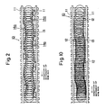
- FIG.10 An air patenting method as shown in Fig.10 is disclosed in a Japanese Patent Application Laid Open No. 15609/74.
- vertical rollers 12 are alternately arranged at a predetermined interval on side walls 11 of conveyer 10.
- Wire rod 13 is moved in zigzags by the vertical rollers 12.
- the wire rod 13 is cooled by air during its movement.
- the present invention provides a method for transporting hot-rolled wire rod, comprising: transporting a hot-rolled wire rod on a conveyor in a state such that siad wire rod is in the form of continuous series of loops, said wire rod being cooled; changing directions of movements of said wire rod alternately to the left and to the right relative to a center line of a conveyer at an interval of d/3 to 2d of a diameter "d" of a ring of said wire rod; and shifting the center of the ring of said wire rod from the center line of the conveyer by a length of 2d/100 to 30d/100 at its maximum.
- the present invention also provides an apparatus for transporting hot-rolled wire rod comprising: a conveyer for transporting a hot-rolled wire rod in a state such that siad wire rod is in the form of continuous series of loops; and guide means alternately arranged in an upper portion of the side of said conveyer for changing directions of movements of said wire rod alternately to the left and to the right relative to a center line of a conveyer.
- the present invention provides an apparatus for transporting hot-rolled wire rod comprising: a conveyer for transporting a wire rod in a state such that said wire rod is in the form of continuous series of loops; side walls arranged in zigzags facing each other on both sides of the conveyer to have said wire rod move in zigzags with the center line of the conveyer as the center, said side walls including a side wall arranged toward the center line of the conveyer relative to the direction of movement of said wire rod and a side wall arranged away from the center line of the conveyer; and a guide member arranged on the side walls arranged toward the center line of the conveyer.
- Fig.1 (A) is a top plan view illustrating a state of portions of wire rod 13, where rings of the wire rod 13 overlap each other, in the case of not moving the wire rod in zigzags.
- the rings of the wire rod overlap each other in multiple layers in the side edge portion of the conveyer.
- Directions of movements of the wire rod are desired to be alternately changed to the left and to the right relative to the center line of the conveyer at an interval of d/3 to 2d of a diameter of the wire rod.
- the interval is less than d/3, the directions of movements of the wire rod have to be changed at a wide angle to obtain a desired amount of zigzag movement of the wire rod. Since the directions of movements of the wire rod are changed at a wide angle, resistance, with which the wire rod meets, grows large. When the interval exceeds 2d, the number of the zigzag movements decrease. In consequence, the wire rod cannot be uniformly cooled. Diameters of the rings of hot-rolled wire rod are usually within a range of 900 to 1300 mm.
- the maximum shift of the center of the ring of the wire rod from the center line of the conveyer namely, the push-in length of the wire rod is desired to be 2d/100 to 30d/100.
- the push-in length of the wire rod is less than 2d/100, the rings which overlap each other cannot be shifted one from another. Therefore, the wire rod cannot be unifomly cooled.
- the push-in length of the wire rod exceeds 30d/100, the resistance, with which the wire rod meets during its transportation, increases and a width of the conveyer is required to be made large. Therefore, such push-in length is not favorable from a viewpoint of equipment.
- the wire rod When the push-in length of the wire rod is 2d/100 or more and less than 8d/100, the wire rod can be uniformly cooled though the push-in length of the wire rod is small. When the push-in length of the wire rod is more than 24d/100 and 30d/100 or less, the push-in length of the wire rod grows large, but the wire rod can be uniformly cooled. The push-in length of the wire rod of 8d/100 or more and 24d/100 or less is most desirable.
- Fig.2 is a top plan view illustrating the apparatus for transporting hot-rolled wire rod of the present invention.
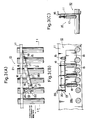
- Fig.3 (A) is a partial top plan view illustrating the apparatus of Fig.2 of the present invention.
- Fig.3 (B) is a sectional view of the apparatus taken on line 1 - 1 of Fig.3 (A) of the present invention.
- Fig.3 (C) is a sectional view of the apparatus taken on line 2 - 2 of Fig.3 (A) of the present invention.
- Guide means 14a for changing alternately directions of movements of a wire rod 13 in a state such that said wire rod is in the form of continuous series of loops to the left and to the right relative to the center line of a conveyer, that is, for moving the wire rod 13 in zigzags are alternately arranged on side walls 11 of conveyer 10 for transporting the wire rod. Positions, on which the guide means 14 are mounted, are not confined to the side walls 11 of the conveyer.
- the guide means can be mounted near the conveyer 10.
- Each of the guide means 14 comprises arm 16 for changing the directions of movements of the wire rod 13 toward the center line of the conveyer 10 and a plurality of vertical rollers 17 vertically arranged at a definite interval along the longitudinal direction of the arm 16.
- the end of the arm 16 is axially fixed on the side wall 11 of the conveyer 10 by means of axis 15 on the upstream in the direction of the movement of the wire rod.
- Blocking plates 18 are vertically fixed in a lower portion of the arm 16 to block up openings among rollers 17.
- the end of the arm 16 is fixed with stopper 19 on the downstream in the direction of the movement of the wire rod.
- a plurality of other rollers of smaller diameter than that of the vertical roller 17 can be arranged among the vertical rollers 17.
- Said stopper 19 comprises connecting member 20, whose end is axially connected to the side wall 11 of the conveyer 10, pin hole 21 formed at the end of the connecting material 20 and the arm 16 on the downstream in the direction of movement of the wire rod and pin 22 to be inseted into said pin hole 21.
- An angle formed by the arm 16 relative to the center line of the conveyer can be changed in accordance with diameters of the rings of the wire rod 13.
- the end of a motor-driven cylinder can be axially fixed at the end of the arm 16 on the downstream in the direction of movement of the wire rod.
- the wire rod 13 is transported in the following way:
- Arm 16 is arranged toward the center line of the conveyer in accordance with a diameter of the wire rod 13 with axis 15 as the center. Then, the arm 16 is fixed in a predetermined position by means of pin 12 of stopper 19.
- the wire rod 13 moving on the conveyer 10 is smoothly and continuously pushed in toward the center line of the conveyer 10 by means of the vertical rollers 17. Since the wire rod is transported on the conveyer 10, moving in a continuous zigzag in this way, the portions of the wire rod 13 where the rings of the wire rod overlap each other change constantly. Accordingly, the wire rod 13 is uniformly cooled. Further, since openings among the vertical rollers 17 are blocked up with the blocking plates 18, the end of the wire rod 13 cannot be caught by the openings among the vertical rollers 17.
- a further quide means 14b is shown in Figs. (A) to (C).
- the quide means 14b comprises arm 16 arranged toward the center line of the conveyer 10 in the upper portion of the conveyer 10 and rotating belt 23 mounted in the lower portion of said arm 16 along said arm 16.
- the rotating belt 23 is mounted endlessly among pulleys 24 vertically mounted on the arm 16.
- a chain can be used instead of the rotating belt 23.
- the quide means has member 19 connecting the arm 16 to the side wall of the conveyer 10, pin holes 21 made in the member 19 to change angles of the guide means relative to the direction along the center line of the conveyer and pin 22 to be inserted into the pin holes made at the end of the arm.
- the guide means 14c comprises a plurality of vertical rollers 25 of different diameters vertically arranged in the upper portion of the side of the conveyer 10 at a definite interval along said conveyer.
- the diameter of said vertical roller grows large as the wire rod goes downstream in the direction of movement of the wire rod.
- the guide means 14d comprises two pieces of first pulleys 27a and 27b vertically arranged in the upper portion of the side of said conveyer at a definite interval along said conveyer, second pulley 27c arranged, being shifted from the side of the conveyer toward the center line of the conveyer, and rotating belt 28 endlessly arranged between the first pulley and the second pulley.
- the side of feed belt 28a of the rotating belt 28 comes near the center line of the conveyer 10 as the wire rod goes downstream in the direction of movement of the wire rod.
- Fig .7 shows a further apparatus for transporting hot-rolled wire rod of the present invention.
- This apparatus comprises conveyer 10 for transporting a hot-rolled wire rod in a state such that said wire rod is in the form of continuous series of loops, side walls 30 arranged in zigzags, facing each other, to have the wire rod move in zigzags with the center line of said conveyer as the center and guide members 29 arranged on the side walls 30 arranged toward the center line of the conveyer 10.
- Said side wall 30 comprises side walls arranged toward the center line of the conveyer 10 and in the direction of movement of the wire rod and side walls arranged away from the center line of the conveyer.
- the vertical rollers or the rotating belt are used as the guide members 29.
- the vertical rollers or the rotating belt which are rotated by a transporting force of the wire rod can be used.
- the vertical rollers or the rotating belt can be rotated by the use of an electrical motor.
- the wire rod can be uniformly cooled by spirally forming grooves on the vertical rollers or the rotating belt, then putting the wire rod into the grooves and suspending the wire rod. Further, when the side walls of the conveyer, on which the guide means are mounted, are made movable in the direction of the width of the conveyer by means of cylinder or the like, the guide means can be easily inspected and maintained.
- Air-blast and mist were used as cooling medium.
- a rate of the air-blast was 20 m/min.
- a mixture of water and air produced by mixing water with air by the use of sprays at a rate of 30 m3/hr for wire rod of 5.5 mm in diameter and at a rate of 60 m3/hr for wire rod of 11 mm in diameter was used.
- a ring diameter of the wire rod was 1050 mm.
- Tensile stregth test was conducted on 4 rings of the wire rod, each of which was divided into 12 equal parts.
- Nos.1 and 5 designate wire rod having been subjected to ordinary air-blast cooling without zigzag movement of the wire rod.
- Nos.3 and 7 designate wire rod having been subjected to mist cooling without zigzag movement of the wire rod.
- Nos.2, 4, 6 and 8 show wire rod having been cooled by the use of the method of the present invention.
- deviation (R) of tensile strength and drawability of the wire rod cooled by the use of the method of the present invention decreases to half of that of tensile strength and drawability of the wire rod cooled without moving in zigzags.
- standard deviation ( ⁇ ) of the tensile strength and drawability of the wire rod is small and the wire rod is uniformly cooled.
- Fig.8 there is shown a distribution of hardnesses of wire rod of 12 mm in diameter having a composition as shown in Table 1 at the end of the conveyer when the wire 2od was cooled at a rate of 20 °C/sec.
- Fig.8 (A) shows a case when the wire rod was not moved in zigzags
- Fig.8 (B) a case when the wire rod was moved in zigzags according to the present invention.
- any deviation of the hardnesses of the wire rod are not seen and it is understood that the wire rod was uniformly cooled.
- Fig.9 the relation between push-in length and tensile strength of the wire rod of 9 mm in diameter having a composition as shown in Table 1 is shown.
- Table 1 the composition as shown in Table 1 is shown.
- the push-in length of the wire rod was zero, deviation of 16 kgf/mm2 in the tensile strength occurred while deviation of the tensile strengths decreased to approximately 7 kgf/mm2 when the wire rod was pushed in by 3d/100 ( about 32 mm ) and moved in zigzags.
- An optimum push-in length of the wire rod is 80 mm. Even though the wire rod is pushed in by 30d/100, there is no change in effectiveness of cooling of the wire rod. However, when the push-in length of the wire rod exceeds 30d/100, it is expected that the deviation of tensile strength increases because ring pitches of the wire rod become small due to an increase of resistance of the wire rod in transportation.
Landscapes
- Engineering & Computer Science (AREA)
- Chemical & Material Sciences (AREA)
- Mechanical Engineering (AREA)
- Physics & Mathematics (AREA)
- Thermal Sciences (AREA)
- Crystallography & Structural Chemistry (AREA)
- Materials Engineering (AREA)
- Metallurgy (AREA)
- Organic Chemistry (AREA)
- Heat Treatment Of Strip Materials And Filament Materials (AREA)
- Forwarding And Storing Of Filamentary Material (AREA)
Applications Claiming Priority (2)
| Application Number | Priority Date | Filing Date | Title |
|---|---|---|---|
| JP3965389 | 1989-02-20 | ||
| JP39653/89 | 1989-02-20 |
Publications (2)
| Publication Number | Publication Date |
|---|---|
| EP0384010A1 true EP0384010A1 (de) | 1990-08-29 |
| EP0384010B1 EP0384010B1 (de) | 1993-07-28 |
Family
ID=12559044
Family Applications (1)
| Application Number | Title | Priority Date | Filing Date |
|---|---|---|---|
| EP89121075A Expired - Lifetime EP0384010B1 (de) | 1989-02-20 | 1989-11-14 | Verfahren zum Fördern von warmgewalztem Draht und Vorrichtung dafür |
Country Status (6)
| Country | Link |
|---|---|
| US (1) | US5052124A (de) |
| EP (1) | EP0384010B1 (de) |
| JP (1) | JPH02305927A (de) |
| KR (1) | KR920004666B1 (de) |
| BR (1) | BR9000763A (de) |
| DE (1) | DE68907888T2 (de) |
Cited By (2)
| Publication number | Priority date | Publication date | Assignee | Title |
|---|---|---|---|---|
| EP0974407A3 (de) * | 1998-07-21 | 2002-03-20 | Morgan Construction Company | Vorrichtung zum Zentrieren von Drahtwindungen auf einem Kühlförderer |
| EP4186605A4 (de) * | 2021-04-28 | 2024-06-12 | Zenith Steel Group Co., Ltd. | Kühlrollenbahn zur verbesserung der kühlgleichmässigkeit einer spinnspule und verwendungsverfahren |
Families Citing this family (2)
| Publication number | Priority date | Publication date | Assignee | Title |
|---|---|---|---|---|
| KR100863743B1 (ko) * | 2002-08-30 | 2008-10-16 | 주식회사 포스코 | 선재 권취기의 선재코일 겹침 밀도 조정장치 |
| JP6466154B2 (ja) * | 2014-12-10 | 2019-02-06 | 高周波熱錬株式会社 | 熱処理装置 |
Citations (8)
| Publication number | Priority date | Publication date | Assignee | Title |
|---|---|---|---|---|
| DD28201A (de) * | ||||
| DE953244C (de) * | 1954-01-19 | 1956-11-29 | Sundwiger Eisen Maschinen | Bandfuehrung |
| DE1214635B (de) * | 1964-03-23 | 1966-04-21 | Schloemann Ag | Vorrichtung zum Kuehlen von mittel- und hoch-legiertem Walzdraht |
| AT283247B (de) * | 1966-10-14 | 1970-07-27 | Huettenwerk Oberhausen Ag | Verfahren zum Auslegen von Walzdraht |
| CH500117A (de) * | 1968-11-21 | 1970-12-15 | Sig Schweiz Industrieges | Sammelweiche in einer Transportanlage mit endlosen Förderorganen |
| DE1752025A1 (de) * | 1968-01-30 | 1970-12-23 | Schloemann Ag | Vorrichtung zur Durchfuehrung des Verfahrens zum kontinuierlichen Ablegen eines Drahtwindungsstranges auf ein endloses Foerdermittel |
| AT321232B (de) * | 1972-06-05 | 1975-03-25 | Sumitomo Metal Ind | Verfahren und Vorrichtung zum Abkühlen von heißem Draht |
| CH668052A5 (de) * | 1984-12-13 | 1988-11-30 | Seitz Enzinger Noll Masch | Gelaenderhalter fuer einen transporteur. |
Family Cites Families (6)
| Publication number | Priority date | Publication date | Assignee | Title |
|---|---|---|---|---|
| JPS5121369B2 (de) * | 1972-06-05 | 1976-07-02 | ||
| CA961314A (en) * | 1971-10-13 | 1975-01-21 | Takuo Mizoguchi | Method and apparatus for cooling wire rods |
| JPS4958839A (de) * | 1972-10-04 | 1974-06-07 | ||
| JPS4958838A (de) * | 1972-10-05 | 1974-06-07 | ||
| JPS5121369A (en) * | 1974-08-16 | 1976-02-20 | Hitachi Ltd | Sentakukino seigyokairo |
| US4168993A (en) * | 1978-08-10 | 1979-09-25 | Morgan Construction Company | Process and apparatus for sequentially forming and treating steel rod |
-
1989
- 1989-07-17 JP JP1184287A patent/JPH02305927A/ja active Pending
- 1989-10-23 US US07/426,891 patent/US5052124A/en not_active Expired - Fee Related
- 1989-11-14 DE DE89121075T patent/DE68907888T2/de not_active Expired - Fee Related
- 1989-11-14 EP EP89121075A patent/EP0384010B1/de not_active Expired - Lifetime
- 1989-12-06 KR KR1019890018039A patent/KR920004666B1/ko not_active Expired
-
1990
- 1990-02-19 BR BR909000763A patent/BR9000763A/pt not_active IP Right Cessation
Patent Citations (8)
| Publication number | Priority date | Publication date | Assignee | Title |
|---|---|---|---|---|
| DD28201A (de) * | ||||
| DE953244C (de) * | 1954-01-19 | 1956-11-29 | Sundwiger Eisen Maschinen | Bandfuehrung |
| DE1214635B (de) * | 1964-03-23 | 1966-04-21 | Schloemann Ag | Vorrichtung zum Kuehlen von mittel- und hoch-legiertem Walzdraht |
| AT283247B (de) * | 1966-10-14 | 1970-07-27 | Huettenwerk Oberhausen Ag | Verfahren zum Auslegen von Walzdraht |
| DE1752025A1 (de) * | 1968-01-30 | 1970-12-23 | Schloemann Ag | Vorrichtung zur Durchfuehrung des Verfahrens zum kontinuierlichen Ablegen eines Drahtwindungsstranges auf ein endloses Foerdermittel |
| CH500117A (de) * | 1968-11-21 | 1970-12-15 | Sig Schweiz Industrieges | Sammelweiche in einer Transportanlage mit endlosen Förderorganen |
| AT321232B (de) * | 1972-06-05 | 1975-03-25 | Sumitomo Metal Ind | Verfahren und Vorrichtung zum Abkühlen von heißem Draht |
| CH668052A5 (de) * | 1984-12-13 | 1988-11-30 | Seitz Enzinger Noll Masch | Gelaenderhalter fuer einen transporteur. |
Non-Patent Citations (1)
| Title |
|---|
| Soviet Inventions Illustrated, sections P,Q, week 8725, August 8, 1987, Derwent Publications Ltd., London, P51; & SU,A,1266598 (MAME). * |
Cited By (2)
| Publication number | Priority date | Publication date | Assignee | Title |
|---|---|---|---|---|
| EP0974407A3 (de) * | 1998-07-21 | 2002-03-20 | Morgan Construction Company | Vorrichtung zum Zentrieren von Drahtwindungen auf einem Kühlförderer |
| EP4186605A4 (de) * | 2021-04-28 | 2024-06-12 | Zenith Steel Group Co., Ltd. | Kühlrollenbahn zur verbesserung der kühlgleichmässigkeit einer spinnspule und verwendungsverfahren |
Also Published As
| Publication number | Publication date |
|---|---|
| JPH02305927A (ja) | 1990-12-19 |
| US5052124A (en) | 1991-10-01 |
| KR910011358A (ko) | 1991-08-07 |
| BR9000763A (pt) | 1991-01-22 |
| DE68907888D1 (de) | 1993-09-02 |
| DE68907888T2 (de) | 1993-12-16 |
| KR920004666B1 (ko) | 1992-06-13 |
| EP0384010B1 (de) | 1993-07-28 |
Similar Documents
| Publication | Publication Date | Title |
|---|---|---|
| EP0708182A1 (de) | Hochfestes stahldrahtmaterial mithervorragendem ermuedungsverhalten und hochfester stahldraht | |
| DE69023690T2 (de) | Elastomerstreifen und Verfahren zu dessen Herstellung. | |
| DE68916603T2 (de) | Verfahren zur schnellen Direktkühlung warmgewalzter Drähte. | |
| EP0384010A1 (de) | Verfahren zum Fördern von warmgewalztem Draht und Vorrichtung dafür | |
| GB1400813A (en) | Process and apparatus for cooling hot-rolled rods | |
| EP0060732A2 (de) | Steuerbare Kühleinrichtung für Walzdraht | |
| EP1172035B1 (de) | Verfahren und Vorrichtung zur Lageänderung von Wurstketten | |
| DE4124291C2 (de) | Einrichtung zum Transport von Stückgütern, insbesondere Bauteilen | |
| WO2024025977A1 (en) | Embossed plastic strap and method of manufacture | |
| DE68909159D1 (de) | Verfahren und Anlage zur Herstellung von glattem Stahldraht mit kleinem Durchschnitt. | |
| CA1214037A (en) | Continuous annealing apparatus | |
| JPH073810U (ja) | 熱間圧延線材の蛇行搬送装置 | |
| DE102021123134B4 (de) | Förderanlage mit einem Führungskörper und Verwendung eines Führungskörpers | |
| DE69126687T2 (de) | Ofen für Rückflusslöten | |
| DE69727950T2 (de) | Anlage zum zuführen von baumstämmen zu einer vereinzeleinrichtung | |
| JPS62100316A (ja) | 瓶類の整列方法並びに装置 | |
| DE102011109534A1 (de) | Verfahren und Vorrichtung zur Kühlung von kontinuierlich durchlaufendem Material | |
| EP0161861A2 (de) | Verfahren und Vorrichtung zum Durchlaufglühen von kaltgewalzten Stahlbändern | |
| AT321232B (de) | Verfahren und Vorrichtung zum Abkühlen von heißem Draht | |
| WO1997047411A1 (de) | Stützenanordnung für dünnbandgiessen | |
| DE102006054385B4 (de) | Vorrichtung und deren Verwendung zum Ziehen oder Bremsen eines metallischen Guts | |
| JPH02112816A (ja) | 熱間圧延線材の空冷装置 | |
| EP1051269B1 (de) | Vorrichtung zum ausrichten eines bandes, insbesondere eines metallbandes | |
| DE69806077T2 (de) | Verfahren zur Erzeugung einer Resistschicht auf einer Leiterplattenbasisplatte | |
| DE8708816U1 (de) | Vorrichtung zum pneumatischen Transport |
Legal Events
| Date | Code | Title | Description |
|---|---|---|---|
| PUAI | Public reference made under article 153(3) epc to a published international application that has entered the european phase |
Free format text: ORIGINAL CODE: 0009012 |
|
| 17P | Request for examination filed |
Effective date: 19891114 |
|
| AK | Designated contracting states |
Kind code of ref document: A1 Designated state(s): DE FR GB |
|
| 17Q | First examination report despatched |
Effective date: 19920302 |
|
| GRAA | (expected) grant |
Free format text: ORIGINAL CODE: 0009210 |
|
| AK | Designated contracting states |
Kind code of ref document: B1 Designated state(s): DE FR GB |
|
| REF | Corresponds to: |
Ref document number: 68907888 Country of ref document: DE Date of ref document: 19930902 |
|
| ET | Fr: translation filed | ||
| PLBE | No opposition filed within time limit |
Free format text: ORIGINAL CODE: 0009261 |
|
| STAA | Information on the status of an ep patent application or granted ep patent |
Free format text: STATUS: NO OPPOSITION FILED WITHIN TIME LIMIT |
|
| 26N | No opposition filed | ||
| REG | Reference to a national code |
Ref country code: FR Ref legal event code: TP |
|
| REG | Reference to a national code |
Ref country code: GB Ref legal event code: 732E |
|
| PGFP | Annual fee paid to national office [announced via postgrant information from national office to epo] |
Ref country code: FR Payment date: 19991027 Year of fee payment: 11 |
|
| PGFP | Annual fee paid to national office [announced via postgrant information from national office to epo] |
Ref country code: GB Payment date: 19991104 Year of fee payment: 11 |
|
| PGFP | Annual fee paid to national office [announced via postgrant information from national office to epo] |
Ref country code: DE Payment date: 19991216 Year of fee payment: 11 |
|
| PG25 | Lapsed in a contracting state [announced via postgrant information from national office to epo] |
Ref country code: GB Free format text: LAPSE BECAUSE OF NON-PAYMENT OF DUE FEES Effective date: 20001114 |
|
| GBPC | Gb: european patent ceased through non-payment of renewal fee |
Effective date: 20001114 |
|
| PG25 | Lapsed in a contracting state [announced via postgrant information from national office to epo] |
Ref country code: FR Free format text: LAPSE BECAUSE OF NON-PAYMENT OF DUE FEES Effective date: 20010731 |
|
| PG25 | Lapsed in a contracting state [announced via postgrant information from national office to epo] |
Ref country code: DE Free format text: LAPSE BECAUSE OF NON-PAYMENT OF DUE FEES Effective date: 20010801 |
|
| REG | Reference to a national code |
Ref country code: FR Ref legal event code: ST |