EP0384032A1 - Vérin à fluide sous pression - Google Patents
Vérin à fluide sous pression Download PDFInfo
- Publication number
- EP0384032A1 EP0384032A1 EP89123620A EP89123620A EP0384032A1 EP 0384032 A1 EP0384032 A1 EP 0384032A1 EP 89123620 A EP89123620 A EP 89123620A EP 89123620 A EP89123620 A EP 89123620A EP 0384032 A1 EP0384032 A1 EP 0384032A1
- Authority
- EP
- European Patent Office
- Prior art keywords
- tension
- tension element
- pressure
- cylinder according
- working cylinder
- Prior art date
- Legal status (The legal status is an assumption and is not a legal conclusion. Google has not performed a legal analysis and makes no representation as to the accuracy of the status listed.)
- Granted
Links
- 239000004033 plastic Substances 0.000 claims description 8
- 229920003023 plastic Polymers 0.000 claims description 8
- 239000000463 material Substances 0.000 claims description 6
- 239000007769 metal material Substances 0.000 claims description 2
- 239000012530 fluid Substances 0.000 claims 1
- 238000010276 construction Methods 0.000 abstract description 2
- 230000002093 peripheral effect Effects 0.000 abstract 1
- 238000000465 moulding Methods 0.000 description 7
- 238000007789 sealing Methods 0.000 description 4
- 238000011161 development Methods 0.000 description 2
- 230000018109 developmental process Effects 0.000 description 2
- 229910000831 Steel Inorganic materials 0.000 description 1
- 229920006231 aramid fiber Polymers 0.000 description 1
- 230000015572 biosynthetic process Effects 0.000 description 1
- 238000000034 method Methods 0.000 description 1
- 229920002635 polyurethane Polymers 0.000 description 1
- 239000004814 polyurethane Substances 0.000 description 1
- 239000010959 steel Substances 0.000 description 1
Images

Classifications
-
- F—MECHANICAL ENGINEERING; LIGHTING; HEATING; WEAPONS; BLASTING
- F15—FLUID-PRESSURE ACTUATORS; HYDRAULICS OR PNEUMATICS IN GENERAL
- F15B—SYSTEMS ACTING BY MEANS OF FLUIDS IN GENERAL; FLUID-PRESSURE ACTUATORS, e.g. SERVOMOTORS; DETAILS OF FLUID-PRESSURE SYSTEMS, NOT OTHERWISE PROVIDED FOR
- F15B15/00—Fluid-actuated devices for displacing a member from one position to another; Gearing associated therewith
- F15B15/08—Characterised by the construction of the motor unit
- F15B15/084—Characterised by the construction of the motor unit the motor being of the rodless piston type, e.g. with cable, belt or chain
-
- Y—GENERAL TAGGING OF NEW TECHNOLOGICAL DEVELOPMENTS; GENERAL TAGGING OF CROSS-SECTIONAL TECHNOLOGIES SPANNING OVER SEVERAL SECTIONS OF THE IPC; TECHNICAL SUBJECTS COVERED BY FORMER USPC CROSS-REFERENCE ART COLLECTIONS [XRACs] AND DIGESTS
- Y10—TECHNICAL SUBJECTS COVERED BY FORMER USPC
- Y10T—TECHNICAL SUBJECTS COVERED BY FORMER US CLASSIFICATION
- Y10T74/00—Machine element or mechanism
- Y10T74/18—Mechanical movements
- Y10T74/18568—Reciprocating or oscillating to or from alternating rotary
- Y10T74/18832—Reciprocating or oscillating to or from alternating rotary including flexible drive connector [e.g., belt, chain, strand, etc.]
- Y10T74/18848—Reciprocating or oscillating to or from alternating rotary including flexible drive connector [e.g., belt, chain, strand, etc.] with pulley
-
- Y—GENERAL TAGGING OF NEW TECHNOLOGICAL DEVELOPMENTS; GENERAL TAGGING OF CROSS-SECTIONAL TECHNOLOGIES SPANNING OVER SEVERAL SECTIONS OF THE IPC; TECHNICAL SUBJECTS COVERED BY FORMER USPC CROSS-REFERENCE ART COLLECTIONS [XRACs] AND DIGESTS
- Y10—TECHNICAL SUBJECTS COVERED BY FORMER USPC
- Y10T—TECHNICAL SUBJECTS COVERED BY FORMER US CLASSIFICATION
- Y10T74/00—Machine element or mechanism
- Y10T74/20—Control lever and linkage systems
- Y10T74/20396—Hand operated
- Y10T74/20402—Flexible transmitter [e.g., Bowden cable]
- Y10T74/20456—Specific cable or sheath structure
Definitions
- the invention relates to a pressure-actuated working cylinder according to the preamble of patent claim 1.
- Such a cylinder is known from DE-OS 24 04 244.
- This known working cylinder has a cylinder tube in which a piston with a circular cross section is arranged so as to be displaceable and sealed.
- a tension element which is designed as a flat strip, is fastened to the end faces of the piston facing away from one another. The traction element is sealed out of the facing end faces of the cylinder tube.
- a guide for a driver is provided on the lateral surface of the cylinder in the direction of the longitudinal axis of the cylinder.
- the driver is connected to the tension element, the tension element being guided over deflection elements arranged on the cylinder faces.
- the driver is also moved in the direction of the longitudinal axis of the cylinder by means of the tension element.
- This known working cylinder has the disadvantage that, owing to the cross-sectional shape of the piston, it is relatively high in its construction and, due to the cross-sectional shape of the tension element, cannot be sealed absolutely reliably in the area of the bushings for the tension element.
- the invention has for its object to provide a pressure-actuated working cylinder of the type mentioned, which is compact in structure and ensures a secure seal of the bushing for the tension element.
- the invention offers in particular the advantage of obtaining a working cylinder which is very flat and whose implementation for the tension element can be sealed very well with simple means. Because the tension element has a cross section with a continuous circumferential line that deviates from the circular shape, small rollers can be used as deflection elements. If the tensile element, as specified in the subclaims, is composed of several tensile strands, preferably consisting of a plastic, a particularly high tensile strength of the tensile element is achieved.
- the tensile cord or the tensile cords is or are surrounded by a jacket made of a plastic material, and the tension element formed from the tensile cord or the tensile cords and the jacket has the cross-sectional shape mentioned above, the combination achieved by high tensile strength of the tensile element and good sealability of the bushings for the tensile element in the end walls of the cylinder.
- FIG. 1 shows a cylinder tube (10) consisting of a profile tube, which is closed on both ends by a first cover (1) and a second cover (15).
- a piston (11) is arranged in the cylinder (10) in a sealed, displaceable manner by means of sealing rings (27, 32) mounted in circumferential grooves (28, 33) of the piston (11).
- the piston (11) divides the cylinder (10) into a first working chamber (40) and a second working chamber (24, 17) opposite the first working chamber (40) on the other side of the piston (11).
- the end walls of the cylinder (10) are formed from the covers (1) and (15).
- the first working chamber (40) can optionally be connected to a pressure medium source or to the atmosphere or to a return via a first pressure medium connection (41) and a valve device (not shown).
- the second working chamber (24, 17) via a pressure medium connection (16) and Valve device can be connected either to the pressure medium source or to the atmosphere or to the return.
- the first cover (1) has on its side facing the cylinder tube (10), in the area adjoining the cylinder tube (10), a circumferential groove (34) in which a groove ring (35) is mounted.
- the second cover (15) on its side facing the cylinder tube (10), in the area adjoining the cylinder tube (10), has a circumferential groove (22) in which a groove ring (23) is mounted.
- a tubular projection (36) is provided inside the first cover (1) and extends in the direction of the first working chamber (40) of the cylinder.
- a tubular molding (18) is provided within the second cover (15), which extends in the direction of the second working chamber (24, 17).
- a first roller (2) serving as a deflection element is rotatably mounted in the first cover (1) on an axis (3) arranged transversely to the longitudinal axis of the cylinder tube (10).
- a second cover (15) on the side of the tubular molding (18) of the second cover (15) facing away from the second working chamber (24, 17), there is also an axis (13) arranged as a deflecting element, transverse to the longitudinal axis of the cylinder tube (10) serving second roller (12) rotatably mounted.
- the free interior of the tubular molding (36) of the first cover (1) and the free interior of the tubular molding (18) of the second cover (15) serve as a first channel (39) and as a second channel (19) through which a tension element (6) is passed through.
- the pulling element (6) is fastened with its one end (30) on one side of the piston (11) in a holder (31) provided in the piston (11).
- the traction element (6) is guided through the channel (39) in the first cover (1), and the first roller (2) is partially wrapped around it, through a further channel-like recess (4) in the first cover (1) from the first cover (1) led out and runs parallel to the outer surface of the cylinder tube (10) to the second cover (15).
- the tension element (6) dips into a channel-like recess (14) in the second cover (15), partially wraps around the second roller (12), emerges from the second channel (19) of the second cover (15) and is with its other End (29) attached to a holder (26) of the piston (11) on the side of the piston (11) which faces the second cover (15).
- the space for the roller (2) and the second channel (4) in the first cover (1) is in one in the inner wall of the tubular molding (36) of the first cover (1) provided circumferential groove (37) a sealing ring (38) designed as a groove ring is mounted, which sealingly surrounds the tension element (6) at this point.
- the profile tube has a guide (5) for a driver (8, 9) running in the direction of the longitudinal axis of the cylinder.
- the driver (8) is connected to the tension element (6) in such a way that when the piston (11) is moved, the driver (8, 9) is moved in the longitudinal direction of the cylinder by means of the tension element (6).
- the piston (11) has a pot-shaped recess (7) or (25) on each of its two ends, which cooperate with the tubular projections (36) or (18) in such a way that in the respective end position of the piston ( 11) the corresponding tubular formation (36) or (18) is immersed in the associated recess (7) or (25) of the piston (11).
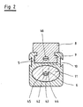
- Fig.2 the cylinder made from a profile tube with driver is shown in section.
- the cylinder has an oval-shaped cylinder bore in which the likewise oval piston (11) is slidably arranged.
- the piston (11) can of course also have any other cross-sectional shape, such as an elliptical or a circular cross-sectional shape.
- the likewise oval-shaped tension element (6) is fastened in the area of the longitudinal axis of the piston (11).
- the tension element (6) is composed of three tension strands (42, 43, 44) arranged side by side, which are enclosed by an oval jacket (45) common to all tension strands (42, 43, 44).
- the jacket (46) can e.g. are made of plastic. Of course, more than three pull strands can also be provided.
- a single flat ribbon-like tensile strand can be provided, which is surrounded by an oval jacket.
- the flat ribbon-like tension cord can be provided with elevations, depressions or perforations in order to prevent the tension cord and casing from being displaced relative to one another. If, for example, openings are provided, the material of the jacket can pass through the openings during the sheathing process, web-like connecting pieces being formed between the jacket part on one side of the tension cord and the jacket part on the side of the tension cord facing away from this side.
- the piston (11) and also the tension element (6) are arranged in the tubular body (10) in such a way that the plane of their largest diameter is essentially parallel to the transverse axis of the guide (9) running in the direction of the longitudinal axis of the tubular body (10). for the driver (8).
- the articulation point (46) for the tension element (6) on the driver (8, 9) is provided at a location on the driver (8) which is close to the inside of the guide (5) outer lateral surface of the cylinder tube (10) is located.
- the essence of the invention can be seen in the cross-sectional shape of the tension element, the tension element having a cross-section with a continuous circumferential line deviating from the circular shape.
- the extent of the cross section transverse to the plane in which the tension element is guided should be considerably larger than in the direction perpendicular to it.
- the tensile cord or the tensile cords can consist of a metallic material, such as steel, or of a plastic, such as aramid fiber.
- the sheath surrounding the tension cord or the tension cords preferably consists of a plastic material, such as polyurethane. If a tension cord, which preferably consists of a heavy-duty plastic material, is used, then a sheathing can be dispensed with.
- a tension cord which preferably consists of a heavy-duty plastic material, is used, then a sheathing can be dispensed with.
- the fact that the piston has a cross-sectional shape that deviates from the circular shape ensures that the piston is prevented from rotating. At the same time, a flat design of the working cylinder is achieved by this measure.
- the passage cross section of the sealing elements in the through openings for the tension element is adapted to the profile of the tension element.
Landscapes
- Engineering & Computer Science (AREA)
- Physics & Mathematics (AREA)
- Fluid Mechanics (AREA)
- Mechanical Engineering (AREA)
- General Engineering & Computer Science (AREA)
- Actuator (AREA)
- Mechanical Pencils And Projecting And Retracting Systems Therefor, And Multi-System Writing Instruments (AREA)
- Chair Legs, Seat Parts, And Backrests (AREA)
- Vehicle Body Suspensions (AREA)
Priority Applications (1)
| Application Number | Priority Date | Filing Date | Title |
|---|---|---|---|
| AT89123620T ATE69861T1 (de) | 1989-02-23 | 1989-12-21 | Druckmittelbetaetigbarer arbeitszylinder. |
Applications Claiming Priority (2)
| Application Number | Priority Date | Filing Date | Title |
|---|---|---|---|
| DE3905561A DE3905561C2 (de) | 1989-02-23 | 1989-02-23 | Druckmittelbetätigbarer Arbeitszylinder |
| DE3905561 | 1989-02-23 |
Publications (3)
| Publication Number | Publication Date |
|---|---|
| EP0384032A1 true EP0384032A1 (fr) | 1990-08-29 |
| EP0384032B1 EP0384032B1 (fr) | 1991-11-27 |
| EP0384032B2 EP0384032B2 (fr) | 1996-08-21 |
Family
ID=6374736
Family Applications (1)
| Application Number | Title | Priority Date | Filing Date |
|---|---|---|---|
| EP89123620A Expired - Lifetime EP0384032B2 (fr) | 1989-02-23 | 1989-12-21 | Vérin à fluide sous pression |
Country Status (8)
| Country | Link |
|---|---|
| US (1) | US5035171A (fr) |
| EP (1) | EP0384032B2 (fr) |
| JP (1) | JPH02240405A (fr) |
| AT (1) | ATE69861T1 (fr) |
| BR (1) | BR9000924A (fr) |
| CA (1) | CA2010624A1 (fr) |
| DE (2) | DE3905561C2 (fr) |
| ES (1) | ES2029111T3 (fr) |
Cited By (4)
| Publication number | Priority date | Publication date | Assignee | Title |
|---|---|---|---|---|
| EP0492750A1 (fr) * | 1990-12-20 | 1992-07-01 | MANNESMANN Aktiengesellschaft | Cylindre profilé pour vérin sans tige |
| EP0735277A3 (fr) * | 1995-03-28 | 1996-10-09 | MANNESMANN Aktiengesellschaft | Vérin hydraulique fonctionnant au moyen de fluides |
| EP0828083A3 (fr) * | 1996-09-06 | 1998-05-06 | Deutsche Star GmbH | Unité de guidage rectiligne |
| DE4111887C2 (de) * | 1991-04-09 | 1999-10-21 | Mannesmann Ag | Abdichtung eines druckmittelbetriebenen Arbeitszylinders |
Families Citing this family (18)
| Publication number | Priority date | Publication date | Assignee | Title |
|---|---|---|---|---|
| GB2239082B (en) * | 1989-12-15 | 1993-09-08 | Roy Hutchison | Recoilless air gun |
| DE4027636C2 (de) * | 1990-08-31 | 1994-03-17 | Airtec Pneumatic Gmbh | Fluidgetriebener kolbenstangenloser Arbeitszylinder |
| DE4029721C3 (de) * | 1990-09-17 | 1997-04-03 | Mannesmann Ag | Kolbenstangenloser Zylinder |
| FR2670840B1 (fr) * | 1990-12-20 | 1993-03-19 | Diebolt Remy | Actionneur d'articulation pour la mise en óoeuvre de tous mouvements rectilignes ou rotatifs. |
| DE4139919C2 (de) * | 1991-12-04 | 1994-01-20 | Freudenberg Carl Fa | Dichtung für einen hin- und hergehenden Körper |
| DE4345288C2 (de) * | 1992-10-08 | 2000-03-09 | Ckd Corp | Stangenloser Zylinder |
| JP2549709Y2 (ja) * | 1992-11-02 | 1997-09-30 | シーケーディ株式会社 | ロッドレスシリンダ |
| SE510396C2 (sv) * | 1992-10-08 | 1999-05-17 | Ckd Corp | Kolvstångslös cylinder |
| US5303638A (en) * | 1993-02-26 | 1994-04-19 | Green Joseph H | Rodless piston and cylinder assembly for a reciprocating carriage |
| DE19636272A1 (de) * | 1996-09-06 | 1998-03-12 | Star Gmbh | Linearführungseinrichtung |
| DE19636270A1 (de) * | 1996-09-06 | 1998-03-12 | Star Gmbh | Linearführungseinheit |
| US5806439A (en) * | 1997-04-23 | 1998-09-15 | Concept Unlimited Inc. | Transport system for automatic teller machines |
| US5836256A (en) * | 1997-07-02 | 1998-11-17 | Concept Unlimited Inc | Apparatus for moving automatic teller machines between retracted and extended positions |
| SE511257C2 (sv) * | 1998-01-29 | 1999-09-06 | Vbg Prod Ab | Manöveranordning |
| KR200276748Y1 (ko) * | 2001-12-07 | 2002-05-27 | 박외숙 | 환봉형 체인 로드레스 실린더 |
| DE102005029664B3 (de) * | 2005-06-21 | 2006-08-31 | Rud-Kettenfabrik Rieger & Dietz Gmbh U. Co. | Gleitschutzvorrichtung |
| DE202007004693U1 (de) * | 2007-03-30 | 2008-08-14 | Robert Bosch Gmbh | Lineareinheit |
| KR101706094B1 (ko) * | 2010-01-14 | 2017-02-14 | 삼성전자주식회사 | 로봇용 관절 구동장치 및 이를 포함하는 로봇, 로봇용 관절 구동장치의 케이블 연결방법 |
Citations (5)
| Publication number | Priority date | Publication date | Assignee | Title |
|---|---|---|---|---|
| US2524271A (en) * | 1942-08-13 | 1950-10-03 | Trico Products Corp | Piston operated locking means for servomotors |
| US3745888A (en) * | 1971-11-24 | 1973-07-17 | Gen Motors Corp | Fluid operated linear motor |
| DE2359013A1 (de) * | 1973-11-27 | 1975-05-28 | Witte & Sohn C | Kolbenzylinderaggregat |
| DE2404244A1 (de) * | 1974-01-30 | 1975-08-07 | Ahrendt & Birkendahl Ohg | Kolbenstangenloser arbeitszylinder |
| DE2938332A1 (de) * | 1979-09-21 | 1981-03-26 | Robert Bosch Gmbh, 70469 Stuttgart | Kolbenstangenloser arbeitszylinder |
Family Cites Families (12)
| Publication number | Priority date | Publication date | Assignee | Title |
|---|---|---|---|---|
| DE1293037B (de) * | 1961-08-23 | 1969-04-17 | Berlin Heinz | Durch gasfoermiges oder fluessiges Treibmittel betriebene Foerdervorrichtung zur Erzeugung von hin- und hergehenden Bewegungen von grossem Hub |
| US4052911A (en) * | 1973-05-18 | 1977-10-11 | Incom International Inc. | Cable core conduit |
| DE2519251A1 (de) * | 1975-04-30 | 1976-11-11 | Reinhold Pilzecker | Arbeitsgeraet, bestehend aus kolbenstange und zylinder |
| US4057257A (en) * | 1977-01-10 | 1977-11-08 | Tol-O-Matic, Inc. | Seal assembly |
| DE2800318A1 (de) * | 1978-01-04 | 1979-07-12 | Erhard Rilling | Pneumatische oder hydraulische zylinder/kolben-anordnung mit abtriebswelle |
| YU143979A (en) * | 1979-06-19 | 1983-01-21 | Miln Dobljekar | Cylinder with a chain |
| DE2939153C2 (de) * | 1979-09-27 | 1983-12-22 | Dürkoppwerke GmbH, 4800 Bielefeld | Strömungsmittelbetriebener Linearantrieb für ein mit großem Hub geradlinig bewegtes Abtriebsglied |
| DE3317113A1 (de) * | 1983-05-10 | 1984-11-15 | Knorr-Bremse GmbH, 8000 München | Positioniereinrichtung fuer kolbenstangenlose zylinder |
| US4683774A (en) * | 1984-03-08 | 1987-08-04 | Delta Elettronica S.R.L. | Bowden cable |
| DE3505167A1 (de) * | 1985-02-15 | 1986-08-28 | GAS Gesellschaft für Antriebs- und Steuerungstechnik mbH & Co KG, 7742 St Georgen | Linearantrieb |
| CA1260360A (fr) * | 1986-09-05 | 1989-09-26 | Alan G. Dry | Cylindre sans bielle |
| GB8621466D0 (en) * | 1986-09-05 | 1986-10-15 | Clarke D C | Fluid operable devices |
-
1989
- 1989-02-23 DE DE3905561A patent/DE3905561C2/de not_active Expired - Lifetime
- 1989-12-21 EP EP89123620A patent/EP0384032B2/fr not_active Expired - Lifetime
- 1989-12-21 DE DE8989123620T patent/DE58900502D1/de not_active Expired - Fee Related
- 1989-12-21 AT AT89123620T patent/ATE69861T1/de not_active IP Right Cessation
- 1989-12-21 ES ES198989123620T patent/ES2029111T3/es not_active Expired - Lifetime
-
1990
- 1990-01-26 JP JP2015168A patent/JPH02240405A/ja active Pending
- 1990-02-16 US US07/480,739 patent/US5035171A/en not_active Expired - Fee Related
- 1990-02-21 CA CA002010624A patent/CA2010624A1/fr not_active Abandoned
- 1990-02-23 BR BR909000924A patent/BR9000924A/pt unknown
Patent Citations (5)
| Publication number | Priority date | Publication date | Assignee | Title |
|---|---|---|---|---|
| US2524271A (en) * | 1942-08-13 | 1950-10-03 | Trico Products Corp | Piston operated locking means for servomotors |
| US3745888A (en) * | 1971-11-24 | 1973-07-17 | Gen Motors Corp | Fluid operated linear motor |
| DE2359013A1 (de) * | 1973-11-27 | 1975-05-28 | Witte & Sohn C | Kolbenzylinderaggregat |
| DE2404244A1 (de) * | 1974-01-30 | 1975-08-07 | Ahrendt & Birkendahl Ohg | Kolbenstangenloser arbeitszylinder |
| DE2938332A1 (de) * | 1979-09-21 | 1981-03-26 | Robert Bosch Gmbh, 70469 Stuttgart | Kolbenstangenloser arbeitszylinder |
Cited By (5)
| Publication number | Priority date | Publication date | Assignee | Title |
|---|---|---|---|---|
| EP0492750A1 (fr) * | 1990-12-20 | 1992-07-01 | MANNESMANN Aktiengesellschaft | Cylindre profilé pour vérin sans tige |
| DE4111887C2 (de) * | 1991-04-09 | 1999-10-21 | Mannesmann Ag | Abdichtung eines druckmittelbetriebenen Arbeitszylinders |
| EP0735277A3 (fr) * | 1995-03-28 | 1996-10-09 | MANNESMANN Aktiengesellschaft | Vérin hydraulique fonctionnant au moyen de fluides |
| EP0828083A3 (fr) * | 1996-09-06 | 1998-05-06 | Deutsche Star GmbH | Unité de guidage rectiligne |
| US5868499A (en) * | 1996-09-06 | 1999-02-09 | Deutsche Star Gmbh | Linear guiding unit |
Also Published As
| Publication number | Publication date |
|---|---|
| DE58900502D1 (de) | 1992-01-09 |
| EP0384032B1 (fr) | 1991-11-27 |
| DE3905561A1 (de) | 1990-08-30 |
| JPH02240405A (ja) | 1990-09-25 |
| EP0384032B2 (fr) | 1996-08-21 |
| CA2010624A1 (fr) | 1990-08-23 |
| ES2029111T3 (es) | 1992-07-16 |
| DE3905561C2 (de) | 1995-04-20 |
| US5035171A (en) | 1991-07-30 |
| ATE69861T1 (de) | 1991-12-15 |
| BR9000924A (pt) | 1991-02-19 |
Similar Documents
| Publication | Publication Date | Title |
|---|---|---|
| DE3905561C2 (de) | Druckmittelbetätigbarer Arbeitszylinder | |
| DE4390006C2 (de) | Schaberklinge | |
| DE68902187T2 (de) | Dichtungsanordnung fuer kolbenstangenlosen pneumatikzylinder. | |
| DE3435027A1 (de) | Kolbenstangenloser zylinder | |
| DE202014101590U1 (de) | Führungssystem für Versorgungsleitungen und Roboter mit Führungssystem | |
| EP0177693A2 (fr) | Potentiomètre | |
| DE6943958U (de) | Flexible schutzumhuellung. | |
| DE3731158A1 (de) | Kolben-zylinder-aggregat | |
| DE69701700T2 (de) | Vorrichtung zum dämpfen von schwingungen in kabeln | |
| AT391005B (de) | Mechanische loeseeinrichtung fuer einen federspeicherbremszylinder | |
| DE2706163C2 (de) | Zylinder mit einem darin beweglichen Kolben | |
| EP0853201B1 (fr) | Dispositif de réglage automatique par échelons de la longueur d'un câble dans des mécanismes de commande à distance | |
| DE1806665C3 (de) | Verfahren und Vorrichtung zum Befestigen von Muffen aus Metall an gerippten Bewehrungsstäben und nach dem Verfahren hergestellte Stoßverbindung | |
| DE3517123C2 (de) | Handhebel-Fettpresse | |
| EP0127185B1 (fr) | Transmission par câble flexible | |
| DE8916204U1 (de) | Druckmittelbetätigbarer Arbeitszylinder | |
| DE3302381A1 (de) | Schub/zug-steuerkabel und spannungssteuersysteme unter verwendung desselben | |
| DE19936462B4 (de) | Abstreifring | |
| DE3145494A1 (de) | Einrichtung zur fuehrung des kolbens eines arbeitszylinders | |
| DE4111887C2 (de) | Abdichtung eines druckmittelbetriebenen Arbeitszylinders | |
| DE3710032A1 (de) | Seilbremse fuer den antrieb einer sicherheitsgurt-rueckstrammvorrichtung | |
| EP0125505A2 (fr) | Câblé de renforcement en acier pour produits élastomères | |
| DE102004057363B4 (de) | Betätigungsvorrichtung | |
| EP0416196A1 (fr) | Dispositif d'enroulement pour un arrangement de câble | |
| DE2730408A1 (de) | Rueckfuehreinrichtung fuer den kaefig eines segmentwaelzlagers |
Legal Events
| Date | Code | Title | Description |
|---|---|---|---|
| PUAI | Public reference made under article 153(3) epc to a published international application that has entered the european phase |
Free format text: ORIGINAL CODE: 0009012 |
|
| 17P | Request for examination filed |
Effective date: 19900425 |
|
| AK | Designated contracting states |
Kind code of ref document: A1 Designated state(s): AT CH DE ES FR GB IT LI NL SE |
|
| 17Q | First examination report despatched |
Effective date: 19901221 |
|
| RAP1 | Party data changed (applicant data changed or rights of an application transferred) |
Owner name: MANNESMANN REXROTH PNEUMATIK GMBH |
|
| GRAA | (expected) grant |
Free format text: ORIGINAL CODE: 0009210 |
|
| AK | Designated contracting states |
Kind code of ref document: B1 Designated state(s): AT CH DE ES FR GB IT LI NL SE |
|
| PG25 | Lapsed in a contracting state [announced via postgrant information from national office to epo] |
Ref country code: NL Free format text: LAPSE BECAUSE OF FAILURE TO SUBMIT A TRANSLATION OF THE DESCRIPTION OR TO PAY THE FEE WITHIN THE PRESCRIBED TIME-LIMIT Effective date: 19911127 |
|
| REF | Corresponds to: |
Ref document number: 69861 Country of ref document: AT Date of ref document: 19911215 Kind code of ref document: T |
|
| REF | Corresponds to: |
Ref document number: 58900502 Country of ref document: DE Date of ref document: 19920109 |
|
| GBT | Gb: translation of ep patent filed (gb section 77(6)(a)/1977) | ||
| ITF | It: translation for a ep patent filed | ||
| ET | Fr: translation filed | ||
| REG | Reference to a national code |
Ref country code: ES Ref legal event code: FG2A Ref document number: 2029111 Country of ref document: ES Kind code of ref document: T3 |
|
| PLBI | Opposition filed |
Free format text: ORIGINAL CODE: 0009260 |
|
| 26 | Opposition filed |
Opponent name: FESTO KG Effective date: 19920729 |
|
| NLR1 | Nl: opposition has been filed with the epo |
Opponent name: FESTO KG. |
|
| EAL | Se: european patent in force in sweden |
Ref document number: 89123620.0 |
|
| PGFP | Annual fee paid to national office [announced via postgrant information from national office to epo] |
Ref country code: AT Payment date: 19951122 Year of fee payment: 7 Ref country code: NL Payment date: 19951122 Year of fee payment: 7 |
|
| PGFP | Annual fee paid to national office [announced via postgrant information from national office to epo] |
Ref country code: CH Payment date: 19951127 Year of fee payment: 7 Ref country code: SE Payment date: 19951127 Year of fee payment: 7 |
|
| PGFP | Annual fee paid to national office [announced via postgrant information from national office to epo] |
Ref country code: ES Payment date: 19951222 Year of fee payment: 7 |
|
| APAC | Appeal dossier modified |
Free format text: ORIGINAL CODE: EPIDOS NOAPO |
|
| APAC | Appeal dossier modified |
Free format text: ORIGINAL CODE: EPIDOS NOAPO |
|
| PLAW | Interlocutory decision in opposition |
Free format text: ORIGINAL CODE: EPIDOS IDOP |
|
| PUAH | Patent maintained in amended form |
Free format text: ORIGINAL CODE: 0009272 |
|
| STAA | Information on the status of an ep patent application or granted ep patent |
Free format text: STATUS: PATENT MAINTAINED AS AMENDED |
|
| 27A | Patent maintained in amended form |
Effective date: 19960821 |
|
| AK | Designated contracting states |
Kind code of ref document: B2 Designated state(s): AT CH DE ES FR GB IT LI NL SE |
|
| ET3 | Fr: translation filed ** decision concerning opposition | ||
| GBTA | Gb: translation of amended ep patent filed (gb section 77(6)(b)/1977) |
Effective date: 19891224 |
|
| REG | Reference to a national code |
Ref country code: CH Ref legal event code: AEN Free format text: AUFRECHTERHALTUNG DES PATENTES IN GEAENDERTER FORM |
|
| NLR2 | Nl: decision of opposition | ||
| ITF | It: translation for a ep patent filed | ||
| PG25 | Lapsed in a contracting state [announced via postgrant information from national office to epo] |
Ref country code: ES Free format text: LAPSE BECAUSE OF FAILURE TO SUBMIT A TRANSLATION OF THE DESCRIPTION OR TO PAY THE FEE WITHIN THE PRESCRIBED TIME-LIMIT Effective date: 19961202 |
|
| PG25 | Lapsed in a contracting state [announced via postgrant information from national office to epo] |
Ref country code: AT Effective date: 19961221 |
|
| PG25 | Lapsed in a contracting state [announced via postgrant information from national office to epo] |
Ref country code: SE Free format text: LAPSE BECAUSE OF NON-PAYMENT OF DUE FEES Effective date: 19961222 |
|
| PG25 | Lapsed in a contracting state [announced via postgrant information from national office to epo] |
Ref country code: LI Effective date: 19961231 Ref country code: CH Effective date: 19961231 |
|
| NLV1 | Nl: lapsed or annulled due to failure to fulfill the requirements of art. 29p and 29m of the patents act | ||
| REG | Reference to a national code |
Ref country code: CH Ref legal event code: PL |
|
| PGFP | Annual fee paid to national office [announced via postgrant information from national office to epo] |
Ref country code: GB Payment date: 20001115 Year of fee payment: 12 |
|
| PGFP | Annual fee paid to national office [announced via postgrant information from national office to epo] |
Ref country code: FR Payment date: 20001204 Year of fee payment: 12 |
|
| PG25 | Lapsed in a contracting state [announced via postgrant information from national office to epo] |
Ref country code: GB Free format text: LAPSE BECAUSE OF NON-PAYMENT OF DUE FEES Effective date: 20011221 |
|
| REG | Reference to a national code |
Ref country code: GB Ref legal event code: IF02 |
|
| GBPC | Gb: european patent ceased through non-payment of renewal fee |
Effective date: 20011221 |
|
| PG25 | Lapsed in a contracting state [announced via postgrant information from national office to epo] |
Ref country code: FR Free format text: LAPSE BECAUSE OF NON-PAYMENT OF DUE FEES Effective date: 20020830 |
|
| REG | Reference to a national code |
Ref country code: FR Ref legal event code: ST |
|
| APAH | Appeal reference modified |
Free format text: ORIGINAL CODE: EPIDOSCREFNO |
|
| PG25 | Lapsed in a contracting state [announced via postgrant information from national office to epo] |
Ref country code: IT Free format text: LAPSE BECAUSE OF NON-PAYMENT OF DUE FEES;WARNING: LAPSES OF ITALIAN PATENTS WITH EFFECTIVE DATE BEFORE 2007 MAY HAVE OCCURRED AT ANY TIME BEFORE 2007. THE CORRECT EFFECTIVE DATE MAY BE DIFFERENT FROM THE ONE RECORDED. Effective date: 20051221 |
|
| PGFP | Annual fee paid to national office [announced via postgrant information from national office to epo] |
Ref country code: DE Payment date: 20061218 Year of fee payment: 18 |
|
| PG25 | Lapsed in a contracting state [announced via postgrant information from national office to epo] |
Ref country code: DE Free format text: LAPSE BECAUSE OF NON-PAYMENT OF DUE FEES Effective date: 20080701 |