EP0384032B2 - Druckmittelbetätigbarer Arbeitszylinder - Google Patents
Druckmittelbetätigbarer Arbeitszylinder Download PDFInfo
- Publication number
- EP0384032B2 EP0384032B2 EP89123620A EP89123620A EP0384032B2 EP 0384032 B2 EP0384032 B2 EP 0384032B2 EP 89123620 A EP89123620 A EP 89123620A EP 89123620 A EP89123620 A EP 89123620A EP 0384032 B2 EP0384032 B2 EP 0384032B2
- Authority
- EP
- European Patent Office
- Prior art keywords
- traction
- operated
- sheath
- working cylinder
- accordance
- Prior art date
- Legal status (The legal status is an assumption and is not a legal conclusion. Google has not performed a legal analysis and makes no representation as to the accuracy of the status listed.)
- Expired - Lifetime
Links
- 230000002093 peripheral effect Effects 0.000 claims abstract 3
- 239000004033 plastic Substances 0.000 claims description 10
- 229920003023 plastic Polymers 0.000 claims description 10
- 239000000463 material Substances 0.000 claims description 5
- 239000007769 metal material Substances 0.000 claims description 2
- 230000007704 transition Effects 0.000 claims 1
- 238000010276 construction Methods 0.000 abstract description 3
- 229910000831 Steel Inorganic materials 0.000 description 15
- 239000010959 steel Substances 0.000 description 15
- 238000005452 bending Methods 0.000 description 10
- 238000007789 sealing Methods 0.000 description 8
- 230000015572 biosynthetic process Effects 0.000 description 5
- 238000005755 formation reaction Methods 0.000 description 5
- 238000011161 development Methods 0.000 description 2
- 230000018109 developmental process Effects 0.000 description 2
- 238000000034 method Methods 0.000 description 2
- 229910000639 Spring steel Inorganic materials 0.000 description 1
- 229920006231 aramid fiber Polymers 0.000 description 1
- 230000007423 decrease Effects 0.000 description 1
- 238000009434 installation Methods 0.000 description 1
- 238000000465 moulding Methods 0.000 description 1
- 229920002635 polyurethane Polymers 0.000 description 1
- 239000004814 polyurethane Substances 0.000 description 1
Images

Classifications
-
- F—MECHANICAL ENGINEERING; LIGHTING; HEATING; WEAPONS; BLASTING
- F15—FLUID-PRESSURE ACTUATORS; HYDRAULICS OR PNEUMATICS IN GENERAL
- F15B—SYSTEMS ACTING BY MEANS OF FLUIDS IN GENERAL; FLUID-PRESSURE ACTUATORS, e.g. SERVOMOTORS; DETAILS OF FLUID-PRESSURE SYSTEMS, NOT OTHERWISE PROVIDED FOR
- F15B15/00—Fluid-actuated devices for displacing a member from one position to another; Gearing associated therewith
- F15B15/08—Characterised by the construction of the motor unit
- F15B15/084—Characterised by the construction of the motor unit the motor being of the rodless piston type, e.g. with cable, belt or chain
-
- Y—GENERAL TAGGING OF NEW TECHNOLOGICAL DEVELOPMENTS; GENERAL TAGGING OF CROSS-SECTIONAL TECHNOLOGIES SPANNING OVER SEVERAL SECTIONS OF THE IPC; TECHNICAL SUBJECTS COVERED BY FORMER USPC CROSS-REFERENCE ART COLLECTIONS [XRACs] AND DIGESTS
- Y10—TECHNICAL SUBJECTS COVERED BY FORMER USPC
- Y10T—TECHNICAL SUBJECTS COVERED BY FORMER US CLASSIFICATION
- Y10T74/00—Machine element or mechanism
- Y10T74/18—Mechanical movements
- Y10T74/18568—Reciprocating or oscillating to or from alternating rotary
- Y10T74/18832—Reciprocating or oscillating to or from alternating rotary including flexible drive connector [e.g., belt, chain, strand, etc.]
- Y10T74/18848—Reciprocating or oscillating to or from alternating rotary including flexible drive connector [e.g., belt, chain, strand, etc.] with pulley
-
- Y—GENERAL TAGGING OF NEW TECHNOLOGICAL DEVELOPMENTS; GENERAL TAGGING OF CROSS-SECTIONAL TECHNOLOGIES SPANNING OVER SEVERAL SECTIONS OF THE IPC; TECHNICAL SUBJECTS COVERED BY FORMER USPC CROSS-REFERENCE ART COLLECTIONS [XRACs] AND DIGESTS
- Y10—TECHNICAL SUBJECTS COVERED BY FORMER USPC
- Y10T—TECHNICAL SUBJECTS COVERED BY FORMER US CLASSIFICATION
- Y10T74/00—Machine element or mechanism
- Y10T74/20—Control lever and linkage systems
- Y10T74/20396—Hand operated
- Y10T74/20402—Flexible transmitter [e.g., Bowden cable]
- Y10T74/20456—Specific cable or sheath structure
Definitions
- the invention relates to a pressure-operated cylinder according to the preamble of claim 1.
- Such a working cylinder is known from DE-A-2359013.
- the known version uses a tension element which is formed from a plastic-coated, calibrated steel cable.
- a tension element which is formed from a plastic-coated, calibrated steel cable.
- Such steel cables are subject to a high bending stress when passing through the deflection roller, so that due to the risk of breakage, the bending stress can only be achieved by a correspondingly large roller diameter.
- the larger roller diameter necessarily leads to a greater overall height of the working cylinder and is therefore unfavorable for many installation cases. It is of little use, however, that such a steel cable subjected to bending stress can be adequately sealed by the plastic sheathing and by the circular cross-sectional shape. Both the risk of breakage and the larger roller diameter required are disadvantageous.
- Working cylinders are also known which can be provided with smaller reel diameters because a steel band is used instead of the steel cable (DE-A-2404244). In the case of thin steel strips, the bending stress is reduced, but such steel strips must be sealed with lip seals.
- the lip seals cannot be kept permanently sealed against the media pressure because of the resulting cutting-like edge edges of the rectangular spring steel strip cross section.
- the thickness of the steel strip can also not be reduced arbitrarily.
- thinner steel strips are difficult to guide sideways and, on the other hand, the reduced fatigue strength decreases with the reduced thickness.
- a lateral deflection of the steel band also immediately damages the sealing lips of the seal. This means that thinner steel strips are also prone to breakage and are hardly or only temporarily sealable.
- a rectangular cross-section of the tension element is subject to the same types of stress and is therefore also prone to breakage, but the tensile and compressive stresses generated are not as high.
- a rectangular cross-section on the narrow sides can only be sealed for a short time. The narrow side edges of the rectangular cross section also destroy the sealing lips when there is little lateral movement.
- the invention has for its object to provide a pressure-actuated working cylinder of the type mentioned, which is compact in construction and has a high lifespan, while still reliably sealing the bushing for the tension element.
- the invention offers in particular the advantage of obtaining a working cylinder which is very flat and whose implementation for the tension element can be sealed very easily with simple means.
- the fact that the tension element has an oval or elliptical cross section with a continuous circumferential line deviating from the circular shape means that small rollers can be used as deflection elements.
- the tensile element as indicated in the subclaims, is composed of several tensile strands, preferably consisting of a plastic, a particularly high tensile strength of the tensile element is achieved
- the tension cord or the tension cords is or are surrounded by a jacket made of a plastic material, and the tension element formed from the tension cord or the tension cords and the jacket has the cross-sectional shape mentioned above, the combination achieved by high tensile strength of the tensile element and good sealability of the bushings for the tensile element in the covers of the cylinder.
- a cylinder 10 consisting of a profile tube, which is closed on both ends by a first cover 1 and a second cover 15.
- a piston 11 is arranged such that it can be displaced in a sealed manner by means of sealing rings 27, 32 mounted in circumferential grooves 28, 33 of the piston 11.
- the piston 11 divides the cylinder 10 into a first working chamber 40 and a second working chamber 24, 17 opposite the first working chamber 40, located on the other side of the piston 11.
- the end walls of the cylinder 10 are formed by the covers 1 and 15.
- the first working chamber 40 can be connected to a pressure medium source or to the atmosphere or to a return via a first pressure medium connection 41 and a valve device (not shown).
- the second working chamber 24, 17 can be connected to the pressure medium source or to the atmosphere or to the return via a pressure medium connection 16 and the valve device.
- the first cover 1 has on its side facing the cylinder 10, in the area adjoining the cylinder 10, a running groove 34, in which a groove ring 35 is mounted.
- the second cover 15 has a circumferential groove 22 in the region adjoining the cylinder 10, in which a groove ring 23 is mounted.
- a tubular projection 36 is provided within the first cover 1 and extends in the direction of the first working chamber 40 of the cylinder 10.
- a tubular molding 18 is provided within the second cover 15, which extends in the direction of the second working chamber 24, 17.
- a first roller 2 serving as a deflection element is rotatably mounted in the first cover 1 on an axis 3 arranged transversely to the longitudinal axis of the cylinder 10.
- the second cover 15 is on the second working chamber 24, 17 facing away from the tubular projection 18 of the second cover 15, also on an axis 13 arranged transversely to the longitudinal axis of the cylinder 10, a second roller 12 serving as a deflecting element is rotatably mounted.
- the free interior of the tubular formation 36 of the first cover 1 and the free interior of the tubular formation 18 of the second cover 15 serve as a first channel 39 and as a second channel 19, through which a tension element 6 is passed.
- the traction element 6 is fastened with its one end 30 on one side of the piston 11 in a holder 31 provided in the piston 11.
- the traction element 6 is guided through the channel 39 in the first cover 1, partially wraps around the first roller 2 and is replaced by a further one channel-like recess 4 in the first cover 1 led out of the first cover 1 and runs parallel to the outer lateral surface of the cylinder 10 towards the second cover 15.
- the tension element 6 dips into a channel-like recess 14 of the second cover 15, partially wraps around the second roller 12, emerges from the second channel 19 of the second cover 15 and is at the other end 29 on a holder 26 of the piston 11 on the side attached to the piston 11, which faces the second cover 15.
- a circumferential groove 37 is provided in the inner wall of the tubular projection 36 of the first cover 1 a sealing ring 38 formed as a grooved ring, which sealingly surrounds the tension element 6 at this point.
- a sealing ring 21 designed as a groove ring is mounted, which sealingly encloses the tension element 6 at this point, so that no pressure medium from the second working chamber 24, 17 first channel 19, the space for the roller 12 and the second channel 14 can escape in the second cover 15.
- the profile tube In the area from which the tension element 6 emerges from the covers 1 and 15, the profile tube has a guide 5 for a power take-off 8 running in the direction of the longitudinal axis of the cylinder 10.
- the power take-off 8 is connected to the pulling element 6 such that when the piston 11 is displaced, the power take-off 8 is moved in the longitudinal direction of the cylinder 10 by means of the pulling element 6.
- the piston 11 has on each of its two end faces a pot-shaped recess 7 and 25, which cooperate with the tubular formations 36 and 18 in such a way that in the respective end position of the piston 11 the corresponding tubular formation 36 and 18 into the associated recess 7 or 25 of the piston 11 is immersed.
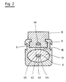
- cylinder 10 made from a profile tube with a power take-off is shown in section.
- the cylinder 10 has an oval-shaped cylinder bore in which the likewise oval piston 11 is displaceably arranged.
- the piston 11 can of course also have any other cross-sectional shape, such as e.g. an elliptical or circular cross-sectional shape.
- the tension element 6 is composed of three tension strands 42, 43 and 44 arranged side by side, which are enclosed by an oval jacket 45 common to all tension strands 42, 43, 44.
- the jacket 45 can e.g. are made of plastic. Of course, more than three pull strands can also be provided.
- a single flat band-like tensile strand can be provided, which is surrounded by an oval jacket.
- the flat ribbon-like tension cord can be provided with elevations, depressions or perforations in order to prevent the tension cord and casing from shifting relative to one another.
- Breakthroughs are provided, so the material of the sheath can pass through the perforations during the sheathing process, web-like connecting pieces being formed between the sheath part on one side of the tension cord and the sheath part on the side of the tension cord facing away from this side.
- the piston 11 and also the pulling element 6 are arranged in the cylinder 10 such that the plane of their largest diameter is essentially parallel to the transverse axis of the guide 9 for the power take-off 8 running in the direction of the longitudinal axis of the cylinder 10.
- An articulation point 46 for the tension element 6 on the power take-off 8 is provided at a point on the power take-off 8 which is located inside the guide 5 near the outer lateral surface of the cylinder 10.
- the essence of the invention can be seen in the cross-sectional shape of the tension element 6, the tension element 6 having an oval or elliptical cross-section with a continuous circumferential line deviating from the circular shape.
- the extent of the cross section transverse to the plane in which the tension element 6 is guided should be considerably larger than in the direction perpendicular thereto.
- the tension cords 42, 43, 44 can be made of a metallic material, e.g. Steel, or from a plastic, e.g. Aramid fiber.
- the sheath 45 surrounding the tension cord or the tension cords 42, 43, 44 preferably consists of a plastic material, such as e.g. Polyurethane.
- the piston 11 has a cross-sectional shape that deviates from the circular shape, an anti-rotation device for the piston 11 is achieved. At the same time, a flat construction of the working cylinder is achieved by this measure.
- the passage cross section of the sealing rings 38, 21 in the through openings for the tension element 6 is adapted to the profile of the tension element 6.
Landscapes
- Engineering & Computer Science (AREA)
- Physics & Mathematics (AREA)
- Fluid Mechanics (AREA)
- Mechanical Engineering (AREA)
- General Engineering & Computer Science (AREA)
- Actuator (AREA)
- Mechanical Pencils And Projecting And Retracting Systems Therefor, And Multi-System Writing Instruments (AREA)
- Chair Legs, Seat Parts, And Backrests (AREA)
- Vehicle Body Suspensions (AREA)
Description
- Die Erfindung betrifft einen druckmittelbetätigbaren Arbeitszylinder gemäß dem Oberbegriff des Patentanspruchs 1.
- Ein derartiger Arbeitszylinder ist aus der DE-A-2359013 bekannt.
- Die bekannte Ausführung bedient sich eines Zugelementes, das aus einem kunststoffummantelten, kalibrierten Stahlseil gebildet ist. Solche Stahlseile unterliegen beim Durchlauf um die Umlenkrolle einer hohen Biegewechselbeanspruchung, so daß wegen der Gefahr eines Bruches die Biegewechselbeanspruchung nur durch einen entsprechend großen Rollendurchmesser erreicht werden kann. Der größere Rollendurchmesser führt notwendigerweise zu einer größeren Bauhöhe des Arbeitszylinders und ist daher ungünstig für viele Einbau-Fälle. Es nutzt jedoch wenig, daß ein solches biegewechselbeanspruchtes Stahlseil durch die Kunststoffummantelung und durch die kreisförmige Querschnittsform ausreichend abgedichtet werden kann. Sowohl die Bruchgefahr als auch der notwendige größere Rollendurchmesser sind nachteilig.
- Es sind auch schon Arbeitszylinder bekannt, die mit kleineren Rollendurchmessern versehen sein können, weil anstelle des Stahlseils ein Stahlband eingesetzt wird (DE-A-2404244). Bei dünnen Stahlbändern verringert sich zwar die Biegebeanspruchung, jedoch müssen solche Stahlbänder mittels Lippendichtungen abgedichtet werden.
- Die Lippendichtungen können jedoch wegen der sich ergebenden schneidenartigen Randkanten des rechteckigen Federstahlband-Querschnitts nicht dauerhaft gegen den Mediendruck dichtgehalten werden. Die Dicke des Stahlbandes kann auch nicht beliebig verringert werden. Zum einen sind dünnere Stahlbänder schwierig seitlich zu führen und zum anderen sinkt mit der verminderten Dicke die Biegewechselbeanspruchungsfestigkeit. Eine seitliche Auslenkung des Stahlbandes beschädigt außerdem sofort die Dichtlippen der Dichtung. Somit sind dünnere Stahlbänder ebenfalls bruchgefährdet und zudem kaum oder nur vorübergehend abdichtbar. Eine fehlende Abdichtungsmöglichkeit gegen höhere Drücke, wie z.B. 10 bar, macht jedoch einen solchen druckmittelbetätigten Arbeitszylinder unbrauchbar.
- Es ist außerdem auch nicht möglich, als Ersatz eines Seiles ein Stahlband mit Sandwich-Aufbau Stahl/Kunststoff/Stahl vorzusehen, um die Probleme der Biegewechselbeanspruchung in Verbindung mit kleinen Rollendurchmessern zu beseitigen. Sämtliche dieser bekannten Zugelemente, ob mit Rechteckquerschnitt oder mit Kreisquerschnitt unterliegen der Biegung und der Rückbiegung beim Durchlauf um die Umlenkrolle. Hierbei wird die Biegung um so stärker, je kleiner der Biegeradius ist. Eine kleine Rolle bewirkt also wegen der stärkeren Krümmung eine größere Biegebeanspruchung des kreisrunden oder des rechteckigen Querschnitts. So kommt es beim Kreisquerschnitt ebenfalls während eines Umlenkvorgangs im radial inneren Querschnittsbereich zu Druckspannungen und im radial äußeren Querschnittsbereich zu Zugspannungen mit einem jeweiligen Verlauf von Null in der Mitte des Querschnitts bis zu einem Maximum (Zug/Druck) an der Außenseite. Diese Zug- und Druckspannungen verursachen je nach der Zahl der Lastwechselbeanspruchungen Brüche, da gerade das Hin- und Herbewegen des Kolbens bei entsprechenden Geschwindigkeiten die Biegewechselbeanspruchung überlagert. Währenddem also ein Kreisquerschnitt des Zugelementes sehr wohl abgedichtet werden kann, ist ein solcher Kreisquerschnitt nicht ausreichend biegewechselfestigkeitsbeständig.
- Ein Rechteckquerschnitt des Zugelementes unterliegt zwar denselben Beanspruchungsarten und ist daher ebenfalls bruchgefährdet, jedoch sind die entstehenden Zug- und Druckspannungen nicht so hoch. Andererseits ist ein Rechteckquerschnitt an den Schmalseiten nur kurzfristig brauchbar abzudichten. Die Schmalseitenkanten des Rechteckquerschnitts zerstören außerdem bei geringen Seitenbewegungen die Dichtlippen.
- Der Erfindung liegt die Aufgabe zugrunde, einen druckmittelbetätigbaren Arbeitszylinder der eingangs erwähnten Art zu schaffen, der kompakt im Aufbau ist und eine hohe Lebensdaner aufweist, bei weiterhin sicherer Abdichtung der Durchführung für das Zugelement.
- Diese Aufgabe wird mit der im Patentanspruch 1 angegebenen Erfindung gelöst. Weiterbildungen und vorteilhafte Ausgestaltungen der Erfindung sind in den Unteransprüchen angegeben.
- Die Erfindung bietet insbesondere den Vorteil, einen Arbeitszylinder zu erhalten, der sehr flach baut und dessen Durchführung für das Zugelement sich mit einfachen Mitteln sehr gut abdichten läßt. Dadurch, daß das Zugelement einen ovalen oder elliptischen Querschnitt mit einer stetigen, von der Kreisform abweichenden Umfangslinie aufweist, können kleine Rollen als Umlenkelemente verwendet werden. Wenn sich das Zugelement, wie in den Unteransprüche angegeben ist, aus mehreren vorzugsweise aus einem Kuststoff bestehenden Zugsträngen zusammensetzt, wird eine besonders hohe Zugfestigkeit des Zugelementes erreicht
- Dadurch, daß gemäß einer Weiterbildung des Erfindungsgegenstandes der Zugstrang oder auch die Zugstränge von einem Mantel aus einem Kunststoffmaterial umgeben ist bzw. umgeben sind, und das aus dem Zugstrang bzw. den Zugsträngen und dem Mantel gebildete Zugelement die vorstehend erwähnte Querschnittsform aufweist, wird die Kombination von hoher Zugfestigkeit des Zugelementes und guter Abdichtbarkeit der Durchführungen für das Zugelement in den Deckeln des Zylinders erzielt.
- Anhand der Zeichnung wird nachstehend ein Ausführungsbeispiel der Erfindung näher erläutert. Es zeigen :
- Fig. 1 einen aus einem Profilrohr gefertigten Arbeitszylinder, wobei das Profilrohr an seinen beiden Stirnseiten von je einem eine Umlenkrolle enthaltenden Deckel verschlossen ist und
- Fig. 2 das Profilrohr gemäß Fig.l im Schnitt nach der Linie A-A.
- In Fig. 1 ist ein aus einem Profilrohr bestehender Zylinder 10 dargestellt, welcher an seinen beiden Stirnseiten von einem ersten Deckel 1 und einem zweiten Deckel 15 verschlossen wird.
- Im Zylinder 10 ist ein Kolben 11 mittels in umlaufenden Nuten 28, 33 des Kolbens 11 gelagerter Dichtringe 27, 32 abgedichtet verschiebbar angeordnet.
- Der Kolben 11 unterteilt den Zylinder 10 in eine erste Arbeitskammer 40 und eine der ersten Arbeitskammer 40 gegenüber, auf der anderen Seite des Kolbens 11 gelegene zweite Arbeitskammer 24, 17. Von den Deckeln 1 und 15 werden die Stirnwände des Zylinders 10 gebildet.
- Die erste Arbeitskammer 40 ist über einen ersten Druckmittelanschluß 41 und eine nicht dargestellte Ventileinrichtung wahlweise mit einer Druckmittelquelle oder mit der Atmosphäre bzw. mit einem Rücklauf verbindbar. Desgleichen ist die zweite Arbeitskammer 24, 17 über einen Druckmittelanschluß 16 und die Ventileinrichtung wahlweise mit der Druckmittelquelle oder mit der Atmosphäre bzw. mit dem Rücklauf verbindbar.
- Der erste Deckel 1 weist auf seiner dem Zylinder 10 zugewandten Seite, in dem an den Zylinder 10 anschließenden Bereich eine anlaufende Nut 34 auf, in welcher ein Nutring 35 gelagert ist. Desgleichen weist der zweite Deckel 15 auf seiner dem Zylinder 10 zugewandten Seite, in dem an den Zylinder 10 anschließenden Bereich eine umlaufende Nut 22 auf, in der ein Nutring 23 gelagert ist.
- Innerhalb des ersten Deckels 1 ist eine rohrförmige Anformung 36 vorgesehen, die sich in Richtung auf die erste Arbeitskammer 40 des Zylinders 10 zu erstreckt.
- In gleicher Weise ist innerhalb des zweiten Deckels 15 eine rohrförmige Anformung 18 vorgesehen, die sich in Richtung auf die zweite Arbeitskammer 24, 17 zu erstreckt.
- Auf der der ersten Arbeitskammer 40 abgewandten Seite der rohrförmigen Anformung 36 ist im ersten Deckel 1 auf einer quer zur Längsachse des Zylinders 10 angeordneten Achse 3 eine als Umlenkelement dienende erste Rolle 2 drehbar gelagert Im zweiten Deckel 15 ist auf der der zweiten Arbeitskammer 24, 17 abgewandten Seite der rohrförmigen Anformung 18 des zweiten Deckels 15 ebenfalls auf einer quer zur Längsachse des Zylinders 10 angeordneten Achse 13 eine als Umlenkelement dienende zweite Rolle 12 drehbar gelagert.
- Der freie Innenraum der rohrförmigen Anformung 36 des ersten Deckels 1 und der freie Innenraum der rohrförmigen Anformung 18 des zweiten Deckels 15 dienen als ein erster Kanal 39 und als ein zweiter Kanal 19, durch welche ein Zugelement 6 hindurchgeführt ist.
- Das Zugelement 6 ist mit seinem einen Ende 30 an der einen Seite des Kolbens 11 in einer im Kolben 11 vorgesehenen Halterung 31 befestigt Durch den Kanal 39 im ersten Deckel 1 ist das Zugelement 6 hindurchgeführt, umschlingt teilweise die erste Rolle 2, wird durch eine weitere kanalartige Ausnehmung 4 im ersten Deckel 1 aus dem ersten Deckel 1 herausgeführt und verläuft parallel zur äußeren Mantelfläche des Zylinders 10 zum zweiten Deckel 15 hin. Das Zugelement 6 taucht in eine kanalartige Ausnehmung 14 des zweiten Deckels 15 ein, umschlingt teilweise die zweite Rolle 12, tritt aus dem zweiten Kanal 19 des zweiten Deckels 15 aus und ist mit seinem anderen Ende 29 an einer Halterung 26 des Kolbens 11 auf der Seite des Kolbens 11 befestigt, die dem zweiten Deckel 15 zugewandt ist.
- Um zu verhindern, daß Druckmittel aus der ersten Arbeitskammer 40 durch den Kanal 39, den Raum für die Rolle 2 und die Ausnehmung 4 im ersten Deckel 1 austritt, ist in einer in der Innenwand der rohrförmigen Anformung 36 des ersten Deckels 1 vorgesehenen umlaufenden Nut 37 ein als Nutring ausgebildeter Dichtring 38 gelagert, der das Zugelement 6 an dieser Stelle dichtend umschließt.
- Desgleichen ist in einer in der Innenwand der rohrförmigen Anformung 18 des zweiten Deckels 15 vorgesehenen umlaufenden Nut 20 ein als Nutring ausgebildeter Dichtring 21 gelagert, der an dieser Stelle das Zugelement 6 dichtend umschließt, so daß aus der zweiten Arbeitskammer 24, 17 kein Druckmittel durch den ersten Kanal 19, den Raum für die Rolle 12 und den zweiten Kanal 14 im zweiten Deckel 15 entweichen kann.
- Das Profilrohr weist in dem Bereich, aus welchem das Zugelement 6 aus den Deckeln 1 und 15 austritt, eine in Richtung der Längsachse des Zylinders 10 verlaufende Führung 5 für einen Kraftabnehmer 8, auf. Der Kraftabnehmer 8 ist mit dem Zugelement 6 verbunden, derart, daß bei einer Verschiebebewegung des Kolbens 11 der Kraftabnehmer 8 mittels des Zugelementes 6 in Längsrichtung des Zylinders 10 bewegt wird.
- Der Kolben 11 weist an seinen beiden Stirnseiten je eine topfförmige Ausnehmung 7 bzw. 25 auf, welche mit den rohrförmigen Anformungen 36 bzw. 18 in der Weise zusammenwirken, daß in der jeweiligen Endlage des Kolbens 11 die entsprechende rohrförmige Anformung 36 bzw. 18 in die zugehörige Ausnehmung 7 bzw. 25 des Kolbens 11 eintaucht.
- In Fig. 2 ist der aus einem Profilrohr hergestellte Zylinder 10 mit Kraftabnehmer im Schnitt dargestellt. Der Zylinder 10 weist eine oval ausgebildete Zylinderbohrung auf, in welcher der ebenfalls ovale Kolben 11 verschiebbar angeordnet ist Der Kolben 11 kann selbstverständlich auch jede beliebige andere Querschnittsform aufweisen, wie z.B. eine elliptische oder eine kreisförmige Querschnittsform.
- Im Bereich der Längsachse des Kolbens 11 ist das ebenfalls oval ausgebildete Zugelement 6 befestigt. Das Zugelement 6 setzt sich aus drei nebeneinanderliegend angeordneten Zugsträngen 42, 43 und 44 zusammen, die von einem für alle Zugstränge 42, 43, 44 gemeinsamen ovalen Mantel 45 umschlossen sind. Der Mantel 45 kann z.B. aus Kunststoff bestehen. Selbstverständlich können auch mehr als drei Zugstränge vorgesehen werden.
- Anstelle von mehreren Zugsträngen kann auch ein einziger flachbandartiger Zugstrang vorgesehen werden, der von einem ovalen Mantel umgeben ist.
- Der flachbandartige Zugstrang kann mit Erhöhungen, Vertiefungen oder Durchbrechungen versehen werden, um ein Verschieben von Zugstrang und Mantel gegeneinander zu verhindern.
- Werden z.B. Durchbrechungen vorgesehen, so kann das Material des Mantels beim Ummantellungsvorgang durch die Durchbrechungen hindurchtreten, wobei stegartige Verbindungsstücke zwischen dem Mantelteil auf der einen Seite des Zugstranges und dem Mantelteil auf der dieser Seite abgewandten Seite des Zugstranges gelegenen Mantelteil gebildet werden.
- Der Kolben 11 und auch das Zugelement 6 sind so im Zylinder 10 angeordnet, daß die Ebene ihres größten Durchmessers im wesentlichen parallel zu der Querachse der in Richtung der Längsachse des Zylinders 10 verlaufenden Führung 9 für den Kraftabnehmer 8 gelegen ist.
- Ein Anlenkpunkt 46 für das Zugelement 6 am Kraftabnehmer 8 ist an einer Stelle des Kraftabnehmers 8 vorgesehen, der innerhalb der Führung 5 nahe der äußeren Mantelfläche des Zylinders 10 gelegen ist.
- Das Wesentliche der Erfindung ist in der Querschnittsforrn des Zugelementes 6 zu sehen, wobei das Zugelement 6 einen ovalen oder elliptischen Querschnitt mit einer stetigen, von der Kreisform abweichenden Umfangslinie aufweist. Die Erstreckung des Querschnittes quer zu der Ebene, in der das Zugelement 6 geführt wird, sollte wesentlich größer als in der dazu senkrechten Richtung sein.
- Die Zugstränge 42, 43, 44 können aus einem metallischen Werkstoff, wie z.B. Stahl, oder aus einem Kunststoff, wie z.B. Aramidfaser, bestehen. Der den Zugstrang oder die Zugstränge 42, 43, 44 umgebende Mantel 45 besteht vorzugsweise aus einem Kunststoffmaterial, wie z.B. Polyurethan.
- Dadurch, daß der Kolben 11 eine Querschnittsform aufweist, die von der Kreisform abweicht, wird eine Verdrehsicherung für den Kolben 11 erreicht. Gleichzeitig wird durch diese Maßnahme eine flache Bauweise des Arbeitszylinders erzielt.
- Selbstverständlich ist der Durchlaßquerschnitt der Dichtringe 38, 21 in den Durchgangsöffnungen für das Zugelement 6 an das Profil des Zugelementes 6 angepaßt.
Claims (8)
- Druckmittelbetätigbarer Arbeitszylinder mit einem von einem Kolben (11) durch ein biegsames, über Rollen (2, 12) geführtes Zugelement (6) angetriebenen Kraftabnehmer (8) mit folgenden Merkmalen :a) das Zugelement (6) ist abgedichtet durch die Deckel (1, 15) des Zylinders (10) geführt ;b) innerhalb der Querschnittsform des Zugelementes (6) ist zumindest ein Zugstrang (42 ; 43 ; 44) angeordnet, der von einem Mantel (45) umgeben ist,c) der Kraftabnehmer (8) ist in einer Führung (9) in Längsrichtung des Zylinders (10) parallel geführt ;dadurch gekennzeichnet, daß das Zugelement (6) einen ovalen oder elliptischen Querschnitt mit einer stetigen, von der Kreisform abweichenden Umfangslinie mit weichen, gerundeten Übergängen, aufweist, wobei die Erstreckung des Querschnittes quer zu der Ebene, in der das Zugelement (6) geführt wird, wesentlich größer ist als in der dazu senkrechten Richtung.
- Druckmittelbetätigbarer Arbeitszylinder nach Anspruch 1, dadurch gekennzeichnet, daß sich das Zugelement (6) aus mehreren Zugsträngen (42, 43, 44) zusammensetzt, die von einem diese Zugstränge (42, 43, 44) umgebenden, für alle Zugstränge (42, 43, 44) gemeinsamen Mantel (45) umschlossen sind.
- Druckmittelbetätigbarer Arbeitszylinder nach Anspruche 1 dadurch gekennzeichnet, daß das Zugelement (6) aus einem bandförmigen Zugstrang besteht, der von dem Mantel (45) umgeben ist.
- Druckmittelbetätigbarer Arbeitszylinder nach Anspruch 3, dadurch gekennzeichnet, daß der bandförmige Zugstrang Erhöhungen oder/und Vertiefungen aufweist, welche eine Relativbewegung zwischen dem Mantel und dem Zugstrang verhindern.
- Druckmittelbetätigbarer Arbeitszylinder nach Anspruch 3, gekennzeichnet durch die folgenden Merkmale :a) der Zugstrang weist Durchbrechungen auf ;b) durch die Durchbrechungen treten stegartige Teile des Mantels (45) hindurch, welche den auf der einen Seite des Zugstranges gelegenen Teil des Mantels (45) mit dem auf der dieser Seite abgewandten Seite des Zugstranges gelegenen Teil des Mantels (45) verbinden.
- Druckmittelbetätigbarer Arbeitszylinder nach einem oder mehreren der Anspruche 1 bis 5, dadurch gekennzeichnet, daß der Zugstrang bzw. die Zugstränge (42, 43, 44) aus einem metallischen Werkstoff und der Mantel (45) aus einem Kunststoffmaterial bestehen.
- Druckmittelbetätigbarer Arbeitszylinder nach einem oder mehreren der Ansprüche 1 bis 5, dadurch gekennzeichnet, daß der Zugstrang bzw. die Zugstränge (42, 43, 44) aus einem Kunststoffmaterial bestehen.
- Druckmittelbetätigbarer Arbeitszylinder nach einem oder mehreren der Ansprüche 1 bis 7, dadurch gekennzeichnet, daß der Kolben (11) und wenigstens der den Kolben (11) führende Bereich des Innenraumes des Zylinders (10) einen Querschnitt mit einer stetigen, von der Kreisform abweichenden Umfangslinie aufweisen.
Priority Applications (1)
| Application Number | Priority Date | Filing Date | Title |
|---|---|---|---|
| AT89123620T ATE69861T1 (de) | 1989-02-23 | 1989-12-21 | Druckmittelbetaetigbarer arbeitszylinder. |
Applications Claiming Priority (2)
| Application Number | Priority Date | Filing Date | Title |
|---|---|---|---|
| DE3905561 | 1989-02-23 | ||
| DE3905561A DE3905561C2 (de) | 1989-02-23 | 1989-02-23 | Druckmittelbetätigbarer Arbeitszylinder |
Publications (3)
| Publication Number | Publication Date |
|---|---|
| EP0384032A1 EP0384032A1 (de) | 1990-08-29 |
| EP0384032B1 EP0384032B1 (de) | 1991-11-27 |
| EP0384032B2 true EP0384032B2 (de) | 1996-08-21 |
Family
ID=6374736
Family Applications (1)
| Application Number | Title | Priority Date | Filing Date |
|---|---|---|---|
| EP89123620A Expired - Lifetime EP0384032B2 (de) | 1989-02-23 | 1989-12-21 | Druckmittelbetätigbarer Arbeitszylinder |
Country Status (8)
| Country | Link |
|---|---|
| US (1) | US5035171A (de) |
| EP (1) | EP0384032B2 (de) |
| JP (1) | JPH02240405A (de) |
| AT (1) | ATE69861T1 (de) |
| BR (1) | BR9000924A (de) |
| CA (1) | CA2010624A1 (de) |
| DE (2) | DE3905561C2 (de) |
| ES (1) | ES2029111T3 (de) |
Families Citing this family (22)
| Publication number | Priority date | Publication date | Assignee | Title |
|---|---|---|---|---|
| GB2239082B (en) * | 1989-12-15 | 1993-09-08 | Roy Hutchison | Recoilless air gun |
| DE4027636C2 (de) * | 1990-08-31 | 1994-03-17 | Airtec Pneumatic Gmbh | Fluidgetriebener kolbenstangenloser Arbeitszylinder |
| DE4029721C3 (de) * | 1990-09-17 | 1997-04-03 | Mannesmann Ag | Kolbenstangenloser Zylinder |
| FR2670840B1 (fr) * | 1990-12-20 | 1993-03-19 | Diebolt Remy | Actionneur d'articulation pour la mise en óoeuvre de tous mouvements rectilignes ou rotatifs. |
| DE4041370C2 (de) * | 1990-12-20 | 1995-06-01 | Mannesmann Ag | Profilrohr für kolbenstangenlosen Arbeitszylinder |
| DE4111887C2 (de) * | 1991-04-09 | 1999-10-21 | Mannesmann Ag | Abdichtung eines druckmittelbetriebenen Arbeitszylinders |
| DE4139919C2 (de) * | 1991-12-04 | 1994-01-20 | Freudenberg Carl Fa | Dichtung für einen hin- und hergehenden Körper |
| JP2549709Y2 (ja) * | 1992-11-02 | 1997-09-30 | シーケーディ株式会社 | ロッドレスシリンダ |
| DE4345288C2 (de) * | 1992-10-08 | 2000-03-09 | Ckd Corp | Stangenloser Zylinder |
| SE510396C2 (sv) * | 1992-10-08 | 1999-05-17 | Ckd Corp | Kolvstångslös cylinder |
| US5303638A (en) * | 1993-02-26 | 1994-04-19 | Green Joseph H | Rodless piston and cylinder assembly for a reciprocating carriage |
| EP0735277A3 (de) * | 1995-03-28 | 1996-10-09 | MANNESMANN Aktiengesellschaft | Druckmittelbetriebener Arbeitszylinder |
| DE19636272A1 (de) * | 1996-09-06 | 1998-03-12 | Star Gmbh | Linearführungseinrichtung |
| US5868499A (en) * | 1996-09-06 | 1999-02-09 | Deutsche Star Gmbh | Linear guiding unit |
| DE19636270A1 (de) * | 1996-09-06 | 1998-03-12 | Star Gmbh | Linearführungseinheit |
| US5806439A (en) * | 1997-04-23 | 1998-09-15 | Concept Unlimited Inc. | Transport system for automatic teller machines |
| US5836256A (en) * | 1997-07-02 | 1998-11-17 | Concept Unlimited Inc | Apparatus for moving automatic teller machines between retracted and extended positions |
| SE511257C2 (sv) * | 1998-01-29 | 1999-09-06 | Vbg Prod Ab | Manöveranordning |
| KR200276748Y1 (ko) * | 2001-12-07 | 2002-05-27 | 박외숙 | 환봉형 체인 로드레스 실린더 |
| DE102005029664B3 (de) * | 2005-06-21 | 2006-08-31 | Rud-Kettenfabrik Rieger & Dietz Gmbh U. Co. | Gleitschutzvorrichtung |
| DE202007004693U1 (de) * | 2007-03-30 | 2008-08-14 | Robert Bosch Gmbh | Lineareinheit |
| KR101706094B1 (ko) * | 2010-01-14 | 2017-02-14 | 삼성전자주식회사 | 로봇용 관절 구동장치 및 이를 포함하는 로봇, 로봇용 관절 구동장치의 케이블 연결방법 |
Family Cites Families (17)
| Publication number | Priority date | Publication date | Assignee | Title |
|---|---|---|---|---|
| US2524271A (en) * | 1942-08-13 | 1950-10-03 | Trico Products Corp | Piston operated locking means for servomotors |
| DE1293037B (de) * | 1961-08-23 | 1969-04-17 | Berlin Heinz | Durch gasfoermiges oder fluessiges Treibmittel betriebene Foerdervorrichtung zur Erzeugung von hin- und hergehenden Bewegungen von grossem Hub |
| US3745888A (en) * | 1971-11-24 | 1973-07-17 | Gen Motors Corp | Fluid operated linear motor |
| US4052911A (en) * | 1973-05-18 | 1977-10-11 | Incom International Inc. | Cable core conduit |
| DE2359013A1 (de) * | 1973-11-27 | 1975-05-28 | Witte & Sohn C | Kolbenzylinderaggregat |
| DE2404244A1 (de) * | 1974-01-30 | 1975-08-07 | Ahrendt & Birkendahl Ohg | Kolbenstangenloser arbeitszylinder |
| DE2519251A1 (de) * | 1975-04-30 | 1976-11-11 | Reinhold Pilzecker | Arbeitsgeraet, bestehend aus kolbenstange und zylinder |
| US4057257A (en) * | 1977-01-10 | 1977-11-08 | Tol-O-Matic, Inc. | Seal assembly |
| DE2800318A1 (de) * | 1978-01-04 | 1979-07-12 | Erhard Rilling | Pneumatische oder hydraulische zylinder/kolben-anordnung mit abtriebswelle |
| YU143979A (en) * | 1979-06-19 | 1983-01-21 | Miln Dobljekar | Cylinder with a chain |
| DE2938332A1 (de) * | 1979-09-21 | 1981-03-26 | Robert Bosch Gmbh, 70469 Stuttgart | Kolbenstangenloser arbeitszylinder |
| DE2939153C2 (de) * | 1979-09-27 | 1983-12-22 | Dürkoppwerke GmbH, 4800 Bielefeld | Strömungsmittelbetriebener Linearantrieb für ein mit großem Hub geradlinig bewegtes Abtriebsglied |
| DE3317113A1 (de) * | 1983-05-10 | 1984-11-15 | Knorr-Bremse GmbH, 8000 München | Positioniereinrichtung fuer kolbenstangenlose zylinder |
| US4683774A (en) * | 1984-03-08 | 1987-08-04 | Delta Elettronica S.R.L. | Bowden cable |
| DE3505167A1 (de) * | 1985-02-15 | 1986-08-28 | GAS Gesellschaft für Antriebs- und Steuerungstechnik mbH & Co KG, 7742 St Georgen | Linearantrieb |
| CA1260360A (en) * | 1986-09-05 | 1989-09-26 | Alan G. Dry | Rodless cylinder |
| GB8621466D0 (en) * | 1986-09-05 | 1986-10-15 | Clarke D C | Fluid operable devices |
-
1989
- 1989-02-23 DE DE3905561A patent/DE3905561C2/de not_active Expired - Lifetime
- 1989-12-21 EP EP89123620A patent/EP0384032B2/de not_active Expired - Lifetime
- 1989-12-21 AT AT89123620T patent/ATE69861T1/de not_active IP Right Cessation
- 1989-12-21 DE DE8989123620T patent/DE58900502D1/de not_active Expired - Fee Related
- 1989-12-21 ES ES198989123620T patent/ES2029111T3/es not_active Expired - Lifetime
-
1990
- 1990-01-26 JP JP2015168A patent/JPH02240405A/ja active Pending
- 1990-02-16 US US07/480,739 patent/US5035171A/en not_active Expired - Fee Related
- 1990-02-21 CA CA002010624A patent/CA2010624A1/en not_active Abandoned
- 1990-02-23 BR BR909000924A patent/BR9000924A/pt unknown
Also Published As
| Publication number | Publication date |
|---|---|
| DE58900502D1 (de) | 1992-01-09 |
| EP0384032A1 (de) | 1990-08-29 |
| JPH02240405A (ja) | 1990-09-25 |
| DE3905561C2 (de) | 1995-04-20 |
| EP0384032B1 (de) | 1991-11-27 |
| ATE69861T1 (de) | 1991-12-15 |
| US5035171A (en) | 1991-07-30 |
| CA2010624A1 (en) | 1990-08-23 |
| BR9000924A (pt) | 1991-02-19 |
| ES2029111T3 (es) | 1992-07-16 |
| DE3905561A1 (de) | 1990-08-30 |
Similar Documents
| Publication | Publication Date | Title |
|---|---|---|
| EP0384032B1 (de) | Druckmittelbetätigbarer Arbeitszylinder | |
| DE69115840T2 (de) | Segmentiertes flexibles Gehäuse | |
| DE68908610T2 (de) | Flexibles Schutzrohr. | |
| DE68902187T2 (de) | Dichtungsanordnung fuer kolbenstangenlosen pneumatikzylinder. | |
| EP0407502A1 (de) | Selbsttragendes optisches kabel. | |
| EP0307569A2 (de) | Kolben-Zylinder-Aggregat | |
| DE2505568B2 (de) | Seil zur bewehrung von gegenstaenden aus elastischen oder leicht verformbaren stoffen | |
| DE4294444C2 (de) | Verbessertes mechanisches Steuerkabelsystem | |
| DE2440124A1 (de) | Dichtungsvorrichtung | |
| DE4334681C2 (de) | Bewegungseinheit zur Erzeugung einer Linearbewegung | |
| DE102020207374A1 (de) | Gurtstraffer für einen Sicherheitsgurt eines Kraftfahrzeugs | |
| DE2706163C2 (de) | Zylinder mit einem darin beweglichen Kolben | |
| DE3626045C2 (de) | ||
| EP0260225B1 (de) | Kabelführungsvorrichtung | |
| DE8916204U1 (de) | Druckmittelbetätigbarer Arbeitszylinder | |
| DE3302381A1 (de) | Schub/zug-steuerkabel und spannungssteuersysteme unter verwendung desselben | |
| DE3909344A1 (de) | Druckmittelbetaetigbarer arbeitszylinder | |
| EP0081043A2 (de) | Kolbenstange mit Kolben | |
| EP0125505A2 (de) | Verstärkungsseil aus Stahldrähten für elastomere Erzeugnisse | |
| DE3732741A1 (de) | Druckmittel-beaufschlagter arbeitszylinder mit elastisch federnder kolbenstange und elastisch federndem kolbenband | |
| DE2710749C2 (de) | Zahnriemenantrieb | |
| DE19858890C2 (de) | Kolbenstangenloser Arbeitszylinder | |
| EP4102100B1 (de) | Verbindung | |
| DE102005008710B3 (de) | Kolbenstangenloser Schlitzzylinder mit verbessertem Dichtband | |
| DE10119358C2 (de) | Druckmittelzylinder und Montagevorrichtung zu seiner Herstellung |
Legal Events
| Date | Code | Title | Description |
|---|---|---|---|
| PUAI | Public reference made under article 153(3) epc to a published international application that has entered the european phase |
Free format text: ORIGINAL CODE: 0009012 |
|
| 17P | Request for examination filed |
Effective date: 19900425 |
|
| AK | Designated contracting states |
Kind code of ref document: A1 Designated state(s): AT CH DE ES FR GB IT LI NL SE |
|
| 17Q | First examination report despatched |
Effective date: 19901221 |
|
| RAP1 | Party data changed (applicant data changed or rights of an application transferred) |
Owner name: MANNESMANN REXROTH PNEUMATIK GMBH |
|
| GRAA | (expected) grant |
Free format text: ORIGINAL CODE: 0009210 |
|
| AK | Designated contracting states |
Kind code of ref document: B1 Designated state(s): AT CH DE ES FR GB IT LI NL SE |
|
| PG25 | Lapsed in a contracting state [announced via postgrant information from national office to epo] |
Ref country code: NL Free format text: LAPSE BECAUSE OF FAILURE TO SUBMIT A TRANSLATION OF THE DESCRIPTION OR TO PAY THE FEE WITHIN THE PRESCRIBED TIME-LIMIT Effective date: 19911127 |
|
| REF | Corresponds to: |
Ref document number: 69861 Country of ref document: AT Date of ref document: 19911215 Kind code of ref document: T |
|
| REF | Corresponds to: |
Ref document number: 58900502 Country of ref document: DE Date of ref document: 19920109 |
|
| GBT | Gb: translation of ep patent filed (gb section 77(6)(a)/1977) | ||
| ITF | It: translation for a ep patent filed | ||
| ET | Fr: translation filed | ||
| REG | Reference to a national code |
Ref country code: ES Ref legal event code: FG2A Ref document number: 2029111 Country of ref document: ES Kind code of ref document: T3 |
|
| PLBI | Opposition filed |
Free format text: ORIGINAL CODE: 0009260 |
|
| 26 | Opposition filed |
Opponent name: FESTO KG Effective date: 19920729 |
|
| NLR1 | Nl: opposition has been filed with the epo |
Opponent name: FESTO KG. |
|
| EAL | Se: european patent in force in sweden |
Ref document number: 89123620.0 |
|
| PGFP | Annual fee paid to national office [announced via postgrant information from national office to epo] |
Ref country code: AT Payment date: 19951122 Year of fee payment: 7 Ref country code: NL Payment date: 19951122 Year of fee payment: 7 |
|
| PGFP | Annual fee paid to national office [announced via postgrant information from national office to epo] |
Ref country code: CH Payment date: 19951127 Year of fee payment: 7 Ref country code: SE Payment date: 19951127 Year of fee payment: 7 |
|
| PGFP | Annual fee paid to national office [announced via postgrant information from national office to epo] |
Ref country code: ES Payment date: 19951222 Year of fee payment: 7 |
|
| APAC | Appeal dossier modified |
Free format text: ORIGINAL CODE: EPIDOS NOAPO |
|
| APAC | Appeal dossier modified |
Free format text: ORIGINAL CODE: EPIDOS NOAPO |
|
| PLAW | Interlocutory decision in opposition |
Free format text: ORIGINAL CODE: EPIDOS IDOP |
|
| PUAH | Patent maintained in amended form |
Free format text: ORIGINAL CODE: 0009272 |
|
| STAA | Information on the status of an ep patent application or granted ep patent |
Free format text: STATUS: PATENT MAINTAINED AS AMENDED |
|
| 27A | Patent maintained in amended form |
Effective date: 19960821 |
|
| AK | Designated contracting states |
Kind code of ref document: B2 Designated state(s): AT CH DE ES FR GB IT LI NL SE |
|
| ET3 | Fr: translation filed ** decision concerning opposition | ||
| GBTA | Gb: translation of amended ep patent filed (gb section 77(6)(b)/1977) |
Effective date: 19891224 |
|
| REG | Reference to a national code |
Ref country code: CH Ref legal event code: AEN Free format text: AUFRECHTERHALTUNG DES PATENTES IN GEAENDERTER FORM |
|
| NLR2 | Nl: decision of opposition | ||
| ITF | It: translation for a ep patent filed | ||
| PG25 | Lapsed in a contracting state [announced via postgrant information from national office to epo] |
Ref country code: ES Free format text: LAPSE BECAUSE OF FAILURE TO SUBMIT A TRANSLATION OF THE DESCRIPTION OR TO PAY THE FEE WITHIN THE PRESCRIBED TIME-LIMIT Effective date: 19961202 |
|
| PG25 | Lapsed in a contracting state [announced via postgrant information from national office to epo] |
Ref country code: AT Effective date: 19961221 |
|
| PG25 | Lapsed in a contracting state [announced via postgrant information from national office to epo] |
Ref country code: SE Free format text: LAPSE BECAUSE OF NON-PAYMENT OF DUE FEES Effective date: 19961222 |
|
| PG25 | Lapsed in a contracting state [announced via postgrant information from national office to epo] |
Ref country code: LI Effective date: 19961231 Ref country code: CH Effective date: 19961231 |
|
| NLV1 | Nl: lapsed or annulled due to failure to fulfill the requirements of art. 29p and 29m of the patents act | ||
| REG | Reference to a national code |
Ref country code: CH Ref legal event code: PL |
|
| PGFP | Annual fee paid to national office [announced via postgrant information from national office to epo] |
Ref country code: GB Payment date: 20001115 Year of fee payment: 12 |
|
| PGFP | Annual fee paid to national office [announced via postgrant information from national office to epo] |
Ref country code: FR Payment date: 20001204 Year of fee payment: 12 |
|
| PG25 | Lapsed in a contracting state [announced via postgrant information from national office to epo] |
Ref country code: GB Free format text: LAPSE BECAUSE OF NON-PAYMENT OF DUE FEES Effective date: 20011221 |
|
| REG | Reference to a national code |
Ref country code: GB Ref legal event code: IF02 |
|
| GBPC | Gb: european patent ceased through non-payment of renewal fee |
Effective date: 20011221 |
|
| PG25 | Lapsed in a contracting state [announced via postgrant information from national office to epo] |
Ref country code: FR Free format text: LAPSE BECAUSE OF NON-PAYMENT OF DUE FEES Effective date: 20020830 |
|
| REG | Reference to a national code |
Ref country code: FR Ref legal event code: ST |
|
| APAH | Appeal reference modified |
Free format text: ORIGINAL CODE: EPIDOSCREFNO |
|
| PG25 | Lapsed in a contracting state [announced via postgrant information from national office to epo] |
Ref country code: IT Free format text: LAPSE BECAUSE OF NON-PAYMENT OF DUE FEES;WARNING: LAPSES OF ITALIAN PATENTS WITH EFFECTIVE DATE BEFORE 2007 MAY HAVE OCCURRED AT ANY TIME BEFORE 2007. THE CORRECT EFFECTIVE DATE MAY BE DIFFERENT FROM THE ONE RECORDED. Effective date: 20051221 |
|
| PGFP | Annual fee paid to national office [announced via postgrant information from national office to epo] |
Ref country code: DE Payment date: 20061218 Year of fee payment: 18 |
|
| PG25 | Lapsed in a contracting state [announced via postgrant information from national office to epo] |
Ref country code: DE Free format text: LAPSE BECAUSE OF NON-PAYMENT OF DUE FEES Effective date: 20080701 |