EP0384065B1 - Verfahren für den Schildvortrieb mit wählbarem Querschnitt und Maschine dafür - Google Patents
Verfahren für den Schildvortrieb mit wählbarem Querschnitt und Maschine dafür Download PDFInfo
- Publication number
- EP0384065B1 EP0384065B1 EP89309882A EP89309882A EP0384065B1 EP 0384065 B1 EP0384065 B1 EP 0384065B1 EP 89309882 A EP89309882 A EP 89309882A EP 89309882 A EP89309882 A EP 89309882A EP 0384065 B1 EP0384065 B1 EP 0384065B1
- Authority
- EP
- European Patent Office
- Prior art keywords
- cutter
- machine
- planetary
- planetary cutter
- drive
- Prior art date
- Legal status (The legal status is an assumption and is not a legal conclusion. Google has not performed a legal analysis and makes no representation as to the accuracy of the status listed.)
- Expired - Lifetime
Links
Images


Classifications
-
- E—FIXED CONSTRUCTIONS
- E21—EARTH OR ROCK DRILLING; MINING
- E21D—SHAFTS; TUNNELS; GALLERIES; LARGE UNDERGROUND CHAMBERS
- E21D9/00—Tunnels or galleries, with or without linings; Methods or apparatus for making thereof; Layout of tunnels or galleries
- E21D9/06—Making by using a driving shield, i.e. advanced by pushing means bearing against the already placed lining
- E21D9/08—Making by using a driving shield, i.e. advanced by pushing means bearing against the already placed lining with additional boring or cutting means other than the conventional cutting edge of the shield
- E21D9/0874—Making by using a driving shield, i.e. advanced by pushing means bearing against the already placed lining with additional boring or cutting means other than the conventional cutting edge of the shield with rotary drilling heads having variable diameter
-
- E—FIXED CONSTRUCTIONS
- E21—EARTH OR ROCK DRILLING; MINING
- E21D—SHAFTS; TUNNELS; GALLERIES; LARGE UNDERGROUND CHAMBERS
- E21D9/00—Tunnels or galleries, with or without linings; Methods or apparatus for making thereof; Layout of tunnels or galleries
- E21D9/06—Making by using a driving shield, i.e. advanced by pushing means bearing against the already placed lining
- E21D9/08—Making by using a driving shield, i.e. advanced by pushing means bearing against the already placed lining with additional boring or cutting means other than the conventional cutting edge of the shield
- E21D9/0875—Making by using a driving shield, i.e. advanced by pushing means bearing against the already placed lining with additional boring or cutting means other than the conventional cutting edge of the shield with a movable support arm carrying cutting tools for attacking the front face, e.g. a bucket
- E21D9/0879—Making by using a driving shield, i.e. advanced by pushing means bearing against the already placed lining with additional boring or cutting means other than the conventional cutting edge of the shield with a movable support arm carrying cutting tools for attacking the front face, e.g. a bucket the shield being provided with devices for lining the tunnel, e.g. shuttering
Definitions
- the present invention relates to shield tunnelling machines for continuously excavating tunnels which are not limited to a circular shape in cross section but can be of an optional cross section.
- Unexamined Japanese Patent Publication SHO 59-102090 discloses a method of shield tunnelling with an enlarged cross section so as to form a diametrically enlarged portion locally inside the excavated tunnel to provide a shelter or station.
- Such conventional shield tunnelling methods and machines are adapted to excavate tunnels by the rotation of the front cutter, so that the profile of excavation is limited to a circular shape only, and difficulties are encountered in excavating tunnels which are shaped otherwise in cross section.
- the tunnels for sewers, power lines and subways are generally required to have a cross sectional form other than circular in actuality. It has therefore been necessary to excavate the ground with a large circular cross section which includes a differently shaped cross section. This necessitates an excessive excavating operation and attendant treatment for the excavated material.
- the excessive work exerts a greater influence on the tunnel construction cost as the diameter of the tunnel increases as is the case with subways, consequently imposing a limitation on the application of the shield tunnelling method.
- a tunnel of usual diameter is first excavated, and segment rings are assembled.
- the ground is thereafter excavated radially of the tunnel by a special operation, with the segment rings concerned removed.
- the disclosed method is not adapted to continuously excavate a tunnel having an optional cross sectional form other than the circular form.
- German Patent Specification No DE-A-2 913 129 which discloses a method of tunnelling by full-thickness cutting with an optional cross section by rotating a centre cutter (12) about an axis extending in the direction of propulsion and revolving a planetary cutter (15) around the axis so as to excavate the region between the profile of excavation by the centre cutter and the desired profile of excavation.
- An object of the present invention is to solve the foregoing problem and to provide a shield tunnelling machine for continuously excavating tunnels which are not limited to a circular form in cross section but can be of any form in cross section.
- a machine for shield tunnelling with an optional cross section comprising a machine body, a centre cutter supported by the machine body so as to be rotatable about an axis extending in the direction of propulsion of the body, and a rotary body supported so as to be rotatable about the same axis as the centre cutter, characterised by a planetary cutter supported by the rotary body so as to be movable radially of the rotary body, and operating means for moving the planetary cutter radially of the rotary body to permit the planetary cutter to revolve along a locus during the rotation of the rotary body so that the planetary cutter excavates the region between the profile of excavation by the center cutter and the desired profile of excavation.
- the operating means for causing the planetary cutter to revolve along the desired locus comprises a pivotal member pivotally movably supported by the rotary body at a position away from the axis of rotation thereof and supporting the planetary cutter thereon at a position away from the axis of its pivotal movement, a guide member having a guide form in conformity with the desired profile of excavation, and regulating means for pressing the movable end of the pivotal member against the guide member for regulating the locus of revolution of the planetary cutter.
- the rotary shaft of the planetary cutter is pressed against the guide face of the guide member having a predetermined form to thereby regulate the locus of revolution of the planetary cutter. Accordingly, the planetary cutter is less likely to deviate from the locus even when subjected to an external force.
- the planetary cutter can be effectively caused to follow the desired locus of revolution by another means which comprises pivotal member drive means for driving the pivotal member, and a drive control system for controlling the drive of the pivotal member so that the planetary cutter revolves along a locus in accordance with the desired profile of excavation.
- a planetary cutter drive means aside from the rotary body drive means, and a drive transmission for transmitting the drive force of the planetary cutter drive means to the rotary shaft of at least one planetary cutter. It is then possible to rotate the center cutter and the planetary cutter independently of each other with respect to the direction of rotation and the speed of rotation, and to set each cutter at a desired speed of rotation suited to excavation.
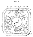
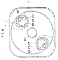
- the illustrated shield tunneling machine has a skin plate (machine body) 1 in the form of a cylinder of square cross section.
- the skin plate 1 has housed in its front end portion a cutting wheel (rotary body) 2.
- the cutting wheel 2 has a front plate 3 and a rear plate 10 and is rotatable about the central axis G (extending in the direction of propulsion of the machine) of the skin plate 1.
- the front plate 3 is formed with a plurality of radial slits 3a and has a center bit (center cutter) 4 centrally thereof.
- a multiplicity of cutter bits 5 are arranged at the edge portion of each slit 3a.
- the bits 4, and 5 provide a center cutter 6.
- a plurality of planetary cutters 7 having cutter bits 7a and 7b are arranged on front portions of the cutting wheel 2 along its periphery.
- the outer periphery of rear portion of the cutting wheel 2 is joined to the inner ring of a swivel bearing 9 secured to a bracket 8a on the skin plate 1.
- a ring 11 extending rearward is secured to the rear plate 10 of the cutting wheel 2.
- a hollow fixed ring 15 is provided in the skin plate 1 centrally thereof. The ring 11 is rotatably fitted around the fixed ring 15 with seals 16 provided therebetween.
- the planetary cutter drive gear 13 is provided at its opposite sides with brackets 8d, while the skin plate 1 is internally provided with brackets 8b.
- the brackets 8b, 8d are connected together by a pin 27d.
- a seal which prevents earth or sand from ingressing into the rear portion of the machine along with the seals 16.
- the skin plate portion serving as a seat for the seal 16a has a circular inner periphery.
- a torsion bar 23 extends through the rear plate of the cutting wheel 2 longitudinally of the machine and is attached to the plate 10.
- a lever 24 and a control lever 29 are fixed respectively to the front and rear portions of the bar 23 to provide a pivotal member which is pivotally movable about the torsion bar 23.
- a housing 25a is fitted in a hole formed in the rear plate 10.
- the torsion bar 23 is rotatably supported by a bearing 26a provided inside the housing 25a.
- the bar 23 is generally in the form of a tube and has a drive shaft 19 rotatably extending therethrough longitudinally of the machine. The rear end of the shaft 19 projects outward beyond the bar 23.
- a planetary cutter drive pinion 18a is splined as at 20a to the projecting shaft end and is in mesh with the planetary cutter drive gear 13.
- the lever 24 comprises a lever body 24a and a lever cover 24b separable therefrom.
- the lever cover 24b is formed with a shaftlike projection 24c in alignment with the drive shaft 19.
- a housing 25b accommodating a bearing 26b is secured to the rear side of the front plate 3.
- the projection 24c is rotatably supported by the bearing 26b.
- the lever 24 has rotatably supported therein the rear end of a planetary cutter rotary shaft 22, an intermedate shaft 19b and the front end of the drive shaft 19 which are arranged downward in Fig. 3.
- These shafts 19, 19b and 22 fixedly carry gears 21a, 21b and 21c, respectively.
- the gear 21a is in mesh with the gear 21b, which in turn is in mesh with the gear 21c.
- the planetary cutter 7 is splined as at 20b to the front end of the rotary shaft 22.
- the cutting wheel 2 is formed with a cutout 2b (Fig. 1) in conformity with the locus of pivotal movement of each planetary cutter 7 to preclude interference therebetween.
- the ring 11 has a plurality of brackets 8e as arranged on its outer periphery.
- a stretchable member (regulating means) 33 is pivoted to each bracket 8e by a pin 27b.
- the control lever 29 is pivoted to the movable end of the stretchable member 33 by a pin 27c.
- the member 33 is connected as contracted to the lever 29, always exerting a force on the lever in the stretching direction.
- the skin plate 1 is fixedly provided on its inner side with a guide rail (guide member) which is positioned in contact with the roller 28.
- the guide rail 34 has an inner periphery (guide face) in conformity with the desired profile (square in the present case) of excavation.
- the roller 28 is pressed against the inner periphery by the force of the stretchable member 33.
- Fig. 2 further shows a screw conveyor 66 for transporting excavated earth rearward from the interior of a chamber 2a, an erector 37 for installing segments 36 on the wall of the tunnel excavated by the machine, a shield jack 38 for propelling the machine with a reaction delivered from the segments 36, and tail seals 39 for preventing earth, sand, water and the like from flowing into the machine from around the segments 36.
- each planetary cutter 7 and the entire drive mechanism therefor revolve together about the central axis G. Since the roller 28 on the outer end of the control lever 29 is pressed against the inner periphery of the guide rail 34 by the force of the stretchable member 33, the roller revolves along a locus in conformity with the form of the inner periphery of the guide rail 34.
- the control lever 29 is connected to the torsion bar 23 and the lever 24, so that the planetary cutter 7 supported by the outer end of the lever 24 also revolves along a locus in conformity with the form of the inner periphery of the guide rail 34 about the axis G, i.e., along a locus in conformity with the desired profile of excavation.
- the planetary cutter drive gear 13 is connected to the skin plate 1 by the brackets 8b, 8d as already stated and remains in a fixed position during the rotation of the cutting wheel 2, so that each planetary cutter drive pinion 18a meshing with the gear 13 rotates about its own axis while revolving around the gear 13.
- the rotation of the pinion 18a is delivered to the planetary cutter rotary shaft 22, whereby the cutter 7 is driven at a specified speed of rotation.
- the shield tunneling machine is advanced in its entirety by the force of the jack 38, whereby the central circular region of the ground is excavated with the center bit 4 and the cutter bits 5 which are in rotation centrally of the machine.
- the region surrounding the circular region i.e. the region between the central circular region and the desired profile of excavation, can be excavated with the cutter bits 7a, 7b of the planetary cutters 7 each rotating about its own axis and revolving along a specific locus around the central region. Consequently a tunnel can be excavated which has the desired form in entire cross section.
- the earth thus excavated is led into the chamber 2a through the slits 3a formed in the front plate 3 and the cutouts 2a of the wheel 2, transported rearward continueously by the screw conveyor 66 and finally delivered onto the ground surface as by a belt conveyor 40 indicated in a broken line in Fig. 2.
- the amount of earth to be withdrawn by the screw conveyor 66 may be so adjusted that the chamber 2a is filled with the earch and maintained at an internal pressure within a predetermined range. The earth within the chamber 2a and in front thereof will then smoothly flow into the opening at the front end of the screw conveyor 66 owing to a pressure difference resulting from the operation of the conveyor 66.
- a tunnel having a desired cross sectional configuration can be continuously excavated easily by the center cutter 6 fixed to the cutting wheel 2 and the planetary cutters 7 supported by the wheel and arranged along the periphery thereof.
- the hollow fixed ring 15 is disposed in the machine body centrally thereof, with the stretchable members 33 arranged on the outer periphery of the fixed ring 15.
- the interior space of the fixed ring 15 can therefore be utilized to install the screw conveyor 66 at a suitable angle of inclination.
- the planetary cutters 7 in the first embodiment are arranged in the rear of center cutter.
- the cutting wheel 2 is divided into a front plate 3 having radial blade-like portions, and a rear plate 10.
- the front plate 3 is provided with an outer peripheral ring 3c serving as a reinforcement, and the rear plate 10 with a ring 10a having a box-shaped cross section.
- the two rings 3c and 10a are interconnected by torque arms 3b.
- the housing 25b in the first embodiment extends forward, while the portion of the lever cover 24b for supporting the planetary cutter rotary shaft 22 has a reduced amount of projection.
- the center bit 4 and the cutter bits 5 provided on the front plate 3 first excavate the ground, and the ground portion around the excavated portion is then excavated with the planetary cutters 7 as indicated by hatching in Fig. 9
- the region to be excavated by the planetary cutters 7 is much smaller with the second embodiment than with the first embodiment. This leads to the following advantages.
- a tubular housing 62 is supported by the rear plate 10 of the cutting wheel 2 and the ring 10a of box-shaped cross section.
- the housing 62 is internally provided with a pair of front and rear bearings 63.
- An agitator shaft 61 is rotatably supported by the bearings 63.
- the agitator shaft 61 has agitator blades 64 extending radially and attached to its front end inside the chamber 2a, and an agitator drive pinion 61a at its rear end.
- the pinion 61a is in mesh with the planetary cutter drive gear 13.
- the operation of the motor 35 drives the cutting wheel 2 and the planetary cutters 7, further causing the agitator shaft 61 to rotate the agitator blades 64 while revolving the shaft 61.
- This prevents high-concentration muddy water from remaining in the lower portion of the chamber 2a and also precludes the earth from lodging in the chamber 2a.
- these advantages are available by a simple arrangement of low cost without the necessity of providing an additional drive source.
- it is easy to provide plurality of agitators at required portions on a circle.
- Fig. 12 shows the agitator shaft 61 as supported at its front end by a bearing 65 provided on the front plate 3 of the cutting wheel 2.
- the shaft 61 can then be supported at the opposite sides of the agitator blades 64, becomes more resistant to bending and is therefore advantageous from the viewpoint of strength.
- the shape, size and number of agitator blades may be determined suitably in accordance with the type of earth to be handled. For example, the same effect as above can be achieved by providing an increased number of rods to serve as blades.
- the agitator blades may be arranged as desired insofar as they do not interfere with other members.
- the drive conversion mechanism of the present invention is not limited to the one shown in Figs. 3 and 8.
- the front end of the drive shaft 19 may extend through the lever cover 24b for a bearing 26b to support the end of the extension as seen in Fig. 13.
- the train of gears 21a to 21c may be replaced by sprockets 30a fixed to the shafts 22, 19 and chains 31 reeved around the respective pairs of sprockets, whereby the same result as already described can be achieved.
- the configuration of the guide member for use in the invention is not limited to a square form like the guide member 34 but can be circular, egg-shaped, horseshoe-shaped or otherwise, as determined suitably in conformity with the desired profile of excavation.
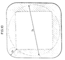
- Fig. 15 shows the outer periphery 1a of the skin plate 1, a small circle 100 (broken line) representing the cross sectional shape to which the ground is excavated by the rotation of the cutting wheel 2, and a large circle 101 (broken line) representing the cross sectional shape to which the ground is excavated by the rotation of the cutting wheel, with the center of each planetary cutter 7 positioned the largest distance away from the center of the small circle 100.
- the locus of revolution of the planetary cutter can be determined as desired within the range surrounded by the small circle 100 and the large circle 101.
- tunnels can be excavated satisfactorily using a skin plate having a cross sectional shape in conformity with that of the tunnel.
- Fig. 15 shows the outer periphery 1a of the skin plate 1 which is in the form of a cylinder with a square cross section as an example, the diagram shows that the outer periphery of the skin plate 1 is within the above-mentioned range.
- Figs. 16 and 17 respectively show a horseshoe-shaped periphery and a periphery in the form of an elongated circle which are within the above range.
- the skin plate 1 to be used has a horseshoe-shaped periphery or elongated circular periphery, and the guide rail to be used is so shaped as to enable the planetary cutter to revolve along a locus conforming to the peripheral shape.
- the single shield tunneling machine is adapted to readily give various profiles of excavation merely by suitably changing the shape of the guide rail and the skin plate.
- the guide member which is in the form of the guide rail 34 in the foregoing embodiments, may alternatively be in the form of an internal gear as an example, for use with a pinion meshable therewith instead of using the roller 28.
- the stretchable member 33 is used in the foregoing embodiments as means for pressing the roller 28 against the guide rail 34, the guide rail 34 may have a double structure composed of inner and outer segments for passing the roller 28 therebetween. The stretchable member 33 can then be dispensed with.
- a bearing for example, may be fixedly provided around the fixed ring 15 shown in Fig. 2 for the bearing to support the cutting wheel 2.
- a fourth embodiment will be described with reference to Fig. 4.
- the cutting wheel 2 and the planetary cutters 7 are driven by the motor 35 having a reduction gear and serving as a common drive source in the case of the shield tunneling machine of the first embodiment
- this embodiment is so adapted that the planetary cutters 7 are driven by a motor 45 (planetary cutter drive means) with a reduction gear independently of the cutting wheel 2.
- a planetary cutter drive gear 13 having an increased width is rotatably provided around the ring 11 with a bearing 14 interposed therebetween.
- the same pinion 18a as used in the first embodiment is in mesh with the front half portion of the gear 13.
- a drive pinion 18d on the drive shaft of the motor 45 is in mesh with the rear half portion of the gear 13.
- the motor 45 is positioned away from the motor 35 circumferentially of the ring 11 and is secured by a mount 45a to the brackets 8c.
- the motor 35 when driven, rotates the cutting wheel drive gear 12, the ring 11 and the cutting wheel 2 together. Concurrently with this, the motor 45 is driven, whereby the torque is transmitted to the planetary cutter drive pinion 18a through the gear 13 and further to the rotary shaft 22 of each planetary cutter 7 through the mechanism shown in Fig. 3. Consequently, each planetary cutter 7 is driven at a speed independently of the wheel 2.
- each of the planetary cutter 7 and the cutting wheel 2 is settable to a speed of rotation independently of the other by setting the motors 35, 45 to suitable speeds of rotation individually. Accordingly, the cutter 7 is rotatable at a desired speed, for example, according to the type of the earth to be worked on, independently of the speed of the cutting wheel 2.
- the planetary cutter drive gear 13 may have a double structure comprising a front (first) gear 13a and a rear (second) gear 13b as seen in Fig. 19.
- the front gear 13a is in mesh with the planetary cutter drive pinion 18a, and the rear gear 13b with the drive pinion 18d.
- the reduction ratio for the planetary cutter 7 is then suitably settable by varying the gear ratio between the two gears 13a, 13b.
- the planetary cutter 7 can be driven either forward or reversely, so that the drive mechanism C, the lever 24, etc. can be designed easily free of the restriction to be imposed by the direction of rotation of the cutter 7. Furthermore, it is possible to remove the stones or the like biting in between the periphery of the cutter 7 and the skin plate 1, or to correct rolling during excavation, by changing the direction of rotation of the cutter 7.
- the roller 28 on the outer end of the lever 29 is pressed against the guide rail 34 by the stretchable member 33 to thereby cause the planetary cutter 7 to revolve along the desired locus, whereas with this embodiment, the guide rail 34 is dispensed with as seen in Fig. 20.
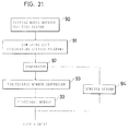
- the cutter 7 is adapted to revolve along the desired path by controlling the operation of the stretchable member 33 by the drive control system shown in Fig. 21.
- a cutting wheel (rotary body) rotated position sensor 90 detects the rotational displacement (e.g. angle) of the cutting wheel 2 from a suitable reference position thereof (e.g. the position shown in Fig. 1).
- a stretch sensor 94 for the stretchable member 33 detects the amount of actual stretch or contraction of the stretchable member 33 relative to a reference length of the member 33 suitably determined.
- the sensor 94 comprises a potentiometer or the like.
- the reference length to be determined is, for example, the length of the stretchable member 33 when the control lever 29 is in the position shown in Fig. 1.
- a computing unit 91 has stored therein a program for calculating the amount of stretch or contraction of the stretchable member 33 required relative to the rotational displacement of the cutting wheel in order to excavate a predetermined cross section.
- the unit 91 instantaneously calculates the amount of stretch or contraction required of the member 33 relative to the rotational displacement of the wheel 2 received from the rotated position sensor 90 as will be described later below.
- a comparator 92 compares the displacement received from the stretch sensor 94 with the required displacement received from the computing unit 91, feeds a stretching or contracting command to a stretchable member controller 93 to eliminate the difference therebetween, and gives a stop command upon the elimination of the difference.
- the stretchable member controller 93 controls the actual stretch or contraction of the member 33.
- the controller 93 comprises a servo vale for controlling the supply of oil to the cylinder, and a control device for the servo valve.
- the controller 93 and the comparator 92 constitute comparative control means.
- the cutting wheel 2 is drivingly rotated, while the drive control system controls the operation of each stretchable member 33 so that the planetary cutter 7 revolves along the desired locus.
- the computing unit 91 calculates the amount of stretch or contraction of the stretchable member 33 required to obtain the desired cross section relative to the rotated position of the cutting wheel 2. Based on the result of comparison of the actual stretch or contraction amount with the calculated amount, the operation of the stretchable member 33, i.e. the drive of the pivotal member comprising the control lever 29, etc. is controlled.
- the stretchable member 33 is then stretched to increase the distance from the axis G to the cutter 7 (i.e., radius of revolution) to thereby increase the region to be excavated by the cutter 7 to the corner portion. If the planetary cutter 7 is positioned as opposed to the midpoint of the side of the square skin plate 1, the member 33 is contracted to decrease the distance from the axis G to the cutter 7. The control thus effected enables the planetary cutter 7 to revolve along a locus in conformity with the desired profile of excavation (generally square to rectangular in this case).
- each pivotal member is controlled by the drive control system to thereby revolve the planetary cutter 7 along the desired locus, so that the ground can be excavated with various cross sectional shape merely by changing the program stored in the computing unit 91.
- the ground can be overcut with use of the control system advantageously as will be described below with reference to Fig. 22.
- the drawing shows hatched regions J, K, L and M around the outer periphery 1a of the skin plate 1 which are to be overcut.
- the planetary cutters 7 are so controlled as to move along the outer periphery of the skin plate 1 according to the program stored in the computing unit 91.
- the computing unit 91 has stored therein a program for moving each planetary cutter 7 along a profile 96a including the region J around the skin plate periphery, and respective programs for moving the cutter 7 along a profile 96b including the region K, along a profile 96c including the region L and along a profile 96d including the region M.
- the computing unit 91 is provided with a circuit for selecting one of the five programs as desired to specify one of the five profiles of excavation as required.
- the control system thus constructed achieve the following advantage of overcutting.
- the ground portion above the upper side of the skin plate 1 is also excavated for overcutting.
- the excavation operation is continued in this state, a space with a cross section corresponding to the region J above the skin plate 1 is formed, and the frictional resistance between the plate 1 and the earth decreases in this portion.
- the bottom of the skin plate 1 remains in contact with the ground. Accordingly, the difference in frictional resistance between the portion above the skin plate 1 and the portion below the plate 1 gradually increases, consequently permitting the machine to escape toward the upper side where the resistance is lower. Thus, the machine is propelled gradually upward.
- the direction of advance of the machine is easily variable upward, downward, leftward or rightward by suitably selecting one of the excavation programs for the profiles 96a to 96d shown in Fig. 22, the machine thus adapted to excavate the ground along steep curves. Further if the computing unit has stored therein programs for overcutting the respective four corners, the posture of the machine can be easily corrected against rolling.
- each planetary cutter 7 is driven by the motor 45 independently of the cutting wheel 2.
- the stretchable member 33 may be operated under the control of the drive control system to obtain the same advantage as above.
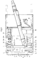
- the shield tunneling machine shown in Figs. 23 to 25 consists essentially of a skin plate 1 having a square to rectangular cross section, a center cutter 102 so supported as to be rotatable about the horizontal central axis X of the skin plate 1 (center cutter axis extending in the direction of propulsion of the machine), a large rotary table (rotary body) 102 rotatable about the center cutter axis X, a pair of side cutters (planetary cutters) 104 arranged around the center cutter 102 and each rotatable about an axis parallel to the cutter axis X, and a guide frame 105 for guiding the movement of the rotary shaft 141 of the side cutter 104.
- the center cutter 102 is connected to the front end of a screw conveyor 121.
- An electric motor 122 for the center cutter 102 is attached to the rear end of the conveyor 121.
- the center cutter 102 and the screw conveyor 121 are rotatable about the axis X at the same time by the operation of the motor 122.
- the screw conveyor 121 is covered with a fixed tube 123 secured to the skin plate 1 and a movable tube 124 having the motor 122 attached thereto and has its rear end rotatably supported by the movable tube 124.
- the movable tube 124 and the fixed tube 123 are splined to each other as at 1231, 1241 and are movable along the cutter axis X relative to each other.
- the screw conveyor 121 is splined to the fixed tube 123 as at 1211, 1232 at their front ends and is movable relative to the tube 123 along the axis X.
- the movable tube 124, the screw conveyor 121 and the center cutter 102 are movable forward and rearward between a usual position (indicated in solid line in Fig. 23) and a projected position (indicated in two-dot-and-dash line in Fig. 23) by the extension or contraction of a cylinder 125 connected between the movable tube 124 and the skin plate 1.
- the fixed tube 123 is provided on the upper side of its front end with a hopper 1233 which is opened to the interior space 131 of the large table 103, while the movable 124 is formed in the bottom side of its rear end with a discharge opening 1242 positioned above a belt conveyor 106.
- the muck led into the large table 103 is discharged onto the belt conveyor 106 by the operation of the screw conveyor 121.
- the large rotary table 103 is supported by the outer periphery of the fixed tube 123 and the inner periphery of the skin plate 1 rotatably about the center cutter axis X.
- the large table 103 is provided with a pair of small rotary tables 107 arranged symmetrically with respect to the axis X.
- Each of the small tables 107 is supported by the large table 103 rotatably about an axis parallel to the center cutter axis X.
- a side cutter rotary shaft 141 is supported by the small table 107 eccentrically therewith and is rotatable about an axis parallel to the axis X.
- the rotary shaft 141 fixedly carries the side cutter 104 at its front end and has a guide gear 142 and a roller 143 attached to its rear end.
- Fixed to the inner periphery of the skin plate 1 is the guide frame (regulating member) 105 which is square to rectangular and similar in shape to the outer periphery of the skin plate 1.
- the guide frame 105 is formed with a guide portion 151 along its inner periphery and has a gear 152 comprising a multiplicity of pins arranged on the inner periphery.
- the side cutter rotary shaft 141 is so disposed that the guide gear 142 is in mesh with the pin gear 152, with the roller 143 in contact with the guide portion 151.
- the side cutter 104 and the guide frame 105 are so sized that when the guide gear 142 is in mesh with the pin gear 152, the outer periphery of the side cutter 104 is positioned at the front-side outer periphery 1a of the skin plate 1.
- the side cutter 104 is further so sized that the locus circle of rotation of the center cutter 102 partly laps over the locus circle of rotation of the side cutter 104.
- the fixed tube 123 is provided on its outer periphery with a pair of support arms (pivotal member) 108 rotatably about the tube 123.
- the side cutter rotary shaft 141 is rotatably connected to the outer end of each support arm 108.
- the support arm 108 comprises a pair of arm portions 181, 182 pivoted to each other, and an air cylinder 183 connected between the arm portions 181, 182.
- the side cutter rotary shaft 141 is pressed against the pin gear 152 on the guide frame 105 by the stretching force of the air cylinder 183, whereby the guide gear 142 is forced into meshing engagement with the pin gear 152 regardless of the position of the rotary shaft 141 relative to the guide frame 105.
- a transmission shaft 133 rotatably supported by the skin plate 1 has at its one end a gear 1331 meshing with the pin gear 132 and at the other end thereof a gear 1332 meshing with an output gear 1341 on a side cutter electric motor 134.
- the large table 103 is rotatable about the center cutter axis X by the torque of the motor 134 transmitted through the shaft 133.
- the large table 103 is formed in its front plate with a plurality of muck inlets 135 as arranged radially.
- a plurality of scraper plates 136 are radially arranged in the interior space 131 of the large rotary table 103 for placing the muck into the hopper 1233.
- Fig. 23 further shows a shield jack 191, a slide jack 192, segments 193 and a segment assembling erector 194.
- the side cutter motor 134 when driven, transmits a torque to the large rotary table 103 through the transmission shaft 133 and the pin gear 132, rotating the large table 103 about the cutter axis X clockwise in Fig. 25. With this rotation, the small rotary tables 107 and the side cutter rotary shafts 141 revolve about the axis X.
- the guide gear 142 on each side cutter rotary shaft 141 is in mesh with the pin gear 152 of the guide frame 105, with the roller 143 in contact with the guide portion 151, so that the revolution of the small table 107 about the center cutter axis X revolves the side cutter shaft 141 and the side cutter 104 with the table 107.
- the shaft 141 is mounted on the small table 107 eccentrically therewith, the rotation of the large table 103 also rotates the small table 107 about the shaft 141 counterclockwise in Fig. 25, whereby the variation in the distance from the axis X to the guide frame 5 is absorbed.
- the guide gear 142 is pressed against the pin gear 152 on the guide frame 105 by the air cylinder 183 on the support arm 108 and therefore properly rotates and moves along the inner periphery of the guide frame 105, with the result that the locus of revolution of the side cutter shaft 141 conforms to the shape of the inner periphery of the guide frame 105.
- the operation of the center cutter motor 122 rotates the center cutter 102 in a direction opposite to the direction of rotation of the side cutter 104 to excavate the cutting face in front of the machine into a circular portion CA (see Fig. 27) centrally thereof.
- the ground is excavated at the region between the circular portion CA and the square contour S of cross section of the tunnel defined by the outer periphery 1a of the front side of the machine, by each side cutter 104 which revolves along a substantially square locus T along the guide grame 105 while rotating about its own axis.
- the cutting face in front of the machine can be excavated with a cross section (e.g. square cross section in the present case) other than a circular one continuously, whereby a tunnel having this cross section can be formed.
- a cross section e.g. square cross section in the present case
- the ground can be excavated with the cross sectional configuration required of the tunnel without necessitating excessive excavation. This results in a corresponding cost reduction.
- each side cutter 104 is made different from the large table 103, and the side cutter 104 is made different from the center cutter 102, whereby the muck to be taken in through the inlets 135 can be ground between the rear face of the cennter cutter 102 and the front face of the side cutter 104 and between the rear face of the side cutter and blades 1351 on the front side of front wall of the table 103 at the inlets 135. Accordingly, the machine has the advantage that it need not be equipped with a crusher.
- the center cutter 102 differs from each side cutter 104 in the direction of rotation, so that the rotational reaction forces thereof are offset by each other, whereby the machine can be prevented from rotation.
- the cylinder 125 is contracted to thereby advance the center cutter 102 to the projected position (indicated in the two-dot-and-dash line in Fig. 23) and cause the cutter to bite into the ground face to be excavated.
- the rotation is then corrected by driving the side cutters 104 and thereby rotating the machine in a direction opposite to that of the rotation, with the center cutter 102 serving as a fixed point.
- the rotation can be corrected or remedied automatically by detecting the pressure exerted by the cutting face on the center cutter with an unillustrated pressure sensor and detecting the angle of rotation of the skin plate 1 with a position sensor.
- the skin plate 1 When the tunnel has been excavated by the machine of the above embodiment, the skin plate 1 may be left at the excavation site, while the main internal components such as the large rotary table 103, center cutter 102 and side cutters 104 may be withdrawn through the tunnel and recovered to above the ground for reuse. This achieves a remarkable reduction in the tunnel excavation cost unlike the case wherein the tunneling machine is left discarded as buried in the site of excavation every time a tunnel has been completed.
- slide means is provided for the machine for rearwardly moving the large table 103 along with the support wall 112 of the skin plate 1 for supporting the table 103 and the screw conveyor fixed tube 123.
- Each side cutter 104 is positioned at the corner of the square as seen in Fig. 25, and the small table 107 only is rotated with the air cylinder 183 of the support arm 108 relieved of pressure to thereby move the side cutter 104 inward from the outer peripheral edge of the large table 103.
- the large table 103 is then withdrawn along with the center cutter 102, the side cutters 104, etc. by the slide means.
- the pair of side cutters 104 are arranged symmetrically with respect to the center cutter axis X according to the above embodiment, a single side cutter or at least three side cutters may alternatively be provided. However, it is desirable to provide at least two side cutters in a radial and uniform arrangement from the viewpoint of preventing the rotation of the machine.
- FIGS. 1-10 show a center cutter shaft 120a which has rotatably mounted thereon two pin gears 121a integral with each other.
- a pair of front and rear support plates 122a are rotatably mounted on the shaft 120a.
- a pair of transmission shafts 130a coupled to one of the pin gears 121a are supported by the support plates 122a in parallel to the axis X of the center cutter shaft 120a.
- a pair of connecting members 131a are rotatably connected each at its one end to the transmission shaft 130a.
- a side cutter rotary shaft 141a is rotatably supported by the other ends of the connecting members 131a.
- the transmission shaft 130a has attached thereto a gear 130b at one end thereof and a pair of pin gears 130c at intermediate portions thereof.
- the side cutter shaft 141a has a pair of transmission gears 141b mounted thereon.
- the transmission shaft 130a and the side cutter shaft 141a are interconnected by the connecting members 131a so that the pin gears 130c are in mesh with the respective transmission gears 141b.
- the side cutter shaft 141a further has mounted thereon a guide gear 142a positioned between the pair of transmission gears 141b.
- the skin plate 1 has attached thereto a guide frame 105a provided with a pin gear 152a on its inner periphery which is square or rectangular.
- the guide gear 142a is so sized as to mesh with the pin gear 152a.
- a side cutter electric motor 134a has an output gear 134a in mesh with the other pin gear 121a on the center cutter shaft 120a.
- the motor 134a when driven, delivers a torque through the pin gears 121a to the transmission shaft 130a, which in turn transmits the torque to the side cutter shaft 141a via the pair of pin gears 130c and the pair of transmission gears 141b, whereby the side cutter is drivingly rotated.
- the guide gear 142a rotates along the pin gear 152a on the guide frame 105a, and the roller 141c moves along by being guided by contact with the guide portion 151a, with the result that the side cutter shaft 141a revolves about the center cutter axis X along the guide frame 105a, following a square locus similar to the guide frame 105a. Consequently a tunnel can be excavated with a square cross section.
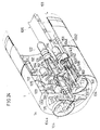
- the shield tunneling machine shown in Figs. 30 to 37 has a skin plate 1 in the form of a cylinder with a rectangular or square cross section.
- the skin plate 1 houses a cutting wheel 2 in its front end portion.
- the wheel 2 is attached to the front end (left end in Fig. 31) of a center shaft 31 extending in the direction of propulsion of the machine and its rotatable therewith.
- the outer periphery of the cutting wheel 2 and the rear end of the center shaft 203 are supported on the skin plate 1 by bearings 204 and 205, respectively.
- the bearing 205 supports radial and thrust loads.
- the thrust load acting on the cutting wheel 2 during excavation is transmitted to the skin plate 1 through the shaft 203, the bearing 205 and a bearing support frame 206 extending from the skin plate 1.
- the wheel 2 is supported by the bearings 204 and 205 with respect to both the radial direction and thrust direction and is free to rotate about the axis of the centre shaft 203.
- a large gear 207 is fixed to the rear end (right end in Fig. 31) of the center shaft 203.
- the bearing support frame 206 is provided with a gear casing 208 having a lid 209, to which two wheel drive geared motor (rotary body drive means) 210 are attached.
- a pinion 211 mounted on the output shaft of each motor 210 is in mesh with the large gear 207. Accordingly, the geared motors 210, when operated, drivingly rotate the cutting wheel 2.
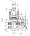
- the cutting wheel 2 has an interior space, i.e., a chamber 212, and a pair of bosses 213 arranged in the chamber 212 symmetrically with respect to the center shaft 203 and having a cylindrical hole.
- a rotary wheel (small rotary body) 215 having an eccentric bore 214 is rotatably inserted in each of these bosses 213 with bearings 216 provided therebetween.
- a planetary cutter drive shaft 217 is rotatably inserted in the eccentric bore 214, with bearings 218 fitted around the shaft.
- the shaft 217 has a gear 219 at its rear end and is fixedly provided at its front end with a planetary cutter 222 having cutter bits 231 along the entire outer periphery of its front side.
- a cover 220 is attached to the rear end of the rotary wheel 215 and has mounted thereon a planetary cutter drive geared motor (planetary cutter drive means) 221.
- a pinion 2111 mounted on the output shaft of the motor 221 is in mesh with the gear 219. Accordingly, the motor 221, when operated, drivingly rotates a planetary cutter 222.
- the rear end of the rotary wheel 215 is toothed over the entire circumference thereof to provide a gear 223.
- Two rotary wheel drive assemblies 226 are mounted on the center shaft 203 by a bracket 227.
- Each of these assemblies 226 comprises a rotary wheel drive geared motor 224, a pinion 2112 mounted on the output shaft of the motor 224, an idle gear 225 meshing with the pinion 2112, etc.
- the idle gear 225 is in mesh with the gear 223 at the rear end of the rotary wheel 215. Accordingly, the motor 224, when operated, drivingly rotates the rotary wheel 215 via the pinion 2112 and idle gear 225.
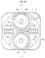
- the cutting wheel 2 is provided on its front side with a face plate 230 which is locally cut out only at the portions where the planetary cutters 22e are disposed.
- the front faces of the planetary cutters 222 are approximately flush with the front face of the cutting wheel 2 (i.e., the front face of the face plate 230). With the face plate 230 thus provided, the planetary cutters 222 only will not greatly project forward. This serves to stabilize the cutting face (the face of ground to be excavated by the tunneling machine), assuring the machine of a smooth excavating operation.
- a multiplicity of cutter bits 2311 and 2312 are arranged locally on the face plate 230 for cutting the earth like the planetary cutters 222.
- the face plate 230 and the cutter pits 2311, 2312 on the surface thereof constitute a center cutter rotatable about the center shaft 203.
- the face plate 230 and the cutting wheel 2 are formed with a plurality of windows 232 in communication with the chamber 212 of the wheel 2.
- the earth removed by the cutter bits 231, 2311, 2312 is led into the chamber 212 through the windows 232, transported rearward by a screw conveyor (not shown) disposed inside the center shaft 203 and then discharges from the machine as by a belt conveyor (not shown).
- the center shaft 203 is provided therearound with a slip ring 233 for transmitting power (electricity or hydraulic pressure) to the rotary wheel drive geared motors 224 and the planetary cutter drive geared motors 221.
- the skin plate 1 has in its rear portion a shield jack (propelling means) 234 and an erector 235 for placing segments 250 along the wall of the excavated tunnel.
- the shield tunneling machine is internally provided with a drive control system as shown in the block diagram of Fig. 38.
- the illustrated system includes a cutting wheel (rotary body) rotated position sensor 280 for detecting the rotational displacement (e.g. angle) of the cutting wheel 2 relative to the reference position of the cutting wheel 2.
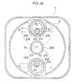
- the reference position is, for example, the position in which the center P2 of one of the two rotary wheels 215 is located immediately above the center P1 of the cutting wheel 2 (see Fig. 34).
- a rotary wheel rotated position sensor 284 detects the rotational displacement of the rotary wheel 215 relative to the reference position of the wheel 215.
- the reference position is, for example, the position where the center P3 of the planetary cutter 222 is located in the closest proximity to the center P1 of the wheel 2.
- a computing unit 281 has stored therein a program for calculating the rotational displacement of the rotary wheel 215 required relative to the rotational displacement of the cutting wheel 2 and instantaneously calculates the required rotational displacement of the wheel 215 relative to that of the wheel 2 received from the rotated position sensor 280 as will be described in detail later.
- a comparator 282 compairs the rotational displacement received from the rotary wheel rotated position sensor 284 with the displacement received from the computing unit 281, feeds to a controller 283 for the rotary wheel drive geared motor 224 a forward or reverse rotation command so as to rotate the wheel 215 in a direction to eliminate the difference between the tow displacements, and gives a stop command upon the elimination of the difference.
- the comparator 282 and the controller 283 constitute comparative control means.
- a servo value is used as the controller.
- the geared motors 221 are operated to drive the respective planetary cutters 222, and the geared motors 210 are then driven to rotate the cutting wheel 2.
- the shield jack 234 is gradually extended, the jack 234 comes into contact with the segment 250 already installed in place, whereupon the jack advances the tunneling machine in its entirety with a propelling reaction force delivered from the segment 250.
- the cutting wheel 2 is in rotation, cutting the earth with the cutter bits 2311 and 2312 provided on the face plate 230 and in circular motion, and each planetary cutter 222 also cuts the earth with its cutter bits 231 while rotating about its own axis and revolving.
- the center or axis P3 of the planetary cutter drive shaft 217 through the center of the planetary cutter 222 is a distance l1 away from the center P2 of the rotary wheel 215. Accordingly, the rotation of the rotary wheel 215 moves the center P3 of the drive shaft 217 toward and away from the center P1 of the cutting wheel 2, consequently moving the cutter 222 toward and away from the wheel center P1.
- the distance l from the center P1 of the cutting wheel 2 to then center P3 of the planetary cutter 222 can be varied over the range expressed by: l2 + l1 ⁇ l ⁇ l2 - l1 where l2 is the distance from the center P1 of the cutting wheel 2 to the center P2 of the rotary wheel 215.
- the rotary wheel 215 is to be rotated to a position where the planetary cutter 222 passes the corner position of the square section, with the distance l increasing to a maximum.
- each rotary body 215 as positioned in Fig. 34 is rotated through 180°, whereby the region of excavation can be enlarged to the corner portions of the square.
- the rotary wheels 215 are so rotated that the distance between the planetary cutters 222, and accordingly the distance l, will decrease.
- the ground can be excavated with a specified distance automatically by varying the rotated position of the rotary wheels 215 in accordance with the angle of rotation of the cutting wheel 2.
- the rotational displacement of the rotary wheel 215 required to obtain the desired cross section relative to the rotated position of the wheel 2 is calculated and then compared with the actual rotational displacement detected, by the computing unit 281, and the rotation of the rotary wheel 215 is controlled based on the result of comparison, whereby the planetary cutter 222 can be revolved about the center P1 along a locus in conformity with the desired cross section to be excavated.
- the rotary wheel 215 is rotated forward and reversely over the range of 180°.
- the present shield tunneling machine for practicing the method of the invention automatically readily excavates the ground in various cross sectional configurations such as those shown in Figs. 15 to 17 when the program stored in the computing unit 281 is suitably changed. Furthermore, the machine is adapted to overcut the ground advantageously in the manner already described.
- a ninth embodiment will be described with reference to Figs. 39 and 40.
- the rotary wheel drive assemblies 226 in the above embodiment are replaced by hydraulic cylinders 240 for drivingly rotating the rotary wheels 215.
- an intermediate plate 2d of the cutting wheel 2 is provided with a pair of cylinder support posts 241. Brackets 2421 and 2422 are attached to each post 241 and an outer peripheral portion of each rotary wheel 215, respectively.
- the hydraulic cylinder 240 is pivoted at its opposite ends to the brackets 2421, 2422.
- the present embodiment has the advantage of being very simple in construction although the range of rotation of the rotary wheel 215 is small.
- the drive control system of this embodiment includes a hydraulic cylinder controller (servo valve) in place of the motor controller 283 shown in Fig. 38.
- the number and arrangement of planetary cutters are not limited specifically but can be determined suitably in accordance with conditions such as the type of earth to be handled.
- the speed of rotation of members such as cutting wheel 2 and the pivotal member may be predetermined for a particular cross section of excavation, and an angular correction may be made periodically in the course of excavation for a controlled operation.
Landscapes
- Engineering & Computer Science (AREA)
- Mining & Mineral Resources (AREA)
- Environmental & Geological Engineering (AREA)
- Life Sciences & Earth Sciences (AREA)
- General Life Sciences & Earth Sciences (AREA)
- Geochemistry & Mineralogy (AREA)
- Geology (AREA)
- Excavating Of Shafts Or Tunnels (AREA)
Claims (30)
- Maschine zum Schildvortrieb mit einem wählbaren Querschnitt, mit einem Maschinenkörper (1), einem am Maschinenkörper angeordneten Mittenschneider (6) derart, daß er um eine sich in die Richtung des Vortriebs des Körpers erstreckende Achse (G) drehbar ist und einem derart angeordneten Rotationskörper (2), daß er um die gleiche Achse wie der Mittenschneider drehbar ist, gekennzeichnet durch einen Planetenschneider (7), der am Rotationskörper angeordnet ist derart, daß er radial vom Rotationskörper bewegbar ist und einer Betätigungseinrichtung (24) zum Bewegen des Planetenschneiders radial des Rotationskörpers, damit sich der Planetenschneider während der Rotation des Rotationskörpers entlang einer Ortskurve dreht, so daß der Planetenschneider den Bereich zwischen dem Profil der Abtragung durch den Mittenschneider und dem gewünschten Abtragungsprofil abträgt.
- Maschine nach Anspruch 1, dadurch gekennzeichnet, daß der Planetenschneider (7) hinter dem Mittenschneider angeordnet ist.
- Maschine nach Anspruch 1, dadurch gekennzeichnet, daß der Rotationskörper (2) am Innenumfang des Maschinenkörpers angeordnet ist.
- Maschine nach Anspruch 1, dadurch gekennzeichnet, daß der Rotationskörper am Außenumfang eines Hohlrings (15) angeordnet ist.
- Maschine nach Anspruch 1, dadurch gekennzeichnet, daß die Ortskurve der Umlaufbewegung des Planetenschneiders quadratisch bis rechteckig ist.
- Maschine nach Anspruch 1, dadurch gekennzeichnet, daß die Ortskurve der Umlaufbewegung des Planetenschneiders hufeisenförmig ist.
- Maschine nach Anspruch 1, dadurch gekennzeichnet, daß die Ortskurve der Umlaufbewegung des Planetenschneiders in der Form eines, eines langgestreckten Kreises und einer Ellipse ist.
- Maschine nach Anspruch 1, dadurch gekennzeichnet, daß die Ortskurve der Umlaufbewegung des Planetenschneiders eiförmig ist.
- Maschine nach Anspruch 1, dadurch gekennzeichnet, daß der Maschinenkörper ein Hautblech mit einer querschnittlichen Form in Übereinstimmung mit dem gewünschten Abtragungsprofil ist.
- Maschine nach Anspruch 1, dadurch gekennzeichnet, daß der Mittenschneider (6) am Rotationskörper (2) festgelegt ist.
- Maschine nach Anspruch 1, dadurch gekennzeichnet, daß der Mittenschneider (6) antreibbar drehbar ist in einer Richtung entgegengesetzt zur Richtung der Rotation des Rotationskörpers.
- Maschine nach Anspruch 1, dadurch gekennzeichnet, daß die Betätigungseinrichtung ein bewegbar am Rotationskörper an einer Stelle von dessen Drehachse weg angeordnetes Schwenkglied (24) aufweist, welches den Planetenschneider (7) daran an einer Stelle von der Achse dessen Schwenkbewegung weg trägt, ein Führungsglied (34) mit einer Führungsform in Übereinstimmung mit dem gewünschten Abtragungsprofil besitzt und eine Einstelleinrichtung (33) zum Drücken des bewegbaren Endes des Schwenkglieds gegen das Führungsglied zum Einstellen der Ortskurve der Umlaufbewegung des Planetenschneiders aufweist.
- Maschine nach Anspruch 1, dadurch gekennzeichnet, daß das Schwenkglied einen Torsionsstab (23), einen am vorderen Abschnitt des Torsionstabs befestigten Hebel (24) aufweist, an dessen bewegbarem Ende der Planetenschneider drehbar angeordnet ist und einen am hinteren Abschnitt des Torsionsstabs befestigten Steuerhebel (29) besitzt, der ein gegen das Führungsglied gedrücktes bewegbares Ende aufweist.
- Maschine nach Anspruch 12, dadurch gekennzeichnet, daß die Einstelleinrichtung ein als Zusammengezogenes mit dem Schwenkglied verbundenes streckbares Glied (33) aufweist, das immer in der Streckrichtung eine Kraft auf das bewegbare Ende des Schwenkglieds ausübt.
- Maschine nach Anspruch 12, dadurch gekennzeichnet, daß das Führungsglied eine Führungsschiene (34) mit einem in Übereinstimmung mit dem gewünschten Abtragungsprofil geformten Innenumfang ist und daß eine Rolle (28) in Kontakt mit dem Innenumfang der Führungsschiene am bewegbaren Ende des Schwenkglieds angeordnet ist.
- Maschine nach Anspruch 12, dadurch gekennzeichnet, daß das Führungsglied (34) ein gezahntes innenverzahntes Rad in Übereinstimmung mit dem gewünschten Abtragungsprofil ist und daß ein mit dem innenverzahnten Rad kämmendes Ritzel (28) am bewegbaren Ende des Schwenkglieds angeordnet ist.
- Maschine nach Anspruch 1, dadurch gekennzeichnet, daß die Betätigungseinrichtung ein schwenkbar bewegbar am Rotationskörper (2) an einer Stelle von dessen Drehachse weg angeordnetes Schwenkglied (24) aufweist, das den Planetenschneider (7) daran an einer Stelle von der Achse dessen Schwenkbewegung weg trägt, eine Einrichtung (33) zum Antreiben des Schwenkglieds besitzt und eine Antriebssteuerung zur Steuerung des Antriebs des Schwenkglieds aufweist, so daß sich der Planetenschneider entlang einer Ortskurve dreht, um den Bereich zwischen dem Abtragungsprofil durch den Mittenschneider und dem gewünschten Abtragungsprofil abzutragen.
- Maschine nach Anspruch 17, dadurch gekennzeichnet, daß das Schwenkglied einen Torsionsstab (19) aufweist, einen am vorderen Abschnitt des Torsionsstabs befestigten Hebel (7) besitzt, der an seinem bewegbaren Ende drehbar den Planetenschneider trägt und einen am hinteren Abschnitt des Torsionsstabs befestigten Steuerhebel (29) besitzt, mit dessen bewegbarem Ende die Schwenkgliedantriebseinrichtung (33) verbunden ist.
- Maschine nach Anspruch 17, dadurch gekennzeichnet, daß die Antriebssteuerung einen Sensor (90) zum Erfassen der absolut gedrehten Position des Rotationskörpers, einen Sensor (94) zum Erfassen der bewegten Position des Schwenkglieds relativ zum Rotationskörper, eine Recheneinheit (91) zur Berechnung des Betrags der vom Schwenkglied relativ zum Drehversatz des Rotationskörpers geforderten Drehbewegung und eine Vergleichssteuereinrichtung (92) aufweist zum Vergleichen der vom Drehgliedbewegungspositionssensor empfangenen Versetzung mit der von der Recheneinheit empfangenen berechneten Versetzung und zum Steuern des Antriebs des Schwenkglieds, um den Unterschied zwischen den Versetzungen zu beheben.
- Maschine nach Anspruch 19, dadurch gekennzeichnet, daß die Recheneinheit (91) ausgebildet ist zur Berechnung des Betrags der vom Schwenkglied geforderten Schwenkbewegung selektiv für einen Grundabtragungsquerschnitt und eine Vielzahl von Querschnitten, die jeweils den Grundabtragungsquerschnitt plus einen zusätzlichen Querschnitt an jeder der oberen, unteren, linken und rechten Seiten des Grundquerschnitts aufweist.
- Maschine nach Anspruch 1, gekennzeichnet durch ein am Rotationskörper (2) drehbar angeordnetes kleines Rotationsglied (215), wobei der Planetenschneider drehbar am kleinen Rotationsglied an einer Stelle von dessen Drehachse weg befestigt ist.
- Maschine nach Anspruch 1, gekennzeichnet durch eine Antriebseinrichtung zum Antreiben des Rotationskörpers und eine Antriebsumkehrvorrichtung zum Umkehren der Rotation des Rotationskörpers zur Rotation des Planetenschneiders, wobei sowohl der Mittenschneider als auch der Planetenschneider durch die Antriebseinrichtung drehbar antreibbar sind.
- Maschine nach Anspruch 22, dadurch gekennzeichnet, daß die Antriebsumkehrvorrichtung ein am Maschinenkörper festgelegtes Planetenschneiderantriebszahnrad (13) und ein mit der Drehwelle des Planetenschneiders verbundenes Planetenschneiderantriebsritzel (18a) aufweist, das mit dem Antriebszahnrad kämmt, wobei das Planetenschneiderantriebsritzel und der Planetenschneider durch die Rotation des Rotationskörpers drehbar sind.
- Maschine nach Anspruch 23, gekennzeichnet durch ein am Rotationskörper drehbar angeordnetes Rührwerksglied mit an einem Abschnitt davon innerhalb einer Kammer des Maschinenkörpers angeordneter Rührwerksschaufeln (64) und einem mit dem Rührwerksglied verbundenem und mit dem Planetenschneiderantriebsrad (13) kämmenden Rührwerksgliedantriebsritzel (61a), wobei das Rührwerksgliedantriebsritzel und das Rührwerksglied durch die Rotation des Rotationskörpers drehbar sind.
- Maschine nach Anspruch 1, gekennzeichnet durch eine Einrichtung (35) zum Antreiben des Rotationskörpers, einer Planetenschneiderantriebseinrichtung (18a) und einer Antriebsübertragungseinrichtung (18b) zum Übertragen des Drehmoments der Planetenschneiderantriebseinrichtung (35) an die Drehwelle des Planetenschneiders.
- Maschine nach Anspruch 25, dadurch gekennzeichnet, daß die Antriebsübertragungseinrichtung ein von der Planetenschneiderantriebseinrichtung antreibbar drehbares Planetenschneiderantriebsrad (13) und ein mit der Drehwelle des Planetenschneiders verbundenes und mit dem Antriebszahnrad kämmendes Planetenschneiderantriebsritzel (18a) aufweist, wobei das Planetenschneiderantriebsritzel und der Planetenschneider durch die Rotation des Planetenschneiderantriebszahnrads antreibbar drehbar sind.
- Maschine nach Anspruch 26, dadurch gekennzeichnet, daß das Planetenschneiderantriebsritzel (18a) mit dem vorderen Halbabschnitt des Planetenschneiderantriebszahnrads (13a) in Eingriff ist und ein mit der Planetenschneiderantriebseinrichtung (45) verbundenes Antriebsritzel (18d) mit dem hinteren Halbabschnitt (13b) des Antriebszahnrads in Eingriff ist.
- Maschine nach Anspruch 26, dadurch gekennzeichnet, daß das Planetenschneiderantriebszahnrad ein Doppelrad mit einem ersten Rad (13a) und einem zweiten Rad (13b) einstückig damit ist, wobei das erste Rad (13a) mit dem Planetenschneiderantriebsritzel (18a) in Eingriff ist und das zweite Rad (13b) mit einem mit der Planetenschneiderantriebseinrichtung (45) verbundenem Antriebsritzel (18d) in Eingriff ist.
- Maschine nach Anspruch 26, gekennzeichnet durch ein am Rotationskörper drehbar angeordnetes Rührwerksglied mit an einem Abschnitt davon innerhalb einer Kammer des Maschinenkörpers angeordneter Rührwerksschaufeln (64) und ein mit dem Rührwerksglied verbundenes und mit dem Planetenschneiderantriebszahnrad kämmendes Rührwerksgliedantriebsritzel (61a), wobei das Rührwerksgliedantriebsritzel und das Rührwerksglied durch die Rotation des Planetenschneiderantriebszahnrads drehbar sind.
- Maschine nach Anspruch 1, gekennzeichnet durch eine Vielzahl von Planetenschneidern (7) und eine Vielzahl an jeweils für die Planetenschneider vorgesehener und am Rotationskörper angeordneter Planetenschneiderantriebseinrichtungen, wobei die Planetenschneider individuell durch die jeweiligen Planetenschneiderantriebseinrichtungen antreibbar sind.
Applications Claiming Priority (12)
| Application Number | Priority Date | Filing Date | Title |
|---|---|---|---|
| JP35613/89 | 1989-02-15 | ||
| JP3561389A JPH0781506B2 (ja) | 1989-02-15 | 1989-02-15 | 自由断面シールド工法およびシールド機 |
| JP99869/89 | 1989-04-18 | ||
| JP1099869A JP2552355B2 (ja) | 1989-04-18 | 1989-04-18 | 自由断面シールド機 |
| JP133762/89 | 1989-05-25 | ||
| JP13376289A JPH0781510B2 (ja) | 1989-05-25 | 1989-05-25 | 自由断面シールド機 |
| JP13376189A JPH0781509B2 (ja) | 1989-05-25 | 1989-05-25 | 自由断面シールド機 |
| JP13375989A JPH0781507B2 (ja) | 1989-05-25 | 1989-05-25 | 自由断面シールド機 |
| JP133761/89 | 1989-05-25 | ||
| JP133759/89 | 1989-05-25 | ||
| JP133760/89 | 1989-05-25 | ||
| JP13376089A JPH0781508B2 (ja) | 1989-05-25 | 1989-05-25 | 自由断面シールド機 |
Publications (2)
| Publication Number | Publication Date |
|---|---|
| EP0384065A1 EP0384065A1 (de) | 1990-08-29 |
| EP0384065B1 true EP0384065B1 (de) | 1993-06-23 |
Family
ID=27549775
Family Applications (1)
| Application Number | Title | Priority Date | Filing Date |
|---|---|---|---|
| EP89309882A Expired - Lifetime EP0384065B1 (de) | 1989-02-15 | 1989-09-28 | Verfahren für den Schildvortrieb mit wählbarem Querschnitt und Maschine dafür |
Country Status (4)
| Country | Link |
|---|---|
| US (1) | US4998776A (de) |
| EP (1) | EP0384065B1 (de) |
| CA (1) | CA1331025C (de) |
| DE (1) | DE68907339T2 (de) |
Families Citing this family (24)
| Publication number | Priority date | Publication date | Assignee | Title |
|---|---|---|---|---|
| JP2510098B2 (ja) * | 1991-01-14 | 1996-06-26 | 株式会社イセキ開発工機 | 角型シ―ルド掘削機 |
| JP2699154B2 (ja) * | 1994-11-22 | 1998-01-19 | 大豊建設株式会社 | シールド機 |
| JP3622161B2 (ja) * | 1995-12-28 | 2005-02-23 | 大成建設株式会社 | 断面積の異なる地下構造物の施工方法 |
| DE29919505U1 (de) * | 1999-11-05 | 2001-03-22 | Wirth Maschinen- und Bohrgeräte-Fabrik GmbH, 41812 Erkelenz | Tunnelbohrmaschine |
| JP2001342794A (ja) * | 2000-06-01 | 2001-12-14 | Mitsubishi Heavy Ind Ltd | トンネル掘削機及び掘削方法 |
| FR2823792B1 (fr) * | 2001-04-24 | 2003-07-25 | Nfm Tech | Machine de creusement d'un tunnel |
| RU2264538C1 (ru) * | 2004-04-23 | 2005-11-20 | Общество с ограниченной ответственностью "Альянс-К по строительству нефтепроводов, газопроводов и других инженерных коммуникаций, сооружаемых под искусственными и естественными преградами" | Проходческий щит |
| RU2266409C1 (ru) * | 2005-02-11 | 2005-12-20 | Общество с ограниченной ответственностью "Трансстройтоннель-99" | Способ сооружения тоннеля и устройство для его осуществления |
| ES2549675T3 (es) * | 2007-01-26 | 2015-10-30 | Kawasaki Jukogyo Kabushiki Kaisha | Máquina para la perforación de túneles |
| JP4936450B2 (ja) * | 2007-02-16 | 2012-05-23 | 川崎重工業株式会社 | シールド掘進機 |
| DE102007014104B4 (de) | 2007-03-21 | 2010-05-06 | Herrenknecht Ag | Verfahren zum Aufweiten eines Tunnels und Vorrichtung zum Durchführen des Verfahrens |
| CN101936169B (zh) * | 2010-08-24 | 2011-12-07 | 中铁隧道装备制造有限公司 | 软岩盾构机中具有小范围变径功能的切削装置 |
| JP5775384B2 (ja) * | 2011-07-01 | 2015-09-09 | 西松建設株式会社 | 掘削装置 |
| CN102493814A (zh) * | 2011-12-05 | 2012-06-13 | 上海隧道工程股份有限公司 | 盾构中心回转接头 |
| CN103670434B (zh) * | 2013-12-06 | 2016-06-01 | 南宁市西真电子科技开发有限公司 | 一种地下管道挖掘装置 |
| CN105673028B (zh) * | 2016-02-26 | 2018-03-02 | 上海市机械施工集团有限公司 | 用于大截面圆形盾构机的组合式切削刀盘 |
| FR3050758B1 (fr) * | 2016-05-02 | 2019-06-14 | Nfm Technologies | Tunnelier |
| CN106812533B (zh) * | 2017-01-23 | 2018-11-23 | 上海盾构设计试验研究中心有限公司 | 一种双刀盘矩形掘进机 |
| DE202017000916U1 (de) | 2017-02-21 | 2017-03-03 | DB Engineering & Consulting GmbH | Vorrichtung zum Aufweiten eines Tunnels, insbesondere eines Eisenbahntunnels |
| JP6833632B2 (ja) * | 2017-06-27 | 2021-02-24 | 鹿島建設株式会社 | シールド工法支援システム |
| JP7465832B2 (ja) * | 2021-03-03 | 2024-04-11 | 株式会社奥村組 | 掘削機 |
| JP7465831B2 (ja) * | 2021-03-03 | 2024-04-11 | 株式会社奥村組 | 掘削機 |
| CN115182679B (zh) * | 2022-09-08 | 2022-11-25 | 阳信东泰精密金属有限公司 | 一种岩层开孔钻具 |
| CN115875049B (zh) * | 2022-12-30 | 2025-07-08 | 中国矿业大学 | 一种硬岩矩形巷道摆动截割全断面掘进机 |
Family Cites Families (8)
| Publication number | Priority date | Publication date | Assignee | Title |
|---|---|---|---|---|
| DE2726445C3 (de) * | 1977-06-11 | 1980-04-03 | Bochumer Eisenhuette Heintzmann Gmbh & Co, 4630 Bochum | Streckenvortriebsmaschine |
| DE2913129C2 (de) * | 1979-04-02 | 1983-04-21 | Wayss & Freytag Ag, 6000 Frankfurt | Vollschnittmaschine zum Auffahren von Strecken oder Tunneln mit nicht kreisförmigem Querschnitt |
| JPS57102090A (en) * | 1980-12-17 | 1982-06-24 | Shinkawa Seisakusho Kk | Mechanism for holding stick |
| DE3125082A1 (de) * | 1981-06-26 | 1983-01-13 | Bade & Theelen Gmbh, 3160 Lehrte | Verfahren und tunnelvortriebsmaschine zur herstellung von tunnelquerschnitten mit querschnittsveraenderungen |
| US4400036A (en) * | 1981-07-01 | 1983-08-23 | Bradley John A | Corner-cutting mining assembly |
| DE3140203C2 (de) * | 1981-10-09 | 1983-11-10 | Mannesmann AG, 4000 Düsseldorf | "Rotierender Schneidkopf einer Strecken- oder Tunnelvortriebsmaschine" |
| DE3201587A1 (de) * | 1982-01-20 | 1983-07-28 | Bade & Theelen Gmbh, 3160 Lehrte | Tunnelvortriebsmaschine zum auffahren von tunnelroehren mit kreisrunden oder unrunden oder auch asymmetrischen querschnitten |
| CN1008827B (zh) * | 1987-05-01 | 1990-07-18 | 霍蒂夫股份公司霍夫曼兄弟公司 | 挡土罩 |
-
1989
- 1989-09-28 EP EP89309882A patent/EP0384065B1/de not_active Expired - Lifetime
- 1989-09-28 CA CA000613988A patent/CA1331025C/en not_active Expired - Fee Related
- 1989-09-28 DE DE89309882T patent/DE68907339T2/de not_active Expired - Fee Related
- 1989-09-29 US US07/413,756 patent/US4998776A/en not_active Expired - Fee Related
Also Published As
| Publication number | Publication date |
|---|---|
| DE68907339T2 (de) | 1994-01-20 |
| CA1331025C (en) | 1994-07-26 |
| EP0384065A1 (de) | 1990-08-29 |
| US4998776A (en) | 1991-03-12 |
| DE68907339D1 (de) | 1993-07-29 |
Similar Documents
| Publication | Publication Date | Title |
|---|---|---|
| EP0384065B1 (de) | Verfahren für den Schildvortrieb mit wählbarem Querschnitt und Maschine dafür | |
| EP0042993B1 (de) | Verfahren und Schildvortriebsmaschine für den Tunnelbau | |
| JP2699154B2 (ja) | シールド機 | |
| US3974580A (en) | All electric excavating and loading system | |
| JP3560941B2 (ja) | シールド掘進機 | |
| US3997990A (en) | Angularly disposed single wheel excavator | |
| JPH0266295A (ja) | シールド掘進機 | |
| JP2824039B2 (ja) | 地中掘削機 | |
| JP2502340Y2 (ja) | 矩形断面シ―ルド掘進機 | |
| JPH05141182A (ja) | プレライニング式トンネル掘進方法及びその装置 | |
| JP2569275B2 (ja) | 自由断面シールド機 | |
| JPH02217594A (ja) | 自由断面シールド工法およびシールド機 | |
| JPH03122397A (ja) | 自由断面シールド機 | |
| JPH0759878B2 (ja) | 横坑築造装置 | |
| JPH0449396A (ja) | 同心二軸式オーガーマシン | |
| JPH0781509B2 (ja) | 自由断面シールド機 | |
| CA2234028C (en) | Underground excavator | |
| JP2809369B2 (ja) | シールド掘削機 | |
| JP2001140585A (ja) | 自由断面シールド機及びこれを用いた拡幅シールド工法 | |
| JPH1061383A (ja) | シールド掘進機 | |
| JPH02311692A (ja) | 自由断面シールド機 | |
| JPH02311693A (ja) | 自由断面シールド機 | |
| JPH0781510B2 (ja) | 自由断面シールド機 | |
| SU1528872A1 (ru) | Рабочее оборудование каналокопател | |
| CA1036624A (en) | All electric excavating and loading system |
Legal Events
| Date | Code | Title | Description |
|---|---|---|---|
| PUAI | Public reference made under article 153(3) epc to a published international application that has entered the european phase |
Free format text: ORIGINAL CODE: 0009012 |
|
| AK | Designated contracting states |
Kind code of ref document: A1 Designated state(s): DE FR GB |
|
| 17P | Request for examination filed |
Effective date: 19900927 |
|
| 17Q | First examination report despatched |
Effective date: 19911227 |
|
| RAP1 | Party data changed (applicant data changed or rights of an application transferred) |
Owner name: NIPPON HYUMUKAN KABUSHIKI KAISHA Owner name: NITTOKU KENSETSU KABUSHIKI KAISHA Owner name: KABUSHIKI KAISHA KOBE SEIKO SHO Owner name: ZAIDAN HOHJIN DOBOKU KENKYU CENTER |
|
| GRAA | (expected) grant |
Free format text: ORIGINAL CODE: 0009210 |
|
| AK | Designated contracting states |
Kind code of ref document: B1 Designated state(s): DE FR GB |
|
| REF | Corresponds to: |
Ref document number: 68907339 Country of ref document: DE Date of ref document: 19930729 |
|
| ET | Fr: translation filed | ||
| PLBE | No opposition filed within time limit |
Free format text: ORIGINAL CODE: 0009261 |
|
| 26N | No opposition filed | ||
| PGFP | Annual fee paid to national office [announced via postgrant information from national office to epo] |
Ref country code: FR Payment date: 19990929 Year of fee payment: 11 |
|
| PGFP | Annual fee paid to national office [announced via postgrant information from national office to epo] |
Ref country code: GB Payment date: 20000816 Year of fee payment: 12 |
|
| PGFP | Annual fee paid to national office [announced via postgrant information from national office to epo] |
Ref country code: DE Payment date: 20001030 Year of fee payment: 12 |
|
| PG25 | Lapsed in a contracting state [announced via postgrant information from national office to epo] |
Ref country code: FR Free format text: LAPSE BECAUSE OF NON-PAYMENT OF DUE FEES Effective date: 20010531 |
|
| REG | Reference to a national code |
Ref country code: FR Ref legal event code: ST |
|
| PG25 | Lapsed in a contracting state [announced via postgrant information from national office to epo] |
Ref country code: GB Free format text: LAPSE BECAUSE OF NON-PAYMENT OF DUE FEES Effective date: 20010928 |
|
| REG | Reference to a national code |
Ref country code: GB Ref legal event code: IF02 |
|
| PG25 | Lapsed in a contracting state [announced via postgrant information from national office to epo] |
Ref country code: DE Free format text: LAPSE BECAUSE OF NON-PAYMENT OF DUE FEES Effective date: 20020501 |
|
| GBPC | Gb: european patent ceased through non-payment of renewal fee |
Effective date: 20010928 |