EP0384307A1 - Procédé pour produire une image numérique d'installation de commutation comprenant au moins une barre omnibus et appareil de commutation dans un réseau de distribution d'énergie électrique - Google Patents
Procédé pour produire une image numérique d'installation de commutation comprenant au moins une barre omnibus et appareil de commutation dans un réseau de distribution d'énergie électrique Download PDFInfo
- Publication number
- EP0384307A1 EP0384307A1 EP90103002A EP90103002A EP0384307A1 EP 0384307 A1 EP0384307 A1 EP 0384307A1 EP 90103002 A EP90103002 A EP 90103002A EP 90103002 A EP90103002 A EP 90103002A EP 0384307 A1 EP0384307 A1 EP 0384307A1
- Authority
- EP
- European Patent Office
- Prior art keywords
- list
- lists
- connection node
- switching
- nodes
- Prior art date
- Legal status (The legal status is an assumption and is not a legal conclusion. Google has not performed a legal analysis and makes no representation as to the accuracy of the status listed.)
- Withdrawn
Links
Images



Classifications
-
- H—ELECTRICITY
- H02—GENERATION; CONVERSION OR DISTRIBUTION OF ELECTRIC POWER
- H02J—ELECTRIC POWER NETWORKS; CIRCUIT ARRANGEMENTS OR SYSTEMS FOR SUPPLYING OR DISTRIBUTING ELECTRIC POWER; SYSTEMS FOR STORING ELECTRIC ENERGY
- H02J13/00—Circuit arrangements for providing remote monitoring or remote control of equipment in a power distribution network
- H02J13/13—Circuit arrangements for providing remote monitoring or remote control of equipment in a power distribution network characterised by the transmission of data to equipment in the power network
- H02J13/1311—Circuit arrangements for providing remote monitoring or remote control of equipment in a power distribution network characterised by the transmission of data to equipment in the power network using the power network as support for the transmission
- H02J13/1315—Circuit arrangements for providing remote monitoring or remote control of equipment in a power distribution network characterised by the transmission of data to equipment in the power network using the power network as support for the transmission using modification of a parameter of the network power signal
-
- H—ELECTRICITY
- H02—GENERATION; CONVERSION OR DISTRIBUTION OF ELECTRIC POWER
- H02J—ELECTRIC POWER NETWORKS; CIRCUIT ARRANGEMENTS OR SYSTEMS FOR SUPPLYING OR DISTRIBUTING ELECTRIC POWER; SYSTEMS FOR STORING ELECTRIC ENERGY
- H02J13/00—Circuit arrangements for providing remote monitoring or remote control of equipment in a power distribution network
- H02J13/18—Circuit arrangements for providing remote monitoring or remote control of equipment in a power distribution network characterised by the remotely-controlled equipment, e.g. converters or transformers
- H02J13/333—Circuit arrangements for providing remote monitoring or remote control of equipment in a power distribution network characterised by the remotely-controlled equipment, e.g. converters or transformers the equipment forming part of substations
-
- Y—GENERAL TAGGING OF NEW TECHNOLOGICAL DEVELOPMENTS; GENERAL TAGGING OF CROSS-SECTIONAL TECHNOLOGIES SPANNING OVER SEVERAL SECTIONS OF THE IPC; TECHNICAL SUBJECTS COVERED BY FORMER USPC CROSS-REFERENCE ART COLLECTIONS [XRACs] AND DIGESTS
- Y02—TECHNOLOGIES OR APPLICATIONS FOR MITIGATION OR ADAPTATION AGAINST CLIMATE CHANGE
- Y02E—REDUCTION OF GREENHOUSE GAS [GHG] EMISSIONS, RELATED TO ENERGY GENERATION, TRANSMISSION OR DISTRIBUTION
- Y02E60/00—Enabling technologies; Technologies with a potential or indirect contribution to GHG emissions mitigation
-
- Y—GENERAL TAGGING OF NEW TECHNOLOGICAL DEVELOPMENTS; GENERAL TAGGING OF CROSS-SECTIONAL TECHNOLOGIES SPANNING OVER SEVERAL SECTIONS OF THE IPC; TECHNICAL SUBJECTS COVERED BY FORMER USPC CROSS-REFERENCE ART COLLECTIONS [XRACs] AND DIGESTS
- Y04—INFORMATION OR COMMUNICATION TECHNOLOGIES HAVING AN IMPACT ON OTHER TECHNOLOGY AREAS
- Y04S—SYSTEMS INTEGRATING TECHNOLOGIES RELATED TO POWER NETWORK OPERATION, COMMUNICATION OR INFORMATION TECHNOLOGIES FOR IMPROVING THE ELECTRICAL POWER GENERATION, TRANSMISSION, DISTRIBUTION, MANAGEMENT OR USAGE, i.e. SMART GRIDS
- Y04S10/00—Systems supporting electrical power generation, transmission or distribution
- Y04S10/50—Systems or methods supporting the power network operation or management, involving a certain degree of interaction with the load-side end user applications
- Y04S10/52—Outage or fault management, e.g. fault detection or location
-
- Y—GENERAL TAGGING OF NEW TECHNOLOGICAL DEVELOPMENTS; GENERAL TAGGING OF CROSS-SECTIONAL TECHNOLOGIES SPANNING OVER SEVERAL SECTIONS OF THE IPC; TECHNICAL SUBJECTS COVERED BY FORMER USPC CROSS-REFERENCE ART COLLECTIONS [XRACs] AND DIGESTS
- Y04—INFORMATION OR COMMUNICATION TECHNOLOGIES HAVING AN IMPACT ON OTHER TECHNOLOGY AREAS
- Y04S—SYSTEMS INTEGRATING TECHNOLOGIES RELATED TO POWER NETWORK OPERATION, COMMUNICATION OR INFORMATION TECHNOLOGIES FOR IMPROVING THE ELECTRICAL POWER GENERATION, TRANSMISSION, DISTRIBUTION, MANAGEMENT OR USAGE, i.e. SMART GRIDS
- Y04S40/00—Systems for electrical power generation, transmission, distribution or end-user application management characterised by the use of communication or information technologies, or communication or information technology specific aspects supporting them
- Y04S40/12—Systems for electrical power generation, transmission, distribution or end-user application management characterised by the use of communication or information technologies, or communication or information technology specific aspects supporting them characterised by data transport means between the monitoring, controlling or managing units and monitored, controlled or operated electrical equipment
- Y04S40/121—Systems for electrical power generation, transmission, distribution or end-user application management characterised by the use of communication or information technologies, or communication or information technology specific aspects supporting them characterised by data transport means between the monitoring, controlling or managing units and monitored, controlled or operated electrical equipment using the power network as support for the transmission
Definitions
- the invention relates to a method for generating a digital image of a switchgear assembly containing at least one busbar and switching devices in an electrical power distribution network.
- the basic task of the busbar image is to assign the branch currents of a switchgear to the protection areas and to specify which switching devices are to be triggered to switch off a fault in the respective protection area.
- a protected area is to be understood as a single, galvanically separable busbar section or an interconnection of several busbar sections.
- the goals to be achieved are: - quick access of the protection calculation to the associated measuring points; - Support for extensions after the system has been commissioned without having to re-configure existing parts; - Ease of configuration; That means less time, no special requirements for the project engineer regarding the implementation technology of the system.
- the invention has for its object to develop a method for generating a digital image of a switchgear containing at least one busbar and switching devices, which can be updated quickly when there are changes in the assignments between measuring points and short-circuit proof switching devices due to switch operations
- the generation and updating of the digital "busbar image" is independent of process steps for busbar protection.
- Advantages of the measures specified in claim 1 are that - the measuring points are offered sorted by protection zones; a circuit breaker is assigned to each measuring point; -The assignment rules and the configuration are invariant with respect to the switchgear structures; -The configured branches in the installed system can be activated or deactivated as required by the operator. -restrictable effects of changes in switching states in the process -through: quick update of the busbar image
- the principle of the invention for creating and evaluating the "busbar image" is based on the isolation of process parts as independent, self-sufficient structures that can be classified according to a few specified types.
- these basic elements each have two interfaces that are identical in structure. The information currently received in the interfaces is determined by the property of the basic element and its current state.
- the basic elements are divided into two types (type 1 and type 2). The characteristics lie in the properties that they provide; the interface descriptions are the same for both.
- the basic element type 1 is the more general one, type 2 is referred to below as the reference element.
- the reference elements provide additional properties compared to the basic elements of type 1. Examples include the provision of measurement data and the implementation of short-circuit shutdowns.
- the basic elements are, in particular, switching devices of the switchgear.
- the interfaces of the basic elements from Type 1 are designated with "A" and "B".
- Basic elements of type 2 have two "A" interfaces. The basic elements can be linked to one another, interface A being connected to interface B in each case. A linear concatenation can thus be carried out and branching is possible. Some reference elements, such as type 2, are an exception. Only interfaces B are always connected to their interfaces.
- connection nodes are divided into two types: nodes with local meaning and nodes with central meaning.
- the type assignment is made by definition based on the needs of the process to which the structuring is applied.
- the chaining of the elements is now carried out in such a way that the interfaces A always point to a central node. I.e. each basic element has a preferred direction - it can be seen as polarized.
- the procedure is such that at least one central connection node lies between two such basic elements.
- a structure of basic elements of types 1 and 2 is always enclosed by central nodes. This structure is hereinafter referred to as "basic element group". Two or more basic element groups are always connected to a central node. According to the previous paragraph, a basic element group always contains only one basic element of type 2.
- VK list A description of its state is assigned to each node like a basic element. This description is called the VK list below (Fig. 3). Due to the central importance of the nodes, the descriptions of these nodes are referred to below as "central sales lists" (ZVK lists). Nodes with a central meaning can be directly connected by basic elements. As a result, properties of a node are passed on to another node. The sales lists are evaluated in order to obtain the required information from the busbar image. This consists of a dynamic number of lists, each representing a sales list or the sum of sales lists. In relation to the application, these lists are called power node lists (SK lists). They are formed exclusively from ZVK lists of central nodes. The invention is illustrated below of an embodiment shown in a drawing, from which further details, features and advantages result.
- the data records of the two interfaces of a basic element consist of a variant and an invariant part.
- SGK, SGT and SGZK are invariant in the reference block.
- Variations are SGM, SGS.
- Variant means that the information content changes depending on conditions.
- the variant data is transferred from one side to the other or withdrawn again (enter, delete).
- basic elements are linked or branched, they are in a fixed connection to one another. They are cyclically linked via SGKK via the interface description.
- the information between the interface descriptions must be updated in the order of the chaining.
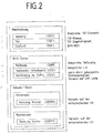
- FIG. 2 shows a summary of the interface description according to FIG. 1; the invariant data are only available once.
- the internal state SGZ (for switching devices on or off) is now required.
- the description according to FIG. 2 is directly assigned to the evaluation function of a basic element and is not visible from the outside.
- a basic element is always embedded between two nodes, which can be structured hierarchically.
- the data record contains information about the connection to the two surrounding nodes and is marked with SGVKK and SGRKK.
- SGVKK and SGRKK SGRKK
- the LVK lists are a special VK list. They describe the interface between basic elements. Their structure can be seen in FIG. 3.
- the LVK lists contain only one entry SGM and SGS, which is provided by the type 2 element of the relevant element group.
- SGV represents a list of the central nodes that are connected to the central node under consideration without going through a type 2 primitive.
- the LVK lists are managed by the evaluation functions of the basic elements of the relevant basic element group.
- the ZVK list is outside the basic element groups and contains SGM and SGS of each basic element that is permanently connected to the respective node, according to the current status of the description, individual basic elements. The above applies to SGV.
- the evaluation function of the basic elements is responsible.
- the internal state SGZ of the basic element is important here, i.e. the switching state of switching devices.
- the relevant activity of the evaluation function relates to the transfer of information from one VK list (LVK list, ZVK list) to another.
- the evaluation function comes into action when there is a change in one of the directly adjacent sales lists or when the state SGZ of the basic element has changed.
- the structure of the SK list is shown in Fig. 4. They contain the information SGM and SGS from the ZVK lists. The information to build up the SK lists is included in the ZVK lists under SGV. According to the SGV lists, the current ZVK lists of central nodes are summarized in SK lists by an evaluation function assigned to the SK lists.
- the structure picture acc. 7 shows basic elements of types 1 and 2 for a switchgear assembly, which are connected to one another by subnodes in the manner shown.
- a basic element GII2 in particular a circuit breaker, is connected to a local connection node LVK2.
- a basic element GI4 and a basic element GI5 are each connected to the local connection node LVK2.
- the letter G denotes the basic element, the number I or II the basic element type and the following number the Labelling.
- the basic element GI4 is connected to a central connection node ZVK2.
- the basic element GI5 is connected to a central connection node ZVK1.
- the basic element GII2 is also connected to a basic element GI6, since a local connection node LVK5 is connected to it, which is connected via a basic element GI7 to a connection node VK5.
- the central connection nodes ZVK1 and ZVK2 include connected via a basic element GI1 and GI2 to a local connection node LVK1, to which a branch with the series connection of a basic element GII1 and a basic element GI3 is connected. Furthermore, the central connecting nodes ZVK1 and ZVK2 are each connected via a basic element GI9 and GI8 to a local connecting node LVK3, which is connected via a basic element GII3 to a local connecting node LVK4, which is connected to the connecting node VK5 via a basic element GI10.
- the local connection node LVK5 originates connections to basic elements GI11 and GI12, which are still connected to connection nodes VK3 and VK4, which are each connected to the central connection nodes ZVK1 and ZVK2 via basic elements GI13 and GI14.
- the interfaces A and B of the basic elements GI1 to GI14 are each assigned data records DI1 to DI14 which have the scope shown in FIG. 1.
- the basic elements GII1 to GII3 are assigned data records DII1, DII2 and DII3, which likewise have the designations given in FIG. 2.
- the local connection nodes LVK1 to LVK5 are each assigned LVK lists LVK1-L to LVK5-L, each of which has the content shown in FIG. 3.
- VK lists VK3-L to VK5-L are assigned to the connection nodes VK3 to VKL5.
- the ZVK lists ZVK1-L and ZVK2-L are assigned to the central connection nodes ZVK1 and ZVK2.
- the current node list SK-L is formed from the lists ZVK1-L and VK3-L.
- the basic element of type 2 GII2 goes from the switching state "OFF" to "ON". It must now include the SGM and SGS information in its DII2 record for the Interface description must be entered because these properties are made accessible by switching it on. The entry is made identically at both interfaces.
- SGM and SGS are entered in the LVK list of the local node LVK2 (LVK list 2); SGV remains empty.
- GI4 goes from the switching state "OFF” to the switching state "ON.
- GI4 is switched off. Due to the switched element GII2 in the interface description B of GI5 (DGI5) are the specific data SGM and SGS of GII2, about which LVK list 2 (LVK2-L) entered. Due to the switch position change from "OFF” to "ON”, this information is transferred to the A side. Since the A side is fixed to VK1 and GI5 is switched on, the information " VK1 "under SGV in the LVK list 2 (LVK2-L). For GI4 the new entry in the LVK list 2 has no effect because GI4 is switched off.
- the next step is the ZVK list 1 (ZVK1-L It contains a list of all SGM and SGS of the basic elements permanently connected to this node. A connection to other ZVK lists only via basic elements of type 1 is not currently the case.
- the new entry on the A side of GI5, SGM and SGS from GI5 du The evaluation function of the basic element group has been added to ZVK list 1.
- the last step is to update the SK lists. Since there is no entry in the SGV of ZVK list 1 (ZVK1-L), there is now a power node list that is identical to ZVK list 1.
- the change in GI5 means that new data points are entered in a current node list. However, the number of power node lists has not changed.
- a structure can be set up for the evaluation using information technology methods, in which individual changes to the basic elements, this can affect both changes in the state and changes in the properties, are only of local importance. Furthermore, such a structure has the property of being separable and / or expandable at any point without the existing structure and evaluation functions having to be changed
- a structure can be created which reflects the properties of a switchgear with regard to the transmission of the electrical potential. Circuit changes in the real process can be mapped one-to-one on the internal structure.
- a busbar corresponds to a central reference point of the polarization direction of the basic elements.
- busbar image is based on the messages of the respective position of the switch contacts of the switchgear, so that there are no new requirements for the switchgear from this side.
- All busbar disconnectors are primarily evaluated. In the branches, where a coupling of busbars is possible due to their structure and integration in the switchgear, all switching devices that are in the possible coupling path are recorded.
- the relevant switching devices are divided into two classes and treated differently with regard to their evaluation: - class of disconnector (without earthing switch), correspond to the basic element type 1; - class of circuit breakers, correspond to the basic element type 2.
- a configuration calculation is triggered by an impending or successful change in the current switching status of one or more switching devices.
- the treatment of the change corresponds to the topology of the switchgear. This means that a change is only evaluated in the areas in which it is actually effective.
- the propagation of the change is checked until an SG element is reached that is directly connected to a busbar (central node ZVK).
- a connection node list (ZVK list) is maintained for each central node, which indicates which measuring points and circuit breakers currently belong to the corresponding busbar.
- the central node lists can be combined into larger structures via SG elements. If a change in the switch position affects the busbar, it is checked whether the ZVK list is connected to others or must now be connected. If this is the case, the current node list (SK list) is compiled from the corresponding ZVK lists.
- a power node list always contains at least the elements of a ZVK list. The complete assignment of the measuring points and circuit breakers to the protection zones can be found in it.
- a switchgear can have a maximum of as many power node lists as there are busbar sections.
- An interface description is defined for each basic element (switching device).
- the data record is constructed in such a way that no redundant information is held for the SG element.
- the description of the state of the SG element is also required.
- the reference to a rigid connection of central nodes is listed under "Connection to central nodes" (SGV).
- the essential information for the structure of the busbar image is contained in - "State" (SGZ) - 1/0 Meaning: Evaluate interface information yes / no ("configuration calculation necessary") as well as the useful data: - "Measuring point (SGM) identifier Meaning: Measuring point to be evaluated - "Command switching device” (SGS) - identifier Meaning: switching device to which the OFF command is to be given in the event of an error; corresponded directly with the measuring point to be evaluated. - "Connection central node” (SGVW) - reference Meaning: Reference to the list of busbars rigidly connected to this point (rigid: cannot be separated in the event of an error).
- step 5 “carry out configuration calculation”
- this evaluation is carried out by a method step 5.1 "calculate propagation” by specifying it under SGT. If local node lists have been changed and connections to central nodes are available from there, the ZVK list (s) and SK lists are changed accordingly in the "Update node” process step. The circuit breakers are monitored. If a circuit breaker fails, a replacement circuit breaker is selected in a method step 4. The corresponding change is taken into account in the information about the interface. So there is a hierarchical structure of the data groups. It is represented as follows: Art Assignment number Determining the content SG elements (basic elements) to every switching device plant-specific regardless of the switch status The basis are switch position messages, evaluation depends.
- switchgear type LVK list to every connection point between switching devices plant-specific are formed from the interface descriptions of the basic elements; general rule ZVK list to every busbar plant-specific per busbar is formed from the SG elements; general rule SK list to the switchgear depending on the respective switching status of the switchgear; is formed from the ZVK lists; general rule min .: none max .: number of busbars
- the busbar image is represented by the sum of the SK lists.
- the reference is based on a mimic diagram according to Fig. 5.
- a section of a switchgear is shown.
- In the coupling field E4, all switching devices are switched off.
- Two basic element groups are formed for this section of a switchgear.
- the current nodes SS1A and SS1B can still be handled as independent current nodes.
- the busbars SS1A and SS1B are rigidly coupled.
- the circuit breaker and the measuring point of the dome fields are bridged by the longitudinal separator and are therefore ineffective.
- the busbars SS1A and SS1B must now be treated as a current node.
- Circuit breakers in particular in gas-insulated switchgear, have signaling contacts that provide information on the extent to which the switchgear can perform switching operations. Of interest for protection are the messages that signal that an OFF switching can no longer be carried out. If this information is available, it can be taken into account when creating the busbar image. This means that it is checked whether the circuit breaker assigned to a measuring point is able to switch off a short circuit. If this is not the case, a replacement switch is selected from a configured list and, in the event of a fault, the OFF command is sent instead of the defective circuit breaker. The replacement switch will mostly be a switching device of a remote station. However, this means that there is a transmission channel for a take-away command there. A function is therefore available with which advanced switch failure protection can be implemented.
- FIG. 9 shows the structure of a basic element 6 from a variant data record part 7, an invariant data record part 8 and from an evaluation function part 9.
- the basic elements shown in FIG. 7, for example GI or GII, have the structure shown in FIG. 9.
Landscapes
- Engineering & Computer Science (AREA)
- Power Engineering (AREA)
- Supply And Distribution Of Alternating Current (AREA)
Applications Claiming Priority (2)
| Application Number | Priority Date | Filing Date | Title |
|---|---|---|---|
| DE3905114 | 1989-02-20 | ||
| DE3905114A DE3905114C2 (de) | 1989-02-20 | 1989-02-20 | Verfahren zum Erzeugen eines digitalen Abbilds einer mindestens eine Sammelschiene und Schaltgeräte enthaltenden Schaltanlage in einem elektrischen Energieverteilungsnetz |
Publications (1)
| Publication Number | Publication Date |
|---|---|
| EP0384307A1 true EP0384307A1 (fr) | 1990-08-29 |
Family
ID=6374492
Family Applications (1)
| Application Number | Title | Priority Date | Filing Date |
|---|---|---|---|
| EP90103002A Withdrawn EP0384307A1 (fr) | 1989-02-20 | 1990-02-16 | Procédé pour produire une image numérique d'installation de commutation comprenant au moins une barre omnibus et appareil de commutation dans un réseau de distribution d'énergie électrique |
Country Status (2)
| Country | Link |
|---|---|
| EP (1) | EP0384307A1 (fr) |
| DE (1) | DE3905114C2 (fr) |
Citations (3)
| Publication number | Priority date | Publication date | Assignee | Title |
|---|---|---|---|---|
| DE1465953A1 (de) * | 1964-10-16 | 1969-04-24 | Licentia Gmbh | Verfahren zum Abschalten einzelner Anlageteile aus einem Steuer-und/oder Verriegelungssystem einer aus mehreren Teilen bestehenden Gesamtanlage |
| DE2607622A1 (de) * | 1976-02-25 | 1977-09-01 | Bbc Brown Boveri & Cie | Verfahren zum schaltfehlerschutz in schaltanlagen |
| EP0166206A2 (fr) * | 1984-05-26 | 1986-01-02 | BBC Aktiengesellschaft Brown, Boveri & Cie. | Procédé et dispositif pour commander - avec protection contre erreur de commutation - une installation de distribution à panneaux de couplage multiples dans un réseau de distribution d'énergie électrique |
Family Cites Families (2)
| Publication number | Priority date | Publication date | Assignee | Title |
|---|---|---|---|---|
| CH671118A5 (fr) * | 1985-11-14 | 1989-07-31 | Bbc Brown Boveri & Cie | |
| DE3812072C3 (de) * | 1988-04-12 | 1993-09-30 | Licentia Gmbh | Verfahren zum schaltfehlergeschützten Betätigen der Schaltgeräte einer Schaltanlage |
-
1989
- 1989-02-20 DE DE3905114A patent/DE3905114C2/de not_active Expired - Fee Related
-
1990
- 1990-02-16 EP EP90103002A patent/EP0384307A1/fr not_active Withdrawn
Patent Citations (3)
| Publication number | Priority date | Publication date | Assignee | Title |
|---|---|---|---|---|
| DE1465953A1 (de) * | 1964-10-16 | 1969-04-24 | Licentia Gmbh | Verfahren zum Abschalten einzelner Anlageteile aus einem Steuer-und/oder Verriegelungssystem einer aus mehreren Teilen bestehenden Gesamtanlage |
| DE2607622A1 (de) * | 1976-02-25 | 1977-09-01 | Bbc Brown Boveri & Cie | Verfahren zum schaltfehlerschutz in schaltanlagen |
| EP0166206A2 (fr) * | 1984-05-26 | 1986-01-02 | BBC Aktiengesellschaft Brown, Boveri & Cie. | Procédé et dispositif pour commander - avec protection contre erreur de commutation - une installation de distribution à panneaux de couplage multiples dans un réseau de distribution d'énergie électrique |
Non-Patent Citations (1)
| Title |
|---|
| Revue Générale de l'electricité no. 9, Oktober 1988, Paris,France Seiten 39 - 41; R.Servet: "Controle-commande des postes: l'apport des réseau locaux" * |
Also Published As
| Publication number | Publication date |
|---|---|
| DE3905114C2 (de) | 1996-08-29 |
| DE3905114A1 (de) | 1990-08-23 |
Similar Documents
| Publication | Publication Date | Title |
|---|---|---|
| EP0224711B1 (fr) | Procédure d'actionnement protégé contre des erreurs de commutation des commutateurs d'une installation de commutation | |
| DE69717585T2 (de) | Elektronisches Energieverteilungssystem mit automatischen Schutzschaltern und entsprechendes Verfahren | |
| DE112016000102B4 (de) | Matrixverfahren zur automatischen Bestimmung der Logik des letzten Unterbrechers | |
| DE4442963A1 (de) | Verfahren zur Initialisierung und Aktualisierung eines Netzmodells | |
| DE3215177A1 (de) | Ueberwachungssystem fuer eine oder mehrere, gleichartig aufgebaute prozessstationen | |
| DE1512832A1 (de) | Anordnung zur Schaffung eines Teilbetriebs bei einem ausgefallenen,in Serie geschleiften Traegersystem | |
| WO2008134995A1 (fr) | Procédé et dispositif de détection d'un défaut dans un réseau d'alimentation électrique | |
| DE3688347T2 (de) | Leistungsversorgungseinrichtung fuer elektrische gleichstromeisenbahn. | |
| EP0503486A2 (fr) | Surveillance de ligne pour des signaux de la hiérarchie numérique synchrone | |
| EP0175120A1 (fr) | Dispositif de protection pour un réseau électrique | |
| EP1348970A1 (fr) | Test de validité des transformateurs de courant dans des sous-stations | |
| EP0170138A1 (fr) | Dispositif de protection pour réseau électrique | |
| EP0384307A1 (fr) | Procédé pour produire une image numérique d'installation de commutation comprenant au moins une barre omnibus et appareil de commutation dans un réseau de distribution d'énergie électrique | |
| EP0166206A2 (fr) | Procédé et dispositif pour commander - avec protection contre erreur de commutation - une installation de distribution à panneaux de couplage multiples dans un réseau de distribution d'énergie électrique | |
| EP3764311A1 (fr) | Procédé de planification d'un réseau de transmission d'énergie électrique, agencement de planification et produit programme informatique | |
| DE69325416T2 (de) | Lokales Netzwerk für ein Steuerungs- und Selbstüberwachungssystem eines elektronischen Gerätes | |
| EP0094697B1 (fr) | Procédé de limitation des courants de coupure des disjoncteurs dans une installation haute tension et l'application du procédé | |
| DE4027919A1 (de) | Verfahren und vorrichtung zum selektiven abtrennen von leitungsabschnitten in energieversorgungsnetzen | |
| EP0064094B1 (fr) | Dispositif de commutation électrique pour la représentation d'une installation de barres omnibus | |
| DE19722189A1 (de) | Verfahren zum Betrieb eines Ringbusses mit mehreren Teilnehmern sowie Vorrichtung zum Durchführen des Verfahrens | |
| DE69432397T2 (de) | Verfahren zur Prüfung der Datenintegrität und der Fehlerfreiheit von Verbindungsschaltungen in einem Rangierverteiler eines SDH-Netzwerks | |
| DE4137489C2 (de) | Verfahren und Einrichtung zum zuverlässigen Steuern von Schaltgeräten einer Schaltanlage | |
| DE2829839C2 (de) | Anordnung zur zeitmultiplexen Datenübertragung in einem Bus-System | |
| AT234781B (de) | Wegesuche und Auswahl von freien Verbindungswegen in einem beliebig viele Koppelstufen aufweisenden Feld von Koppelpunkten | |
| DE2542579A1 (de) | Koppelfeld fuer fernmeldevermittlungssysteme |
Legal Events
| Date | Code | Title | Description |
|---|---|---|---|
| PUAI | Public reference made under article 153(3) epc to a published international application that has entered the european phase |
Free format text: ORIGINAL CODE: 0009012 |
|
| AK | Designated contracting states |
Kind code of ref document: A1 Designated state(s): CH DE FR GB IT LI SE |
|
| 17P | Request for examination filed |
Effective date: 19900726 |
|
| 17Q | First examination report despatched |
Effective date: 19921008 |
|
| STAA | Information on the status of an ep patent application or granted ep patent |
Free format text: STATUS: THE APPLICATION IS DEEMED TO BE WITHDRAWN |
|
| 18D | Application deemed to be withdrawn |
Effective date: 19930219 |