EP0384343B1 - Tiroir avec paroi de séparation - Google Patents
Tiroir avec paroi de séparation Download PDFInfo
- Publication number
- EP0384343B1 EP0384343B1 EP90103127A EP90103127A EP0384343B1 EP 0384343 B1 EP0384343 B1 EP 0384343B1 EP 90103127 A EP90103127 A EP 90103127A EP 90103127 A EP90103127 A EP 90103127A EP 0384343 B1 EP0384343 B1 EP 0384343B1
- Authority
- EP
- European Patent Office
- Prior art keywords
- drawer
- partition
- projection
- face
- separation panel
- Prior art date
- Legal status (The legal status is an assumption and is not a legal conclusion. Google has not performed a legal analysis and makes no representation as to the accuracy of the status listed.)
- Expired - Lifetime
Links
- 238000000926 separation method Methods 0.000 title abstract 7
- 238000003780 insertion Methods 0.000 claims abstract description 15
- 230000037431 insertion Effects 0.000 claims abstract description 15
- 238000005192 partition Methods 0.000 claims description 43
- 238000006073 displacement reaction Methods 0.000 claims description 8
- 238000000605 extraction Methods 0.000 description 2
Images

Classifications
-
- A—HUMAN NECESSITIES
- A47—FURNITURE; DOMESTIC ARTICLES OR APPLIANCES; COFFEE MILLS; SPICE MILLS; SUCTION CLEANERS IN GENERAL
- A47B—TABLES; DESKS; OFFICE FURNITURE; CABINETS; DRAWERS; GENERAL DETAILS OF FURNITURE
- A47B88/00—Drawers for tables, cabinets or like furniture; Guides for drawers
- A47B88/90—Constructional details of drawers
- A47B88/969—Drawers having means for organising or sorting the content
- A47B88/994—Drawers having means for organising or sorting the content in the form of trays or inserts
-
- A—HUMAN NECESSITIES
- A47—FURNITURE; DOMESTIC ARTICLES OR APPLIANCES; COFFEE MILLS; SPICE MILLS; SUCTION CLEANERS IN GENERAL
- A47F—SPECIAL FURNITURE, FITTINGS, OR ACCESSORIES FOR SHOPS, STOREHOUSES, BARS, RESTAURANTS OR THE LIKE; PAYING COUNTERS
- A47F5/00—Show stands, hangers, or shelves characterised by their constructional features
- A47F5/0043—Show shelves
- A47F5/005—Partitions therefore
-
- A—HUMAN NECESSITIES
- A47—FURNITURE; DOMESTIC ARTICLES OR APPLIANCES; COFFEE MILLS; SPICE MILLS; SUCTION CLEANERS IN GENERAL
- A47B—TABLES; DESKS; OFFICE FURNITURE; CABINETS; DRAWERS; GENERAL DETAILS OF FURNITURE
- A47B88/00—Drawers for tables, cabinets or like furniture; Guides for drawers
- A47B88/90—Constructional details of drawers
- A47B88/969—Drawers having means for organising or sorting the content
- A47B88/975—Drawers having means for organising or sorting the content in the form of repositionable partition walls
Definitions
- the invention relates to a drawer with at least one insertable partition, which has a latch projecting beyond its end face, which can be connected and moved back to a drawer wall, and which is additionally mounted for longitudinal displacement on the partition, the longitudinal movement being deflected into a transverse movement and the Latch for the longitudinal movement has a lower shoulder which interacts with a stop of the drawer.
- the partition In known drawers of this type, the partition is locked in the sides and bottom of the drawer.
- the bolt that can be connected to the drawer wall must be operated by hand and moved transversely so that it engages in recesses in the drawer wall. Thus, two movements must be carried out when inserting the partition in the drawer. Once that Slide-in movement of the partition and secondly the transverse displacement of the bolt. This has the disadvantage that you need two hands or at least have to perform a very difficult one-handed movement.
- the lock can also be forgotten as it is not linked to the insertion movement.
- a drawer with a swivel support according to the preamble of claim 1 is known, wherein said swivel support can be inserted or removed with its two bearing journals in bearing recesses in the side walls.
- a molded part is slidably connected to the pivoted support in the area of the front edge of the swivel support, this displaceable molded part carrying the bearing journal.
- the bearing pin Through guide pin the molded part and elongated holes of the swivel support, one of which extends inclined to the side wall, the bearing pin can be moved together with the molded part approximately perpendicular to the side wall. The bearing pin is completely pulled out of the bearing recess. Likewise, the molded part with the journal can be moved towards the side wall until the journal engages completely in the bearing recess.
- the object of the present invention is therefore to develop a drawer of the type mentioned in such a way that the structure of the partition and the parts slidably mounted on it is simplified and yet an automatic, light and safe locking or unlocking when inserting and removing the Partition is guaranteed.
- a drawer with a partition in which, according to the invention, the extension is elastic and pre-bent inwards towards the partition and carries the latch, whereby it comes into contact with the partition during the longitudinal movement.
- the shoulder of the bolt touches the stop of the drawer, as a result of which the bolt moves laterally upwards along the partition and, since the longitudinal movement is deflected into a transverse movement, towards the drawer wall. At the end of the insertion it is then connected to the drawer wall.
- the locking takes place when the partition is pushed in, only a simple hand movement is necessary.
- the partition is also unlocked automatically. At the beginning of the pull-out movement, the bolt comes to rest with the edge of the recess in the drawer wall, as a result of which it can no longer be moved in the pull-out direction.
- the bolt When the partition is pulled out further, the bolt is guided along the partition to its bottom side, whereby due to the deflection of the longitudinal into a transverse movement, it moves transversely to the direction of extraction from the recess. At the end of the extraction movement, the bolt is outside the recess and the partition can be removed from the drawer.
- a particularly simple embodiment results if the bolt is designed as a knob and is fastened to a plate, the lower region of which is shaped as an extension in the direction of insertion of the partition.
- the elastic extension which is bent inward toward the partition, touches the stop of the drawer and is guided upwards along the partition as the insertion movement continues.
- the approach comes to rest on the partition and is pushed by this when you retract it towards the drawer wall.
- the bolt connected to the extension is moved transversely to the direction of insertion.
- the end face of the partition wall is advantageously provided as a guide for the attachment and a bolt projects into a slot provided on the partition wall and parallel to the end face, which is connected to the attachment that surrounds the end face. This results in a stable longitudinal displacement of the approach parallel to the end face of the partition.
- a further embodiment of the invention consists in that the extension has an inward recess at its end opposite to the direction of insertion of the partition to increase the elasticity.
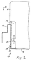
- a partition wall designed as a pendulum plate 16 is shown, which is designed as a plate.
- the pendulum plate 16 is in a drawer 17 with a bottom 18 and a side part 19 arranged. It has a cutout 22 directed towards its bottom side 21 on its end face 20.
- the end face 20 is enclosed by a plate 23.
- the plate 23 has a cross-sectionally U-shaped profile. With the plate 23, a pin 24 is connected, which is integrally formed with the plate 23 and protrudes into a slot 25 running parallel to the end face 20 of the pendulum plate 16.
- an attachment 27 which likewise has a profile which is U-shaped in cross section.
- the approach 27 is elastic and pre-bent to the pendulum plate 16.
- the bolt 28, which is designed as a knob, is attached to the extension 27.
- the projection 27 has, at its end opposite to the direction of insertion 26 of the pendulum plate, a semicircular opening 29 directed inwards towards the center of the pendulum plate.
- Fig. 1 shows the pendulum plate 16 with the approach 27 in the retracted position.
Landscapes
- Drawers Of Furniture (AREA)
- Containers And Packaging Bodies Having A Special Means To Remove Contents (AREA)
- Separation, Recovery Or Treatment Of Waste Materials Containing Plastics (AREA)
Claims (6)
- Tiroir comportant au moins une paroi de séparation à insérer qui présente un verrou (28) rétractable faisant saillie de sa face avant (20) et pouvant être relié à une paroi (19) du tiroir, qui, en outre, est monté sur la paroi de séparation de manière à pouvoir être déplacé longitudinalement, sachant que le mouvement longitudinal est dévié en un mouvement transversal et que le verrou (28) présente, pour le mouvement longitudinal, un prolongement (27) inférieur coopérant avec une butée du tiroir (17), caractérisé en ce que le prolongement (27) est élastique et précambré vers l'intérieur en direction de la paroi de séparation (16) et porte le verrou (28), sachant qu'il vient s'appliquer contre le paroi de séparation (16) lors du mouvement longitudinal.
- Tiroir comportant une paroi de séparation selon la revendication 1, caractérisé en ce que la face avant (20) de la paroi de séparation (16) est prévue en tant que glissière pour le prolongement (27).
- Tiroir comportant une paroi de séparation selon la revendication 2, caractérisé en ce qu'une goupille (24) reliée au prolongement (27) entourant la face avant (20) fait saillie dans une fente (25) parallèle à la face avant (20) et réalisée sur la paroi de séparation (16).
- Tiroir comportant une paroi de séparation selon l'une des revendications 1 à 3, caractérisé en ce que le prolongement (27) présente à son extrémité opposée au sens d'insertion (26) de la paroi de séparation (16) un évidement (29) tourné vers l'intérieur pour augmenter l'élasticité.
- Tiroir comportant une paroi de séparation selon l'une ou plusieurs des revendications précédentes, caractérisé en ce que le prolongement (27) avec le verrou (28) tiré s'étend sur le fond (21) de la paroi de séparation (16) sur une longueur correspondant à l'amplitude du mouvement et en ce que la butée est le fond (18) du tiroir (17).
- Tiroir selon l'une ou plusieurs des revendications précédentes, caractérisé en ce que le prolongement (27) est réalisé à l'extrémité inférieure d'une plaque (23) qui présente une section en forme de U et en ce que la paroi de séparation (16) est disposée entre ses bras.
Priority Applications (1)
| Application Number | Priority Date | Filing Date | Title |
|---|---|---|---|
| AT90103127T ATE98099T1 (de) | 1989-02-24 | 1990-02-19 | Schublade mit trennwand. |
Applications Claiming Priority (2)
| Application Number | Priority Date | Filing Date | Title |
|---|---|---|---|
| DE8902225U | 1989-02-24 | ||
| DE8902225U DE8902225U1 (de) | 1989-02-24 | 1989-02-24 | Schublade mit Trennwand |
Publications (3)
| Publication Number | Publication Date |
|---|---|
| EP0384343A2 EP0384343A2 (fr) | 1990-08-29 |
| EP0384343A3 EP0384343A3 (en) | 1990-11-07 |
| EP0384343B1 true EP0384343B1 (fr) | 1993-12-08 |
Family
ID=6836399
Family Applications (1)
| Application Number | Title | Priority Date | Filing Date |
|---|---|---|---|
| EP90103127A Expired - Lifetime EP0384343B1 (fr) | 1989-02-24 | 1990-02-19 | Tiroir avec paroi de séparation |
Country Status (4)
| Country | Link |
|---|---|
| EP (1) | EP0384343B1 (fr) |
| AT (1) | ATE98099T1 (fr) |
| DE (2) | DE8902225U1 (fr) |
| ES (1) | ES2049356T3 (fr) |
Families Citing this family (7)
| Publication number | Priority date | Publication date | Assignee | Title |
|---|---|---|---|---|
| DE4237968C2 (de) * | 1992-10-26 | 1996-05-30 | Grass Ag | Trennwandelement zur Schubladeneinteilung von Schubladen |
| DE9315972U1 (de) * | 1993-10-20 | 1995-02-16 | Fa. Gustav Ziehl, 50996 Köln | Schublade und Zwischensteg für diese |
| DE9419588U1 (de) * | 1994-12-07 | 1995-02-02 | Häfele GmbH & Co, 72202 Nagold | In eine Schublade einsetzbare Zwischenwand |
| DE9419587U1 (de) * | 1994-12-07 | 1995-02-02 | Häfele GmbH & Co, 72202 Nagold | Zwischenwand insbesondere für Schubladen |
| DE29922006U1 (de) * | 1999-12-15 | 2001-01-04 | GRASS GmbH, Höchst | Verbindungselement für Trennwände zur Facheinteilung einer Schublade |
| DE202004010776U1 (de) * | 2004-07-08 | 2005-07-28 | Grass Gmbh | Schublade mit Facheinteilungen |
| DE202009004810U1 (de) * | 2009-05-12 | 2010-09-23 | Paul Hettich Gmbh & Co. Kg | Schubkasten |
Family Cites Families (2)
| Publication number | Priority date | Publication date | Assignee | Title |
|---|---|---|---|---|
| DE8617604U1 (de) * | 1986-07-02 | 1986-08-14 | Paul Hettich GmbH & Co, 4983 Kirchlengern | Schubkasten |
| DE3701751A1 (de) * | 1987-01-22 | 1988-08-04 | Hettich Paul Gmbh & Co | Schubkasten mit mindestens einer schwenkstuetze |
-
1989
- 1989-02-24 DE DE8902225U patent/DE8902225U1/de not_active Expired
-
1990
- 1990-02-19 DE DE90103127T patent/DE59003730D1/de not_active Expired - Fee Related
- 1990-02-19 ES ES90103127T patent/ES2049356T3/es not_active Expired - Fee Related
- 1990-02-19 EP EP90103127A patent/EP0384343B1/fr not_active Expired - Lifetime
- 1990-02-19 AT AT90103127T patent/ATE98099T1/de active
Also Published As
| Publication number | Publication date |
|---|---|
| ATE98099T1 (de) | 1993-12-15 |
| EP0384343A2 (fr) | 1990-08-29 |
| EP0384343A3 (en) | 1990-11-07 |
| DE8902225U1 (de) | 1989-04-06 |
| DE59003730D1 (de) | 1994-01-20 |
| ES2049356T3 (es) | 1994-04-16 |
Similar Documents
| Publication | Publication Date | Title |
|---|---|---|
| EP0606564B1 (fr) | Dispositif de réglage de l'orientation de tiroirs et similaires | |
| DE69933228T2 (de) | System und mechanismus zum verriegeln von akten | |
| EP0580075B1 (fr) | Dispositif automatique d'emboîtement pour glissières de tiroirs | |
| DE3628438C1 (de) | Handgriff fuer Toepfe oder dergleichen | |
| EP0743032A2 (fr) | Glissière pour tiroir | |
| DE102014113954B4 (de) | Verstelleinrichtung | |
| EP1036526A1 (fr) | Dispositif pour la stabilisation du comportement d'un tiroir déplaçable dans un corps de meuble | |
| DD298734A5 (de) | Fuehrung fuer einen auszug, einen schubkasten od. dgl. | |
| DE2852230A1 (de) | Ausziehfuehrung fuer schubladen u.dgl. | |
| EP1093735B1 (fr) | Glissière pour guidage de tiroirs avec dispositif de fixation et de réglage en hauteur | |
| EP0384343B1 (fr) | Tiroir avec paroi de séparation | |
| DE3727200A1 (de) | Sender/antennen-feld | |
| WO2006106029A1 (fr) | Glissiere telescopique destinee a un element de meuble dispose de façon mobile dans un corps de meuble | |
| EP0140329A2 (fr) | Rail pour rideau | |
| DE8304739U1 (de) | Eckumlenkung eines in hinterschnittene profilnuten oder rahmenprofile von fenster und tueren aus metall, kunststoff od. dgl. einsetzbaren treibstangenverschlusses | |
| AT522450A4 (de) | Möbel | |
| EP0552500A1 (fr) | Dispositif de guidage | |
| DE19538101A1 (de) | Auszugführung | |
| EP0267508B1 (fr) | Support d'essuie-mains | |
| EP0639687B1 (fr) | Glissière | |
| DE102021108249A1 (de) | Koppelelement, Schließsystem und Möbel | |
| DE7520486U (de) | Ausstellvorrichtung für aus Metalloder Kunststoffprofilen zusammengesetzte Fenster und Türen o.dgl | |
| DE10043723A1 (de) | Schaltschrank mit verriegelbaren Einschüben | |
| AT392725B (de) | Moebelteil mit einer schubladenfuehrung | |
| DE3445234C2 (fr) |
Legal Events
| Date | Code | Title | Description |
|---|---|---|---|
| PUAI | Public reference made under article 153(3) epc to a published international application that has entered the european phase |
Free format text: ORIGINAL CODE: 0009012 |
|
| AK | Designated contracting states |
Kind code of ref document: A2 Designated state(s): AT CH DE ES FR GB IT LI NL |
|
| PUAL | Search report despatched |
Free format text: ORIGINAL CODE: 0009013 |
|
| AK | Designated contracting states |
Kind code of ref document: A3 Designated state(s): AT CH DE ES FR GB IT LI NL |
|
| 17P | Request for examination filed |
Effective date: 19910330 |
|
| 17Q | First examination report despatched |
Effective date: 19920407 |
|
| GRAA | (expected) grant |
Free format text: ORIGINAL CODE: 0009210 |
|
| AK | Designated contracting states |
Kind code of ref document: B1 Designated state(s): AT CH DE ES FR GB IT LI NL |
|
| REF | Corresponds to: |
Ref document number: 98099 Country of ref document: AT Date of ref document: 19931215 Kind code of ref document: T |
|
| REF | Corresponds to: |
Ref document number: 59003730 Country of ref document: DE Date of ref document: 19940120 |
|
| ET | Fr: translation filed | ||
| GBT | Gb: translation of ep patent filed (gb section 77(6)(a)/1977) |
Effective date: 19940105 |
|
| ITF | It: translation for a ep patent filed | ||
| REG | Reference to a national code |
Ref country code: ES Ref legal event code: FG2A Ref document number: 2049356 Country of ref document: ES Kind code of ref document: T3 |
|
| PLBE | No opposition filed within time limit |
Free format text: ORIGINAL CODE: 0009261 |
|
| STAA | Information on the status of an ep patent application or granted ep patent |
Free format text: STATUS: NO OPPOSITION FILED WITHIN TIME LIMIT |
|
| 26N | No opposition filed | ||
| PGFP | Annual fee paid to national office [announced via postgrant information from national office to epo] |
Ref country code: FR Payment date: 19980115 Year of fee payment: 9 |
|
| PGFP | Annual fee paid to national office [announced via postgrant information from national office to epo] |
Ref country code: GB Payment date: 19980119 Year of fee payment: 9 |
|
| PGFP | Annual fee paid to national office [announced via postgrant information from national office to epo] |
Ref country code: AT Payment date: 19980127 Year of fee payment: 9 |
|
| PGFP | Annual fee paid to national office [announced via postgrant information from national office to epo] |
Ref country code: ES Payment date: 19980210 Year of fee payment: 9 |
|
| PG25 | Lapsed in a contracting state [announced via postgrant information from national office to epo] |
Ref country code: GB Free format text: LAPSE BECAUSE OF NON-PAYMENT OF DUE FEES Effective date: 19990219 Ref country code: AT Free format text: LAPSE BECAUSE OF NON-PAYMENT OF DUE FEES Effective date: 19990219 |
|
| PG25 | Lapsed in a contracting state [announced via postgrant information from national office to epo] |
Ref country code: ES Free format text: LAPSE BECAUSE OF NON-PAYMENT OF DUE FEES Effective date: 19990220 |
|
| GBPC | Gb: european patent ceased through non-payment of renewal fee |
Effective date: 19990219 |
|
| PG25 | Lapsed in a contracting state [announced via postgrant information from national office to epo] |
Ref country code: FR Free format text: LAPSE BECAUSE OF NON-PAYMENT OF DUE FEES Effective date: 19991029 |
|
| REG | Reference to a national code |
Ref country code: FR Ref legal event code: ST |
|
| PGFP | Annual fee paid to national office [announced via postgrant information from national office to epo] |
Ref country code: CH Payment date: 20010115 Year of fee payment: 12 |
|
| PGFP | Annual fee paid to national office [announced via postgrant information from national office to epo] |
Ref country code: NL Payment date: 20010227 Year of fee payment: 12 |
|
| REG | Reference to a national code |
Ref country code: ES Ref legal event code: FD2A Effective date: 20010910 |
|
| PG25 | Lapsed in a contracting state [announced via postgrant information from national office to epo] |
Ref country code: LI Free format text: LAPSE BECAUSE OF NON-PAYMENT OF DUE FEES Effective date: 20020228 Ref country code: CH Free format text: LAPSE BECAUSE OF NON-PAYMENT OF DUE FEES Effective date: 20020228 |
|
| PG25 | Lapsed in a contracting state [announced via postgrant information from national office to epo] |
Ref country code: NL Free format text: LAPSE BECAUSE OF NON-PAYMENT OF DUE FEES Effective date: 20020901 |
|
| REG | Reference to a national code |
Ref country code: CH Ref legal event code: PL |
|
| NLV4 | Nl: lapsed or anulled due to non-payment of the annual fee |
Effective date: 20020901 |
|
| PGFP | Annual fee paid to national office [announced via postgrant information from national office to epo] |
Ref country code: DE Payment date: 20041229 Year of fee payment: 16 |
|
| PG25 | Lapsed in a contracting state [announced via postgrant information from national office to epo] |
Ref country code: IT Free format text: LAPSE BECAUSE OF NON-PAYMENT OF DUE FEES;WARNING: LAPSES OF ITALIAN PATENTS WITH EFFECTIVE DATE BEFORE 2007 MAY HAVE OCCURRED AT ANY TIME BEFORE 2007. THE CORRECT EFFECTIVE DATE MAY BE DIFFERENT FROM THE ONE RECORDED. Effective date: 20050219 |
|
| PG25 | Lapsed in a contracting state [announced via postgrant information from national office to epo] |
Ref country code: DE Free format text: LAPSE BECAUSE OF NON-PAYMENT OF DUE FEES Effective date: 20060901 |