EP0639687B1 - Glissière - Google Patents
Glissière Download PDFInfo
- Publication number
- EP0639687B1 EP0639687B1 EP94111611A EP94111611A EP0639687B1 EP 0639687 B1 EP0639687 B1 EP 0639687B1 EP 94111611 A EP94111611 A EP 94111611A EP 94111611 A EP94111611 A EP 94111611A EP 0639687 B1 EP0639687 B1 EP 0639687B1
- Authority
- EP
- European Patent Office
- Prior art keywords
- pull
- guide means
- locking
- out guide
- holder
- Prior art date
- Legal status (The legal status is an assumption and is not a legal conclusion. Google has not performed a legal analysis and makes no representation as to the accuracy of the status listed.)
- Expired - Lifetime
Links
- 125000006850 spacer group Chemical group 0.000 claims description 13
- 230000000284 resting effect Effects 0.000 claims 1
- 239000000284 extract Substances 0.000 description 21
- 210000002105 tongue Anatomy 0.000 description 19
- 230000000903 blocking effect Effects 0.000 description 16
- 239000000969 carrier Substances 0.000 description 4
- 238000004519 manufacturing process Methods 0.000 description 4
- 230000002730 additional effect Effects 0.000 description 1
- 230000005484 gravity Effects 0.000 description 1
- 238000003801 milling Methods 0.000 description 1
- 238000005096 rolling process Methods 0.000 description 1
- 239000007787 solid Substances 0.000 description 1
Images


Classifications
-
- E—FIXED CONSTRUCTIONS
- E05—LOCKS; KEYS; WINDOW OR DOOR FITTINGS; SAFES
- E05C—BOLTS OR FASTENING DEVICES FOR WINGS, SPECIALLY FOR DOORS OR WINDOWS
- E05C19/00—Other devices specially designed for securing wings, e.g. with suction cups
- E05C19/06—Other devices specially designed for securing wings, e.g. with suction cups in which the securing part if formed or carried by a spring and moves only by distortion of the spring, e.g. snaps
-
- E—FIXED CONSTRUCTIONS
- E05—LOCKS; KEYS; WINDOW OR DOOR FITTINGS; SAFES
- E05B—LOCKS; ACCESSORIES THEREFOR; HANDCUFFS
- E05B65/00—Locks or fastenings for special use
- E05B65/46—Locks or fastenings for special use for drawers
- E05B65/462—Locks or fastenings for special use for drawers for two or more drawers
- E05B65/463—Drawer interlock or anti-tilt mechanisms, i.e. when one drawer is open, at least one of the remaining drawers is locked
Definitions
- the invention relates to a pull-out guide for from Extendable body pull-outs, including one on the body side Guide rail and a pull-out guide rail as well as two brackets that can be mounted on the body, which the Wear a guide rail on the cabinet side.
- Such pull-out guides are for example from the European patent application 0 367 274 known.
- This locking mechanism is preferably used to either all extracts to lock or when pulling out a pull-out to block other extracts from being pulled out.
- the invention is therefore based on the object To improve drawer management of the generic type in such a way that simplifies the assembly of the locking mechanism becomes.
- This task is at the beginning of an excerpt described type according to the invention solved in that a front straps a locking bar in a die Excerpts releasing position and one of the extracts blocking position defined trained positioning is and that on a front carrier a locking device is provided, which is based on a Moving locking element of the locking bar in one of the Positions of the locking bar can be locked.
- the locking device is designed so that by acting on the locking bar the locking element can be locked into the locking device or can be disengaged.
- the latching element in the locking position of the locking bar in the locking device snaps into place. This allows the locking bar to be arranged so that it acts by gravity is in the releasing position and only by lifting from the releasing position to the blocking position is movable.
- the blocking is advantageous Position an upper position of the locking bar.
- the locking tongues are expediently designed so that each of the locking tongues has a locking lug, preferably the locking lugs of the two locking tongues are facing each other.
- the latching element could be of various types and Be trained.
- the locking element is a Locking cam is which on the locking tongue or the locking tongues can be moved past.
- the carrier is a carrier-side limiting element has, which with a locking bar side Limiting element one of the positions of the locking bar Are defined.
- the support-side limiting element is a support for the striker-side limiting element, because this is a structurally extremely simple and therefore represents inexpensive to manufacture solution.
- the locking element is as Snap cams formed.
- the support can be in various types and on the carrier Way are formed. It is particularly useful if the support is formed by a web on the carrier.
- the locking device is integrally formed on the carrier is. This is the simplest and especially the cheapest Type of manufacture of the locking device together with the carrier.
- the support is in one piece is molded onto the carrier. This production of the support too is precise on the one hand and also on the other hand extremely inexpensive.
- the carrier has a Guide channel for the locking bar includes.
- the guide channel facing the body has open side, so that from this side of the Guide channel the locking bar in the carrier easily can be used.
- the locking device could in principle on one of the Guide channel arranged completely independent point on the carrier be.
- a latching cam is provided as a latching element, one sees advantageous embodiment that the carrier has a cam channel for the locking cam, so that also the locking cam is movable in the carrier.
- the guide channel and the cam channel are connected to one another, in particular a connection between the two via a free space between the two.
- the free space can expediently be designed such that that an edge of the same the support for the locking cam forms.
- the latching device is preferably in the free space arranged between the guide channel and the cam channel.
- an advantageous embodiment provides that the locking device between a body contact surface of the Carrier and a guide rail receptacle of the carrier lies.
- the locking device With regard to the arrangement of the locking device relative to a possibility of fastening the carrier to the body it is preferably provided that the locking device is arranged between two dowels of the carrier.
- the guide channel is preferably located between two dowels of the carrier.
- the Cam part is arranged in the spacer body of the carrier.
- the task at the outset is also used for a body with several led through pull-out guides Extracts and with a between a releasing and a locking position sliding locking bar solved according to the invention to lock the extracts, that at least one of the pull-out guides according to one or several of the above-mentioned embodiments is trained.
- each extract is still is also provided with a backdrop element with which the locking bar can be operated, and thus the Possibility to pull out an extract from the Corpus to lock the other pull-outs against pulling out.
- the cabinet-side guide rail can be firmly connected to the carriers.
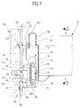
- a body 10 according to the invention comprises several extracts, of which only an extract, namely a drawer 12, is shown.
- the drawer 12 is by two on both sides of the drawer 12 between it and the body 10 arranged pull-out guides 14, each of the Pull-out guides 14 have a pull-out guide rail 16 and a body side guide rail 18 which displaceable relative to each other and for this purpose via rolling elements 20 are stored together.
- the pull-out guide rail 16 firmly connected to the drawer 12 via a bracket 22.
- the body-side guide rail 18 is in turn from two in a longitudinal direction 24 of the guide rails 16, 18 spaced apart supports 26 on the Body kept, being in the illustrated embodiment the carrier 26 the body-side guide rail 18 with a lower guide body 28 and an upper one Guide body 30 overlaps C-shaped and thus the Body-side guide rail 18 in the longitudinal direction 24 slidably guides while the guide body 28 and 30th the guide rail 18 precisely across the longitudinal direction 24 to lead.
- the cabinet side Guide rail 18 can be reached on the guide body 28 this is provided in the middle with a curvature 32 on which the body-side guide rail 18 linear or point-shaped lies on.
- the two guide bodies 28 and 30 are marked by a whole with 34 spacers at a distance of an inside 36 of the body 10 held so that the entire body-side guide rail 18 at a distance of the inside 36 of the body 10 extends.
- the spacer 34 is in turn with two dowels 38 in the body, for example in a bearing the inside 36 Side wall 40, anchored.
- a Entire with 42 designated locking bar On the inside 36 of the side wall 40 is a Entire with 42 designated locking bar, which in essentially parallel and at a distance from a front 44 of the body 10 extends in the vertical direction and for each of the drawers 12 carries a locking pin 46.
- the Locking bar 42 is in its longitudinal direction 48, which approximately vertical in body 10 and unguided in right Angle to the longitudinal direction 24 runs, movable, the Locking bar 42 with its outside 50 on the inside 36 of the side wall 40 abuts and the locking pin 46 from an inside 52 of the locking bar to the inside of the Body 10 protrudes towards the extract 12.
- Link element held On the extract 12 is a whole designated 60 Link element held, which has a locking surface 62nd carries, and one of a front front 64 of the drawer 12 seen from increasing length in the longitudinal direction upward opening / closing slide 66, which by a lower link surface 68 and an upper link surface 70 is limited.
- the backdrop 66 has a front opening 72, which is below the blocking surface 62 and a rear Mouth opening 74, which is at approximately the same height as the blocking surface 62 lies.
- the locking pin 46 is pulled through in FIG. 2 drawn, the excerpt 12 releasing position, so it stands in front of the mouth opening 72 and is pulled out of the pull-out 12 through the closing / opening slide 66 raised, so that at the end of the same amount of Mouth opening 74 is.
- the locking pin 46 Since the mouth 74 is at the same level as that Locking surface 62, the locking pin 46 is in the area of Mouth opening 72 can then be in a blocking position however, no longer block extract 12 because it already does was pulled out.
- the closing bar 42 now carries for each of the pullouts 12 the body 10 a locking pin on the locking bar 42 sits and by moving the locking bar 42 in the longitudinal direction 48 either from the releasing Position in the locking position or vice versa is.
- a lock 80 which for example is arranged in the uppermost drawer 82 of the body 10
- the locking bar 42 in its longitudinal direction 48 from the releasing position, i.e. the position in which all Locking pins 46 are in the releasing position, in their blocking position, i.e. in the position in which all locking pins 46 pulling out the pull-outs 12 lock, moved upwards, all extracts are 12 blocked.
- the same is moving the locking bar 42 from the blocking position to the releasing position possible below, in which any of the extracts 12 can be pulled out.
- the closing / opening gate track 66 serves to prevent that several of the extracts 12 from the body 10 be pulled out. This causes that at Pull out one of the drawers 12 and the other drawers 12 are locked.
- the locking bar 42 transverse to their longitudinal direction 48 through the front Carrier 26 of the pull-out guides.
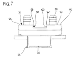
- the carrier 26 is thereby, as shown in FIGS. 4 to 7, with a Guide channel 90 provided which to the inside 36 of the Sidewall 40 is open and by edges 92 one Back 93 of the carrier 26 is limited.
- the edges 92 opposite is the guide channel 90 through across Longitudinal direction 48 transverse walls 94 and 96 limited, and further the guide channel 90 is through two longitudinal walls 98 and 100 limited, which is parallel to the longitudinal direction 48 run.
- the guide channel 90 is in the spacer 34 arranged.
- Pull-out guides 14 of the pull-outs 12 are designed as locking cams Locking element 106, which is in the area of the free space 102 from the inside 52 of the closing strip 42 protrudes, passes through the free space 102 and into the cam channel 104 engages.
- the locking cam 106 is one along Cam track movable, from a lower one, always solid position, which of the releasing Position of the locking bar corresponds to an upper, position shown in dashed lines, which of the locking position of the locking bar 42 corresponds.
- the Expansion of the cam track 108 in the longitudinal direction corresponds hence the path that is required to achieve the Locking pins 46 from the releasing to the locking Position and vice versa.
- the free space 102 is vertically downward through a web 110, which one with the space 102 facing Edge of a support 112 for the locking cam 106 forms so that the locking cam 106 on the web 110 in his lower position rests, which in turn the releasing Position of the locking bar 42 corresponds.
- the web 110 is arranged so that it is on the one hand the transverse wall 96 forms and the guide channel 90 of the Cam channel 104 in a lower region of the spacer 34 separates from each other. It is also the support 112 forming upper edge of the web is concave, wherein the lowest point is in the middle of cam track 108 and thus the support 112 the locking cam 106 in its centered lower position to the cam track 108. So that the locking bar 42 in the Guide channel 90 also centered in the middle.
- the support 112 together with the locking cam 106 a lower limit for the mobility of the Locking bar 42 represents and defines in the longitudinal direction 48 at the same time the releasing position of all of them Locking pins 46.
- Another limitation of the Movability of the locking bar 42 in the longitudinal direction 48 downward is unnecessary and is thus the inventive No solution.
- Locking device 114 which has two locking tongues 116 and 118, which facing latching lugs 120th and 122 that protrude toward cam track 108 and in each direction of movement of the cam track 108 have acting run-up bevels 124 and 126, against each other are inclined and in the area of a highest point 128 into each other approximately in the middle of the locking lugs 120, 122 pass over.
- the locking tongues 116 and 118 are in terms of their Spring action dimensioned so that an additional action on the locking bar 42 of the locking cams 106 through the bevels 124 and the locking tongues 116 and 118 die entire locking bar 42 with all of its locking pins 46 holds in the blocking position.
- the resilient locking tongues 116 and 118 extend preferably parallel to the longitudinal direction 48 on both sides of the Cam track 108 and are with a locking lugs 120, 122nd opposite foot area 130, 132 on a the Transverse wall 94 carrying transverse web 134 of the spacer 34 molded in one piece so that the two locking tongues 116 and 118 comprise an approximately U-shaped recess 136, which in the area of the locking lugs 120, 122 to the support 112 is open.
- the locking tongues 116, 118 are preferably in the same level as the web 110 and thus between the Guide channel 90 and the cam channel 104.
- those shown in the invention Carrier all parts, i.e. the guide bodies 28, 30, the spacer 34 together with the web 110, the crossbar 134 and the locking tongues 116, 118 and the dowels 38 made of a single plastic part.
- the releasing position is thus for the support 112 the locking bar 42 with all locking pins 46 exactly defined and formed by the locking device 114 together with the locking cam 106 the locking position, wherein the locking cam 106 in the locking device 114 through a force acting on the locking bar 42 on the Lock 80 or the closing / opening gate 66 can be snapped into place is or also by a force the locking bar 42 through the lock 80 or the Closing / opening gate 66 can be disengaged.
Landscapes
- Engineering & Computer Science (AREA)
- Mechanical Engineering (AREA)
- Drawers Of Furniture (AREA)
Claims (29)
- Guidage de tiroir pour des tiroirs (12) que l'on peut sortir hors d'une ossature (10), comportant un rail de guidage (18) situé du côté de l'ossature et un rail de guidage (16) situé du côté du tiroir ainsi que deux supports (26) qui peuvent se monter sur l'ossature et portent les rails de guidage (8) situés du côté de l'ossature,
caractérisé
par le fait qu'est prévu un support avant (26) qui positionne, de façon définie, une tringle de verrouillage (42) dans une position qui déverrouille les tiroirs (12) et dans une position qui verrouille les tiroirs (12), et que sur un support avant (26) est prévu un dispositif de crantage (114) qui, dans l'une des positions de la tringle de verrouillage (42), peut se cranter avec un élément de crantage (106), mobile sur un chemin (108), de la tringle de verrouillage (42). - Guidage de tiroir selon la revendication 1, caractérisé par le fait que le dispositif de crantage (114) est conçu de façon qu'en agissant sur la tringle de verrouillage (42) on puisse cranter l'élément de crantage (106) dans le dispositif de crantage (114) ou l'en déchanter.
- Guidage de tiroir selon l'une des revendications précédentes, caractérisé par le fait que l'élément de crantage (106) peut se cranter dans le dispositif de crantage (114) dans une position de verrouillage de la tringle de verrouillage (42).
- Guidage de tiroir selon l'une des revendications précédentes. caractérisé par le fait que le dispositif de crantage (114) comporte une languette de crantage (116, 118) qui collabore avec l'élément de crantage (106).
- Guidage de tiroir selon la revendication 4, caractérisé par le fait que la languette de crantagc (116, 118) présente un talon de crantage (120, 122).
- Guidage de tiroir selon l'une des revendications précédentes, caractérisé par le fait que l'élément de crantage est un ergot de crantage (106).
- Guidage de tiroir selon l'une des revendications précédentes, caractérisé par le fait que l'une des positions de la tringle de verrouillage (42) est définie par la position de l'élément de crantage (106) cranté dans le dispositif de crantage (114).
- Guidage de tiroir selon l'une des revendications précédentes, caractérisé par le fait que le support (26) comporte un élément de limitation (112) qui est situé du côté du support et qui, avec un élément de limitation (116), situé du côté de la tringle de verrouillage, définit l'une des positions de la tringle de verrouillage (42).
- Guidage de tiroir selon la revendication 8, caractérisé par le fait que l'élément de limitation situé du côté du support présente un appui (112) pour l'élément de limitation (106) situé du côté de la tringle de verrouillage.
- Guidage de tiroir selon la revendication 8 ou 9, caractérisé par le fait que l'élément de limitation situé du côté la tringle de verrouillage est formée par l'élément de crantage (106).
- Guidage de tiroir selon la revendication 9 ou 10, caractérisé par le fait que l'appui (112) est formé par une barrette (110) prévue sur le support (26).
- Guidage de tiroir selon l'une des revendications précédentes, caractérisé par le fait que le dispositif de crantage (114) est venu de moulage, d'une seule pièce, sur le support (26),
- Guidage de tiroir selon l'une des revendications précédentes, caractérisé par le fait que l'appui (112) est venu de moulage, d'une seule pièce, sur le support (26).
- Guidage de tiroir selon la revendication 12 ou 13, caractérisé par le fait que le support (26) est conçu sous forme d'une pièce de plastique d'une seule pièce.
- Guidagc de tiroir selon l'une des revendications précédentes, caractérisé par le fait que le support (26) comporte un canal de guidage (90) pour la tringle de verrouillage (42).
- Guidage de tiroir selon la revendication 15, caractérisé par le fait que le canal de guidage (90) présente un côté ouvert (92) orienté vers l'ossature (10).
- Guidage de tiroir selon la revendication 16, caractérisé par le fait que le canal de guidage (90) guide la tringle de verrouillage (42) en l'appuyant contre l'ossature (10).
- Guidage de tiroir selon la revendication 16 ou 17, caractérisé par le fait que le dispositif de crantage (114) se limite au côté du canal de guidage (90) opposé au côté ouvert.
- Guidage de tiroir selon l'une des revendications 16 à 18, caractérisé par le fait que l'appui (112) se limite au côté du canal de guidage (90) opposé au côté ouvert.
- Guidage de tiroir selon l'une des revendications 6 à 19, caractérisé par le fait que le support (26) présente un canal d'ergot (104) pour l'ergot de crantage (106).
- Guidage de tiroir selon la revendication 20, caractérisé par le fait que le canal de guidage (90) et le canal d'ergot (104) sont reliés l'un à l'autre.
- Guidage de tiroir selon l'une des revendications précédentes, caractérisé par le fait que le dispositif de crantage (114) se situe entre une surface (93) du support (26) d'appui contre l'ossature et un réceptacle (28, 30) du rail de guidage.
- Guidage de tiroir selon la revendication 22, caractérisé par le fait que le dispositif de crantage (114) est disposé dans un écarteur (34) du support (26).
- Guidage de tiroir selon l'une des revendications précédentes, caractérisé par le fait que le dispositif de crantage est situé entre deux chevilles (38) du support (26).
- Guidage de tiroir selon l'une des revendications 15 à 24, caractérisé par le fait que le canal de guidage (90) est situé dans un écarteur (34) du support (26).
- Guidage de tiroir selon la revendication 25, caractérisé par le fait que le canal de guidage (90) est situé entre deux chevilles (38) du support (26).
- Guidage de tiroir selon l'une des revendications 20 à 26, caractérisé par le fait que le canal d'ergot (104) est situé dans l'écarteur (34) du support (26).
- Ossature contenant plusieurs tiroirs guidés par des guidages de tiroir et une tringle de verrouillage, qui peut coulisser entre une position de déverrouillage et une position de verrouillage, pour verrouiller les tiroirs, caractérisé par le fait qu'au moins un guidage de tiroir (14) d'un tiroir (12) est conçu selon l'une des revendications 1 à 27.
- Ossature selon la revendication 28, caractérisé par le fait que chaque tiroir (12) est muni d'un élément formant coulisse (60) pour manoeuvrer la tringle de verrouillage (42).
Applications Claiming Priority (2)
| Application Number | Priority Date | Filing Date | Title |
|---|---|---|---|
| DE4327688 | 1993-08-18 | ||
| DE4327688A DE4327688A1 (de) | 1993-08-18 | 1993-08-18 | Auszugführung |
Publications (2)
| Publication Number | Publication Date |
|---|---|
| EP0639687A1 EP0639687A1 (fr) | 1995-02-22 |
| EP0639687B1 true EP0639687B1 (fr) | 1998-04-15 |
Family
ID=6495421
Family Applications (1)
| Application Number | Title | Priority Date | Filing Date |
|---|---|---|---|
| EP94111611A Expired - Lifetime EP0639687B1 (fr) | 1993-08-18 | 1994-07-26 | Glissière |
Country Status (2)
| Country | Link |
|---|---|
| EP (1) | EP0639687B1 (fr) |
| DE (2) | DE4327688A1 (fr) |
Families Citing this family (5)
| Publication number | Priority date | Publication date | Assignee | Title |
|---|---|---|---|---|
| EP0818597B1 (fr) * | 1996-07-12 | 2002-10-02 | ACCURIDE INTERNATIONAL, Inc. | Système de verrouillage avec fermeture à barre pour tiroirs |
| US6296332B1 (en) * | 1996-07-12 | 2001-10-02 | Accuride International, Inc. | File interlock system and mechanism |
| US6634726B1 (en) | 2001-05-30 | 2003-10-21 | Snap-On Technologies, Inc. | Multiple drawer cabinet allowing one drawer opened at a time |
| US6722749B1 (en) | 2001-08-14 | 2004-04-20 | Snap-On Technologies, Inc. | Drawer open position controller |
| FR2840171B1 (fr) * | 2002-05-29 | 2004-08-27 | Piole Parolai Equipement | Meuble du type servante pourvu de moyen de blocage temporaire des tiroirs |
Family Cites Families (6)
| Publication number | Priority date | Publication date | Assignee | Title |
|---|---|---|---|---|
| DE2202308C3 (de) * | 1972-01-19 | 1979-05-03 | Dom-Sicherheitstechnik Gmbh & Co Kg, 5040 Bruehl | Zentralverschluß für mit Schubfächern ausgerüstete Möbel |
| CH636160A5 (de) * | 1982-08-27 | 1983-05-13 | Zoellig Paul Ag | Auszugsperre fuer schubladenschraenke. |
| US4838624A (en) * | 1988-02-03 | 1989-06-13 | Timerline Supply | Furniture anti-tip and lock mechanism |
| US4865404A (en) * | 1988-07-18 | 1989-09-12 | Harpers | Interlock for multi-drawer cabinet |
| US5056877A (en) * | 1990-05-08 | 1991-10-15 | Pundra Industries Limited | Locking anti-tip device |
| US5074627A (en) * | 1990-07-13 | 1991-12-24 | Reff Incorporated | Anti-tilt and locking mechanism for multi-drawer cabinets |
-
1993
- 1993-08-18 DE DE4327688A patent/DE4327688A1/de not_active Withdrawn
-
1994
- 1994-07-26 DE DE59405697T patent/DE59405697D1/de not_active Expired - Fee Related
- 1994-07-26 EP EP94111611A patent/EP0639687B1/fr not_active Expired - Lifetime
Also Published As
| Publication number | Publication date |
|---|---|
| EP0639687A1 (fr) | 1995-02-22 |
| DE4327688A1 (de) | 1995-02-23 |
| DE59405697D1 (de) | 1998-05-20 |
Similar Documents
| Publication | Publication Date | Title |
|---|---|---|
| EP0580075B1 (fr) | Dispositif automatique d'emboîtement pour glissières de tiroirs | |
| AT401334B (de) | Schliessvorrichtung für schubladen | |
| AT401717B (de) | Schliessvorrichtung für schubladen | |
| EP0700649B2 (fr) | Dispositif de fermeture pour tiroirs | |
| DE19646645C2 (de) | Behälter | |
| EP2168457B1 (fr) | Guidage d'extraction de meuble pour un élément coulissant de meuble | |
| EP1648265A1 (fr) | Glissiere de sortie de tiroir equipee d'un systeme automatique de rentree a amortissement integre | |
| DE102013104829A1 (de) | Auszugsführung | |
| EP1500763B1 (fr) | Dispositif pour empêcher l'ouverture simultanée de tiroirs | |
| EP0041616B1 (fr) | Glissière télescopique pour support, tel que tiroirou similaire | |
| DE2846764C2 (de) | Ausziehführung für Schubladen o.dgl. | |
| EP0780071A2 (fr) | Tiroir muni de glissière à billes | |
| EP1513429B1 (fr) | Ensemble pour relier un encadrement de tiroir au fond de tiroir | |
| DE9209667U1 (de) | Verschluß zur zentralen Ver- und Entriegelung von Schubladen | |
| EP2401941A1 (fr) | Glissière en courbe | |
| EP0639687B1 (fr) | Glissière | |
| EP2168455B1 (fr) | Rail de guidage d'un guidage d'extraction de meuble | |
| EP2328439A1 (fr) | Système de guidage pour partie extractible de meuble | |
| EP0552500A1 (fr) | Dispositif de guidage | |
| EP3189749B1 (fr) | Guidage télescopique pour une partie de meuble mobile | |
| DE102018104398A1 (de) | Möbel oder Haushaltsgerät und Verfahren zur Montage einer Funktionseinheit eines Schubelements in einem Möbel oder Haushaltsgerät | |
| EP0809956A2 (fr) | Dispositif à tiroirs pour un élément coulissant, encastrable dans une unité d'armoire | |
| EP0855487B1 (fr) | Dispositif de guidage pour porte coulissante | |
| DE202004001998U1 (de) | Ausziehsperreinrichtung | |
| DE19849798A1 (de) | Auszugsführung mit Verriegelung |
Legal Events
| Date | Code | Title | Description |
|---|---|---|---|
| PUAI | Public reference made under article 153(3) epc to a published international application that has entered the european phase |
Free format text: ORIGINAL CODE: 0009012 |
|
| AK | Designated contracting states |
Kind code of ref document: A1 Designated state(s): DE ES FR IT NL |
|
| 17P | Request for examination filed |
Effective date: 19950621 |
|
| 17Q | First examination report despatched |
Effective date: 19960819 |
|
| GRAG | Despatch of communication of intention to grant |
Free format text: ORIGINAL CODE: EPIDOS AGRA |
|
| GRAG | Despatch of communication of intention to grant |
Free format text: ORIGINAL CODE: EPIDOS AGRA |
|
| GRAH | Despatch of communication of intention to grant a patent |
Free format text: ORIGINAL CODE: EPIDOS IGRA |
|
| GRAH | Despatch of communication of intention to grant a patent |
Free format text: ORIGINAL CODE: EPIDOS IGRA |
|
| GRAA | (expected) grant |
Free format text: ORIGINAL CODE: 0009210 |
|
| AK | Designated contracting states |
Kind code of ref document: B1 Designated state(s): DE ES FR IT NL |
|
| PG25 | Lapsed in a contracting state [announced via postgrant information from national office to epo] |
Ref country code: NL Free format text: LAPSE BECAUSE OF FAILURE TO SUBMIT A TRANSLATION OF THE DESCRIPTION OR TO PAY THE FEE WITHIN THE PRESCRIBED TIME-LIMIT Effective date: 19980415 Ref country code: ES Free format text: THE PATENT HAS BEEN ANNULLED BY A DECISION OF A NATIONAL AUTHORITY Effective date: 19980415 |
|
| REF | Corresponds to: |
Ref document number: 59405697 Country of ref document: DE Date of ref document: 19980520 |
|
| ITF | It: translation for a ep patent filed | ||
| ET | Fr: translation filed | ||
| NLV1 | Nl: lapsed or annulled due to failure to fulfill the requirements of art. 29p and 29m of the patents act | ||
| PLBE | No opposition filed within time limit |
Free format text: ORIGINAL CODE: 0009261 |
|
| STAA | Information on the status of an ep patent application or granted ep patent |
Free format text: STATUS: NO OPPOSITION FILED WITHIN TIME LIMIT |
|
| 26N | No opposition filed | ||
| PGFP | Annual fee paid to national office [announced via postgrant information from national office to epo] |
Ref country code: FR Payment date: 20040526 Year of fee payment: 11 |
|
| PGFP | Annual fee paid to national office [announced via postgrant information from national office to epo] |
Ref country code: DE Payment date: 20040820 Year of fee payment: 11 |
|
| PG25 | Lapsed in a contracting state [announced via postgrant information from national office to epo] |
Ref country code: IT Free format text: LAPSE BECAUSE OF NON-PAYMENT OF DUE FEES Effective date: 20050726 |
|
| PG25 | Lapsed in a contracting state [announced via postgrant information from national office to epo] |
Ref country code: DE Free format text: LAPSE BECAUSE OF NON-PAYMENT OF DUE FEES Effective date: 20060201 |
|
| PG25 | Lapsed in a contracting state [announced via postgrant information from national office to epo] |
Ref country code: FR Free format text: LAPSE BECAUSE OF NON-PAYMENT OF DUE FEES Effective date: 20060331 |
|
| REG | Reference to a national code |
Ref country code: FR Ref legal event code: ST Effective date: 20060331 |