EP0384633A2 - Eléments radiographiques avec des rapports de sensibilité sélectionnés - Google Patents
Eléments radiographiques avec des rapports de sensibilité sélectionnés Download PDFInfo
- Publication number
- EP0384633A2 EP0384633A2 EP90301549A EP90301549A EP0384633A2 EP 0384633 A2 EP0384633 A2 EP 0384633A2 EP 90301549 A EP90301549 A EP 90301549A EP 90301549 A EP90301549 A EP 90301549A EP 0384633 A2 EP0384633 A2 EP 0384633A2
- Authority
- EP
- European Patent Office
- Prior art keywords
- silver halide
- emulsion layer
- halide emulsion
- crossover
- radiographic element
- Prior art date
- Legal status (The legal status is an assumption and is not a legal conclusion. Google has not performed a legal analysis and makes no representation as to the accuracy of the status listed.)
- Granted
Links
Images
Classifications
-
- G—PHYSICS
- G03—PHOTOGRAPHY; CINEMATOGRAPHY; ANALOGOUS TECHNIQUES USING WAVES OTHER THAN OPTICAL WAVES; ELECTROGRAPHY; HOLOGRAPHY
- G03C—PHOTOSENSITIVE MATERIALS FOR PHOTOGRAPHIC PURPOSES; PHOTOGRAPHIC PROCESSES, e.g. CINE, X-RAY, COLOUR, STEREO-PHOTOGRAPHIC PROCESSES; AUXILIARY PROCESSES IN PHOTOGRAPHY
- G03C5/00—Photographic processes or agents therefor; Regeneration of such processing agents
- G03C5/16—X-ray, infrared, or ultraviolet ray processes
- G03C5/17—X-ray, infrared, or ultraviolet ray processes using screens to intensify X-ray images
-
- G—PHYSICS
- G03—PHOTOGRAPHY; CINEMATOGRAPHY; ANALOGOUS TECHNIQUES USING WAVES OTHER THAN OPTICAL WAVES; ELECTROGRAPHY; HOLOGRAPHY
- G03C—PHOTOSENSITIVE MATERIALS FOR PHOTOGRAPHIC PURPOSES; PHOTOGRAPHIC PROCESSES, e.g. CINE, X-RAY, COLOUR, STEREO-PHOTOGRAPHIC PROCESSES; AUXILIARY PROCESSES IN PHOTOGRAPHY
- G03C2200/00—Details
- G03C2200/58—Sensitometric characteristics
-
- Y—GENERAL TAGGING OF NEW TECHNOLOGICAL DEVELOPMENTS; GENERAL TAGGING OF CROSS-SECTIONAL TECHNOLOGIES SPANNING OVER SEVERAL SECTIONS OF THE IPC; TECHNICAL SUBJECTS COVERED BY FORMER USPC CROSS-REFERENCE ART COLLECTIONS [XRACs] AND DIGESTS
- Y10—TECHNICAL SUBJECTS COVERED BY FORMER USPC
- Y10S—TECHNICAL SUBJECTS COVERED BY FORMER USPC CROSS-REFERENCE ART COLLECTIONS [XRACs] AND DIGESTS
- Y10S430/00—Radiation imagery chemistry: process, composition, or product thereof
- Y10S430/164—Rapid access processing
-
- Y—GENERAL TAGGING OF NEW TECHNOLOGICAL DEVELOPMENTS; GENERAL TAGGING OF CROSS-SECTIONAL TECHNOLOGIES SPANNING OVER SEVERAL SECTIONS OF THE IPC; TECHNICAL SUBJECTS COVERED BY FORMER USPC CROSS-REFERENCE ART COLLECTIONS [XRACs] AND DIGESTS
- Y10—TECHNICAL SUBJECTS COVERED BY FORMER USPC
- Y10S—TECHNICAL SUBJECTS COVERED BY FORMER USPC CROSS-REFERENCE ART COLLECTIONS [XRACs] AND DIGESTS
- Y10S430/00—Radiation imagery chemistry: process, composition, or product thereof
- Y10S430/167—X-ray
Definitions
- the invention relates to radiographic imaging. More specifically, the invention relates to double coated silver halide radiographic elements of the type employed in combination with intensifying screens.
- an image of a patient's tissue and bone structure is produced by exposing the patient to X-radiation and recording the pattern of penetrating X-radiation using a radiographic element containing at least one radiation-sensitive silver halide emulsion layer coated on a transparent (usually blue tinted) film support.
- the X-radiation can be directly recorded by the emulsion layer where only limited areas of exposure are required, as in dental imaging and the imaging of body extremities.
- a more efficient approach which greatly reduces X-radiation exposures, is to employ an intensifying screen in combination with the radiographic element.
- the intensifying screen absorbs X-radiation and emits longer wavelength electromagnetic radiation which silver halide emulsions more readily absorb.
- Another technique for reducing patient exposure is to coat two silver halide emulsion layers on opposite sides of the film support to form a "double coated" radiographic element.
- Diagnostic needs can be satisfied at the lowest patient X-radiation exposure levels by employing a double coated radiographic element in combination with a pair of intensifying screens.
- the silver halide emulsion layer unit on each side of the support directly absorbs about 1 to 2 percent of incident X-radiation.
- the front screen, the screen nearest the X-radiation source absorbs a much higher percentage of X-radiation, but still transmits sufficient X-radiation to expose the back screen, the screen farthest from the X-radiation source.
- the front and back screens are balanced so that each absorbs about the same proportion of the total X-radiation.
- a few variations have been reported from time to time.
- An imagewise exposed double coated radiographic element contains a latent image in each of the two silver halide emulsion units on opposite sides of the film support. Processing converts the latent images to silver images and concurrently fixes out undeveloped silver halide, rendering the film light insensitive. When the film is mounted on a view box, the two superimposed silver images on opposite sides of the support are seen as a single image against a white, illuminated background.
- An art recognized difficulty with employing double coated radiographic elements in combination with intensifying screens as described above is that some light emitted by each screen passes through the transparent film support to expose the silver halide emulsion layer unit on the opposite side of the support to light.
- the light emitted by a screen that exposes the emulsion layer unit on the opposite side of the support reduces image sharpness. The effect is referred to in the art as crossover.
- hydrophilic colloid coating coverages in the emulsion and dye containing layers to allow the "zero" crossover radiographic elements to emerge dry to the touch from a conventional rapid access processor in less than 90 seconds with the crossover reducing microcrystalline dye decolorized.
- Radiographic elements Although major improvements in radiographic elements have occurred over the years, some user inconveniences have been heretofore accepted as being inherent consequences of the complexities of medical diagnostic imaging. Medical diagnostic imaging places extreme and varying demands on radiographic elements. The extremities, lungs, heart, skull, sternum plexus, etc., exhibit widely differing X-ray absorption capabilities. Features to be identified can range from broken bones and tooth cavities to miniscule variations in soft tissue, typical of mammographic examinations, to examination of variations in dense tissue, such as the heart. In a typical chest X-ray the radiologist is confronted with attempting to pick up both lung and heart anomalies, even though the X-radiation absorption in the heart area is about 10 times greater than that of the lung area.
- the best current solution to the diversity of demands of medical diagnostic imaging is to supply the radiologist with a variety of intensifying screens and radiographic elements each having their imaging speed, contrast, and sharpness tailored to satisfy a specific type or category of imaging.
- the radiologist must choose between high resolution, medium resolution, and general purpose screens for the most appropriate balance between speed (efficiency of X-radiation conversion to light) and image sharpness.
- the screens are combined with a variety of radiographic elements, differing in speed, sharpness, and contrast.
- this invention is directed to a radiographic element comprised of a transparent film support, first and second silver halide emulsion layer units coated on opposite sides of the film support, and means for reducing to less than 5 percent crossover of electromagnetic radiation of wavelengths longer than 300 nm capable of forming a latent image in the silver halide emulsion layer units, the crossover reducing means being decolorized in less than 90 seconds during processing of said emulsion layer units.
- the invention is characterized in that the first silver halide emulsion layer unit exhibits a speed at 1.0 above minimum density which is at least twice that of the second silver halide emulsion layer unit.
- the speed of the first silver halide emulsion layer unit is determined with the first silver halide emulsion unit replacing the second silver halide emulsion unit to provide an arrangement with the first silver halide emulsion unit present on both sides of the tranparent support
- the speed of the second silver halide emulsion layer unit is determined with the second silver halide emulsion unit replacing the first silver halide emulsion unit to provide an arrangement with the second silver halide emulsion unit present on both sides of the tranparent support.
- radiographic elements when employed with differing intensifying screen combinations are capable of yielding a wide range of differing image contrasts. It is therefore possible to employ a single type of radiographic element according to this invention in combination with a single unsymmetrical pair of intensifying screens to obtain two different images differing in contrast simply by reversing the front and back locations of the screens during exposure. By using more than one symmetrical or unsymmetrical pair of intensifying screens a variety of image contrasts can be achieved with a single type of radiographic element according to this invention under identical X-radiation exposure conditions.
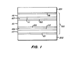
- Figure 1 is a schematic diagram of an assembly consisting of a double coated radiographic element sandwiched between two intensifying screens.
- the double coated radiographic elements of this invention offer the capability of producing superimposed silver images capable of transmission viewing which can satisfy the highest standards of the art in terms of speed and sharpness.
- the radiographic elements are capable of producing a wide range of contrasts merely by altering the choice of intensifying screens employed in combination with the radiographic elements.
- the radiographic element is achieved by constructing the radiographic element with a transparent film support and first and second emulsion layer units coated on opposite sides of the support. This allows transmission viewing of the silver images on opposite sides of the support after exposure and processing.
- means are provided for reducing to less than 10 percent crossover of electromagnetic radiation of wavelengths longer than 300 nm capable of forming a latent image in the silver halide emulsion layer units.
- the crossover reducing means In addition to having the capability of absorbing longer wavelength radiation during imagewise exposure of the emulsion layer units the crossover reducing means must also have the capability of being decolorized in less than 90 seconds during processing, so that no visual hindrance is presented to viewing the superimposed silver images.
- the crossover reducing means decreases crossover to less than 10 percent, preferably reduces crossover to less than 5 percent, and optimally less than 3 percent.
- the crossover percent being referred to also includes "false crossover", apparent crossover that is actually the product of direct X-radiation absorption. That is, even when crossover of longer wavelength radiation is entirely eliminated, measured crossover will still be in the range of 1 to 2 percent, attributable to the X-radiation that is directly absorbed by the emulsion farthest from the intensifying screen.
- Crossover percentages are determined by the procedures set forth in Abbott et al U.S. Patents 4,425,425 and 4,425,426.
- the radiographic elements of this invention differ from conventional double coated radiographic elements in requiring that the first and second emulsion layer units exhibit significantly different speeds.
- the first silver halide emulsion layer unit exhibits a speed at 1.0 above minimum density which is at least twice that of the second silver halide emulsion layer unit. While the best choice of speed differences between the first and second emulsion layer units can differ widely, depending up the contrast of each individual emulsion and the application to be served, in most instances the first emulsion layer unit will exhibit a speed that is from 2 to 10 times that of the second emulsion layer unit.
- the first emulsion layer unit exhibits a speed that is from about 2 to 4 times that of the second emulsion layer unit. So long as the relative speed relationships are satisfied, the first and second emulsion units can cover the full range of useful radiographic imaging speeds.
- sensitometric characterizations of double coated radiographic elements generate characteristic (density vs. log exposure) curves that are the sum of two identical emulsion layer units, one coated on each of the two sides of the transparent support. Therefore, to keep speed and other sensitometric measurements (minimum density, contrast, maximum density, etc.) as compatible with customary practices as possible, the speed and other sensitometric characteristics of the first silver halide emulsion layer unit are determined with the first silver halide emulsion unit replacing the second silver halide emulsion unit to provide an arrangement with the first silver halide emulsion unit present on both sides of the tranparent support.
- the speed and other sensitometric characteristics of the second silver halide emulsion layer unit are similarly determined with the second silver halide emulsion unit replacing the first silver halide emulsion unit to provide an arrangement with the second silver halide emulsion unit present on both sides of the tranparent support. While speed is measured at 1.0 above minimum density, it is recognized that this is an arbitrary selection point, chosen simply because it is typical of art speed measurements. For nontypical characteristic curves (e.g., direct positive imaging or unusual curve shapes) another speed reference point can be selected.
- the remaining features of the double coated radiographic elements of this invention can take any convenient conventional form.
- a radiographic element 100 is positioned between a pair of light emitting intensifying screens 201 and 202.
- the radiographic element support is comprised of a transparent radiographic support element 101, typically blue tinted, capable of transmitting light to which it is exposed and optionally, similarly transmissive subbing layer units 103 and 105.
- a transparent radiographic support element 101 typically blue tinted, capable of transmitting light to which it is exposed and optionally, similarly transmissive subbing layer units 103 and 105.
- On the first and second opposed major faces 107 and 109 of the support formed by the under layer units are crossover reducing hydrophilic colloid layers 111 and 113, respectively.
- each of the emulsion layer units is formed of one or more hydrophilic colloid layers including at least one silver halide emulsion layer.
- hydrophilic colloid protective overcoat layers 119 and 121 are optional hydrophilic colloid protective overcoat layers 119 and 121, respectively. All of the hydrophilic colloid layers are permeable to processing solutions.
- the assembly is imagewise exposed to X radiation.
- the X radiation is principally absorbed by the intensifying screens 201 and 202, which promptly emit light as a direct function of X ray exposure.
- the intensifying screens 201 and 202 which promptly emit light as a direct function of X ray exposure.
- the light recording latent image forming emulsion layer unit 115 is positioned adjacent this screen to receive the light which it emits. Because of the proximity of the screen 201 to the emulsion layer unit 115 only minimal light scattering occurs before latent image forming absorption occurs in this layer unit. Hence light emission from screen 201 forms a sharp image in emulsion layer unit 115.
- crossover reducing layers 111 and 113 are interposed between the screen 201 and the remote emulsion layer unit and are capable of intercepting and attenuating this remaining light. Both of these layers thereby contribute to reducing crossover exposure of emulsion layer unit 117 by the screen 201.
- the screen 202 produces a sharp image in emulsion layer unit 117, and the light absorbing layers 111 and 113 similarly reduce crossover exposure of the emulsion layer unit 115 by the screen 202.
- the radiographic element 100 is removed from association with the intensifying screens 210 and 202 and processed in a rapid access processor-that is, a processor, such as an RP-X-OmatTM processor, which is capable of producing a image bearing radiographic element dry to the touch in less than 90 seconds.
- a rapid access processor that is, a processor, such as an RP-X-OmatTM processor, which is capable of producing a image bearing radiographic element dry to the touch in less than 90 seconds.
- Rapid access processors are illustrated by Barnes et al U.S. Patent 3,545,971 and Akio et al published European Patent Application 248,390.
- radiographic elements satisfying the requirements of the present invention are specifically identified as being those that are capable of emerging dry to the touch when processed in 90 seconds according to the following reference conditions:
- the preferred radiographic elements of the present invention make possible the unique combination of advantages set forth above by employing (1) substantially optimally spectrally sensitized tabular grain emulsions in the emulsion layer units to reach low crossover levels while achieving the high covering power and other known advantages of tabular grain emulsions, (2) one or more particulate dyes in the interlayer units to further reduce crossover to less than 10 percent without emulsion desensitization and minimal or no residual dye stain, and (3) hydrophilic colloid swell and coverage levels compatible with obtaining uniform coatings, rapid access processing, and reduced or eliminated wet pressure sensitivity.
- particulate dye optical densities of 1.00 are effective to reduce crossover to less than 10 percent
- particulate dye densities can be increased until radiographic element crossover is effectively eliminated. For example, by increasing the particulate dye concentration so that it imparts a density of 2.0 to the radiographic element, crossover is reduced to only 1 percent.
- the size of the dye particles is chosen to facilitate coating and rapid decolorization of the dye. In general smaller dye particles lend themselves to more uniform coatings and more rapid decolorization.
- the dye particles employed in all instances have a mean diameter of less than 10.0 ⁇ m and preferably less than 1.0 u.m. There is no theoretical limit on the minimum sizes the dye particles can take.
- the dye particles can be most conveniently formed by crystallization from solution in sizes ranging down to about 0.01 nm or less. Where the dyes are initially crystallized in the form of particles larger than desired for use, conventional techniques for achieving smaller particle sizes can be employed, such as ball milling, roller milling, sand milling, and the like.
- hydrophilic colloid layers are most commonly gelatin and gelatin derivatives (e.g., acetylated or phthalated gelatin).
- the hydrophilic colloid must be coated at a layer coverage of at least 10 mg/dm 2 , Any convenient higher coating coverage can be employed, provided the total hydrophilic colloid coverage per side of the radiographic element does not exceed that compatible with rapid access processing.
- Hydrophilic colloids are typically coated as aqueous solutions in the pH range of from about 5 to 6, most typically from 5.5 to 6.0, to form radiographic element layers.
- the dyes which are selected for use in the practice of this invention are those which are capable of remaining in particulate form at those pH levels in aqueous solutions.
- Dyes which by reason of their chromophoric make up are inherently ionic, such as cyanine dyes, as well as dyes which contain substituents which are ionically dissociated in the above-noted pH ranges of coating may in individual instances be sufficiently insoluble to satisfy the requirements of this invention, but do not in general constitute preferred classes of dyes for use in the practice of the invention.
- dyes with sulfonic acid substituents are normally too soluble to satisfy the requirements of the invention.
- nonionic dyes with carboxylic acid groups (depending in some instances on the specific substitution location of the carboxylic acid group) are in general insoluble under aqueous acid coating conditions. Specific dye selections can be made from known dye characteristics or by observing solubilities in the pH range of from 5.5 to 16.0 at normal layer coating temperatures-e.g., at a reference temperature of 40 C.
- Preferred particulate dyes are nonionic polymethine dyes, which include the merocyanine, oxonol, hemioxonol, styryl, and arylidene dyes.
- the merocyanine dyes include, joined by a methine linkage, at least one basic heterocyclic nucleus and at least one acidic nucleus.
- the nuclei can be joined by an even number or methine groups or in so- called "zero methine" merocyanine dyes, the methine linkage takes the form of a double bond between methine groups incorporated in the nuclei.
- Basic nuclei such as azolium or azinium nuclei, for example, include those derived from pyridinium, quinolinium, isoquinolinium, oxazolium, pyrazolium, pyrrolium, indolium, oxadiazolium, 3H- or 1 H-benzoindolium, pyrrolopyridinium, phenanthrothiazolium, and acenaph- thothiazolium quaternary salts.
- Exemplary of the basic heterocyclic nuclei are those satisfying Formulae I and II. where
- Merocyanine dyes link one of the basic heterocyclic nuclei described above to an acidic keto methylene nucleus through a methine linkage as described above.
- Exemplary acidic nuclei are those which satisfy Formula III.
- Useful hemioxonol dyes exhibit a keto methylene nucleus as shown in Formula III and a nucleus as shown in Formula IV.
- G 3 and G 4 may be the same or different and may represent alkyl, substituted alkyl, aryl, substituted aryl, or aralkyl, as illustrated for R ring substituents in Formula I or G 3 and G 4- taken together complete a ring system derived from a cyclic secondary amine, such as pyrrolidine, 3-pyrroline, piperidine, piperazine (e.g., 4-methylpiperazine and 4-phenylpiperazine), morpholine, 1,2,3,4-tetrahydroquinoline, decahydroquinoline, 3-azabicyclo[3,2,2]nonane, indoline, azetidine, and hexahydroazepine.
- a cyclic secondary amine such as pyrrolidine, 3-pyrroline, piperidine, piperazine (e.
- Exemplary oxonol dyes exhibit two keto methylene nuclei as shown in Formula III joined through one or higher uneven number of methine groups.
- Useful arylidene dyes exhibit a keto methylene nucleus as shown in Formula III and a nucleus as shown in Formula V joined by a methine linkage as described above containing one or a higher uneven number of methine groups.
- G 3 and G 4 are as previously defined.
- a specifically preferred class of oxonol dyes for use in the practice of the invention are the oxonol dyes disclosed in Factor and Diehl European published patent application 299,435. These oxonol dyes satisfy Formula VI. wherein R 1 and R 2 each independently represent alkyl of from 1 to 5 carbon atoms.
- arylidene dyes for use in the practice of the invention are the arylidene dyes disclosed in Diehl and Factor European published patent applications 274,723 and 294,461. These arylidene dyes satisfy Formula VII. wherein
- Oxazole and oxazoline pyrazolone merocyanine particulate dyes are also contemplated.
- the particulate dyes of Formula VIII are representative.
- R 1 and R 2 are each independently substituted or unsubstituted alkyl or substituted or unsubstituted aryl, or together represent the atoms necessary to complete a substituted or unsubstituted 5-or 6-membered ring.
- R 3 and R 4 each independently represents H, substituted or unsubstituted alkyl, substituted or unsubstituted aryl, C0 2 H, or NHS0 2 R s .
- R 5 is H, substituted or unsubstituted alkyl, substituted or unsubstituted aryl, carboxylate (i.e., COOR where R is substituted or unsubstituted alkyl), or substituted or unsubstituted acyl, R 6 and R 7 are each independently substituted or unsubstituted alkyl or substituted or unsubstituted aryl, and n is 1 or 2.
- R 8 is either substituted or unsubstituted alkyl, or is part of a double bond between the ring carbon atoms to which R 1 and R 2 are attached. At least one of the aryl rings of the dye molecule must have at least one substituent that is C0 2 H or NHS0 2 R 6 .
- Oxazole and oxazoline benzoylacetonitrile merocyanine particulate dyes are also contemplated.
- the particulate dyes of Formula IX are representative.
- R 1 , R 2 , R 3 , R 4 , R s , and R 6 may each be substituted or unsubstituted alkyl or substituted or unsubstituted aryl, preferably substituted or unsubstituted alkyl of 1 to 6 carbon atoms or substituted or unsubstituted aryl of 6 to 12 carbon atoms.
- R 7 may be substituted or unsubstituted alkyl of from 1 to 6 carbon atoms.
- the alkyl or aryl groups may be substituted with any of a number of substituents as is known in the.
- substituents include halogen, alkoxy, ester groups, amido, acyl, and alkylamino.
- alkyl groups include methyl, ethyl, n-propyl, isopropyl, n-butyl, isobutyl, n-pentyl, n-hexyl, or isohexyl.
- aryl groups include phenyl, naphthyl, anthracenyl, pyridyl, and styryl.
- R 1 and R 2 may also together represent the atoms necessary to complete a substituted or unsubstituted 5- or 6-membered ring, such as phenyl, naphthyl, pyridyl, cyclohexyl, dihydronaphthyl, or acenaphthyl.
- This ring may be substituted with substituents, other than those, such as sulfo substituents, that would tend to increase the solubility of the dye so much as to cause it to become soluble at coating pH's.
- substituents include halogen, alkyl, alkoxy, ester, amido, acyl, and alkylamino.
- Useful bleachable particulate dyes can be found among a wide range of cyanine, merocyanine, oxonol, arylidene (i.e., merostyryl), anthraquinone, triphenylmethine, azo, azomethine, and other dyes. Such dyes are illustrated by those which satisfy the criteria of Formula X.
- D is a chromophoric light-absorbing compound, which may or may not comprise an aromatic ring if y is not 0 and which comprises an aromatic ring if y is 0,
- A is an aromatic ring bonded directly or indirectly to D
- X is a substituent, either on A or on an aromatic ring portion of D, with an ionizable proton
- y is 0 to 4
- n is 1 to 7, where the dye is substantially aqueous insoluble at a pH of 6 or below and substantially aqueous soluble at a pH of 8 or above.
- Synthesis of the particulate dyes can be achieved by procedures known in the art for the synthesis of dyes of the same classes. For example, those familiar with techniques for dye synthesis disclosed in "The Cyanine Dyes and Related Compounds", Frances Hamer, Interscience Publishers, 1964, could readily synthesize the cyanine, merocyanine, merostyryl, and other polymethine dyes.
- the oxonol, anthraquinone, triphenylmethane, azo, and azomethine dyes are either known dyes or substituent variants of known dyes of these classes and can be synthesized by known or obvious variants of known synthetic techniques forming dyes of these classes.
- particulate bleachable dyes useful in the practice of this invention include the following:
- the dye can be added directly to the hydrophilic colloid as a particulate solid or can be converted to a particulate solid after it is added to the hydrophilic colloid.
- One example of the latter technique is to dissolve a dye which is not water soluble in a solvent which is water soluble.
- the dye solution is mixed with an aqueous hydrophilic colloid, followed by noodling and washing of the hydrophilic colloid (see Research Disclosure, Item 17643, cited above, Section II), the dye solvent is removed, leaving particulate dye dispersed within the hydrophilic colloid.
- any water insoluble dye which that is soluble in a water miscible organic solvent can be employed as a particulate dye in the practice of the invention, provided the dye is susceptible to bleaching under processing conditions-e.g., at alkaline pH levels.
- contemplated water miscible organic solvents are methanol, ethyl acetate, cyclohexanone, methyl ethyl ketone, 2-(2-butoxyethoxy)ethyl acetate, triethyl phosphate, methylacetate, acetone, ethanol, and dimethylformamide.
- Dyes preferred for use with these solvents are sulfonamide substituted arylidene dyes, specifically preferred examples of which are set forth about in Tables IIA and III.
- the dyes employed in the under layer units must be substantially decolorized on processing.
- substantially decolorized is employed to mean that the dye in the under layer units raises the minimum density of the radiographic element when fully processed under the reference processing conditions, stated above, by no more than 0.1, preferably no more than 0.05, within the visible spectrum. As shown in the examples below the preferred particulate dyes produce no significant increase in the optical density of fully processed radiographic elements of the invention.
- UV absorber preferably blended with the dye in each of crossover reducing layers 111 and 113.
- Any conventional UV absorber can be employed for this purpose.
- Illustrative useful UV absorbers are those disclosed in Research Disclosure, Item 18431, cited above, Section V, or Research Disclosure, Item 17643, cited above, Section VIII(C).
- Preferred UV absorbers are those which either exhibit minimal absorption in the visible portion of the spectrum or are decolorized on processing similarly as the crossover reducing dyes.
- At least one additional hydrophilic colloid layer specifically at one halide emulsion layer unit comprised of a spectrally sensitized silver bromide or bromoiodide tabular grain emulsion layer.
- At least 50 percent (preferably at least 70 percent and optimally at least 90 percent) of the total grain projected area of the tabular grain emulsion is accounted for by tabular grains having a thickness less than 0.3 u.m (preferably less than 0.2 j.Lm) and an average aspect ratio of greater than 5:1 (preferably greater than 8:1 and optimally at least 12:1).
- Preferred tabular grain silver bromide and bromoiodide emulsions are those disclosed by Wilgus et al U.S. Patent 4,434,226; Kofron et al U.S. Patent 4,439,530; Abbott et al U.S. Patents 4,425,425 and 4,425,426; Dickerson U.S. Patent 4,414,304; Maskasky U.S. Patent 4,425,501; and Dickerson U.S. Patent 4,520,098.
- the tabular grain emulsions are substantially optimally spectrally sensitized. That is, sufficient spectral sensitizing dye is adsorbed to the emulsion grain surfaces to achieve at least 60 percent of the maximum speed attainable from the emulsions under the contemplated conditions of exposure. It is known that optimum spectral sensitization is achieved at about 25 to 100 percent or more of monolayer coverage of the total available surface area presented by the grains.
- the preferred dyes for spectral sensitization are polymethine dyes, such as cyanine, merocyanine, hemicyanine, hemioxonol, and merostyryl dyes. Specific examples of spectral sensitizing dyes and their use to sensitize tabular grain emulsions are provided by Kofron et al U.S. Patent 4,439,520.
- the tabular grain emulsions are rarely put to practical use without chemical sensitization. Any convenient chemical sensitization of the tabular grain emulsions can be undertaken.
- the tabular grain emulsions are preferably substantially optimally (as defined above) chemically and spectrally sensitized.
- Useful chemical sensitizations including noble metal (e.g., gold) and chalcogen (e.g., sulfur and/or selenium) sensitizations as well as selected site epitaxial sensitizations, are disclosed by the patents cited above relating to tabular grain emulsions, particularly Kofron et al and Maskasky.
- the emulsion layers can include as vehicles any one or combination of various conventional hardenable hydrophilic colloids alone or in combination with vehicle extenders, such as latices and the like.
- vehicle extenders such as latices and the like.
- the vehicles and vehicle extenders of the emulsion layer units can be identical to those of the interlayer units.
- the vehicles and vehicle extenders can be selected from among those disclosed by Research Disclosure, Item 17643, cited above, Section IX.
- Specifically preferred hydrophilic colloids are gelatin and gelatin derivatives.
- each emulsion layer unit should contain a silver coverage from about 18 to 30 mg/dm 2 , preferably 21 to 27 mg/dm 2 .
- overcoat layers can be formed of the same vehicles and vehicle extenders disclosed above in connection with the emulsion layers.
- the overcoat layers are most commonly gelatin or a gelatin derivative.
- the total hydrophilic colloid coverage on each major surface of the support must be at least 35 mg/dm 2 . It is an observation of this invention that it is the total hydrophilic colloid coverage on each surface of the support and not, as has been generally believed, simply the hydrophilic colloid coverage in each silver halide emulsion layer that controls its wet pressure sensitivity.
- the emulsion layer can contain as little as 20 mg/dm 2 of hydrophilic colloid.
- the total hydrophilic coating coverage on each major surface of the support must be less than 65 mg/dm 2 , preferably less than 55 mg/dm 2 , and the hydrophilic colloid layers must be substantially fully forehardened.
- substantially fully forehardened it is meant that the processing solution permeable hydrophilic colloid layers are forehardened in an amount sufficient to reduce swelling of these layers to less than 300 percent, percent swelling being determined by the following reference swell determination procedure: (a) incubating said radiographic element at 38° C for 3 days at 50 percent relative humidity, (b) measuring layer thickness, (c) immersing said radiographic element in distilled water at 21 ° C for 3 minutes, and (d) determining the percent change in layer thickness as compared to the layer thickness measured in step (b).
- This reference procedure for measuring forehardening is disclosed by Dickerson U.S. Patent 4,414,304. Employing this reference procedure, it is preferred that the hydrophilic colloid layers be sufficiently forehardened that swelling is reduced to less than 200 percent under the stated test conditions.
- Transparent film supports such as any of those disclosed in Research Disclosure, Item 17643, cited above, Section XIV, are all contemplated. Due to their superior dimensional stability the transparent film supports preferred are polyester supports. Poly(ethylene terephthalate) is a specifically preferred polyester film support. The support is typically tinted blue to aid in the examination of image patterns. Blue anthracene dyes are typically employed for this purpose. In addition to the film itself, the support is usually formed with a subbing layer on the major surface intended to receive the under layer units. For further details of support construction, including exemplary incorporated anthracene dyes and subbing layers, refer to Research Disclosure, Item 18431, cited above, Section XII.
- the radiographic elements can and in most practical applications will contain additional conventional features.
- the emulsion layer units can contain stabilizers, antifoggants, and antikinking agents of the type set forth in Section II, and the overcoat layers can contain any of variety of conventional addenda of the type set forth in Section IV.
- the outermost layers of the radiographic element can also contain matting agents of the type set out in Research Disclosure, Item 17643, cited above, Section XV1. Referring further to Research Disclosure, Item 17643, incorporation of the coating aids of Section XI, the plasticizers and lubricants of Section XII, and the antistatic layers of Section XIII, are each contemplated.
- This screen has a composition and structure corresponding to that of a commercial, general purpose screen. It consists of a terbium activated gadolinium oxysulfide phosphor having a median particle size of 7 u.m coated on a white pigmented polyester support in a PermuthaneTM polyurethane binder at a total phosphor coverage of 7.0 g/dm 2 at a phosphor to binder ratio of 15:1.
- This screen has a composition and structure corresponding to that of a commercial, medium resolution screen. It consists of a terbium activated gadolinium oxysulfide phosphor having a median particle size of 7 /.l.m coated on a white pigmented polyester support in a PermuthaneTM polyurethane binder at a total phosphor coverage of 5.9 g/dm 2 at a phosphor to binder ratio of 15:1 and containing 0.017535% by weight of a 100:1 weight ratio of a yellow dye and carbon.
- This screen has a composition and structure corresponding to that of a commercial, high resolution screen. It consists of a terbium activated gadolinium oxysulf ide phosphor having a median particle size of 5 ⁇ m coated on a blue tinted clear polyester support in a PermuthaneTM polyurethane binder at a total phosphor coverage of 3.8 g/dm 2 at a phosphor to binder ratio of 21:1 and containing 0.0015% carbon.
- Radiographic element A was a double coated radiographic element exhibiting near zero crossover.
- Radiographic element A was constructed of a blue-tinted polyester support. On each side the support a crossover reducing layer consisting of gelatin (1.6g/m z ) containing 320 mg/m 2 of a 1:1 weight ratio mixture of Dyes 56 and 59.
- Fast (F) and slow (S) emulsion layers were coated on opposite sides of the support over the crossover reducing layers. Both emulsions were green-sensitized high aspect ratio tabular grain silver bromide emulsions, where the term "high aspect ratio" is employed as defined by Abbott et al U.S. Patent 4,425,425 to require that at least 50 percent of the total grain projected area be accounted for by tabular grains having a thickness of less than 0.3 ⁇ m and having an average aspect ratio of greater than 8:1.
- the first emulsion exhibited an average grain diameter of 3.0 ⁇ m and an average grain thickness of 0.13 u.m.
- the second emulsion exhibited an average grain diameter of 1.2 u.m and an average grain thickness of 0.13 u.m.
- Each emulsion was spectrally sensitized with 400 mg/Ag mol of anhydro-5,5-dichloro-9-ethyl-3,3'-bis (3-sulfopropyl)- oxacarbocyanine hydroxide, followed by 300 mg/Ag mol of potassium iodide.
- the emulsion layers were each coated with a silver coverage of 2.42 g/m 2 and a gelatin coverage of 2.85 g/m 2 .
- Protective gelatin layers (0.69 g/m 2 ) were coated over the emulsion layers.
- Each of the gelatin containing layers were hardened with bis(vinylsulfonylmethyl) ether at 1% of the total gelatin.
- Emulsion F When coated as described above, but symmetrically, with Emulsion F coated on both sides of the support and Emulsion S omitted, using a Screen X pair, Emulsion F exhibited a relative log speed of 144. Similarly, Emulsion S when coated symmetrically with Emulsion F omitted exhibited a relative log speed of 68.
- the emulsions thus differed in speed by a relative log speed of 76 (or 0.76 log E, where E represents exposure in meter-candle-seconds).
- a relative log speed difference of 30 renders one emulsion twice as fast as the other. All speeds in the examples are referenced to 1.0 above Dmin.
- Radiographic element B was a conventional double coated radiographic element exhibiting extended exposure latitude.
- Radiographic element B was constructed of a blue-tinted polyester support. Identical emulsion layers (L) were coated on opposite sides of the support. The emulsion employed was a green-sensitized polydispersed silver bromoiodide emulsion. The same spectral sensitizing dye was employed as in Element A, but only 42 mg/Ag mole was required, since the emulsion was not a high aspect ratio tabular grain emulsion and therefore required much less dye for substantially optimum sensitization. Each emulsion layer was coated to provide a silver coverage of 2.62 g/m 2 and a gelatin coverage of 2.85 g/m 2. Protective gelatin layers (0.70 g/m 2 ) were coated over the emulsion layers. Each of the layers were hardened with bis-(vinylsulfonylmethyl) ether at 0.5% of the total gelatin.
- the film When coated as described above, using a Screen X pair, the film exhibited a relative log E speed of 80 and a contrast of 1.6.
- Optical densities are expressed in terms of diffuse density as measured by an X-rite mOdel 310TM densitometer, which was calibrated to ANSI standard PH 2.19 and was traceable to a National Bureau of Standards calibration step tablet.
- the characteristic curve (density vs. log E) was plotted for each radiographic element processed.
- the average gradient presented in Table XII below under the heading Contrast, was determined from the characteristic curve at densities of 0.25 and 2.0 above minimum density.
- assemblies I and II are in fact the same assembly, which was simply reversed in its orientation during exposure.
- assemblies IV and V are the same assembly simply reversed in orientation during exposure.
- the radiographic film, Element A satisfying the requirements of the invention by exhibiting a crossover of less than 10% and a greater than 2X difference in emulsion speeds showed a contrast in Assembly I 0.4 greater than in Assembly II.
- the control radiographic element B which exhibited a higher crossover and identical emulsion layer units on opposite sides of the support, showed no variation in contrast between Assemblies IV and V.
- radiographic element A When an entirely different pair of screens, a Screen Y pair, were substituted for the X and Z screen pair, radiographic element A exhibited still a third average contrast, while control radiographic element B still exhibited the same average contrast.
- double coated radiographic elements exhibiting crossover levels of less than 10 percent and a first emulsion layer unit on one side of a transparent film support that exhibits a contrast of less than 2.0 (based on density measurements at 0.25 and 2.0 above minimum density with the emulsion layer unit coated on both sides of a transparent support) and a second emulsion layer unit on the other side the transparent film support that exhibits a contrast of at least 2.5 (similarly determined) offers the capability of obtaining useful information over an extended exposure lattitude, such that required to obtain useful chest cavity information in both lung and heart areas of a radiographic image.
- the first and second emulsion layer units differ in average density from 1.0 to 1.5.
- Radiographic element C was a double coated radiographic element exhibiting near zero crossover.
- Radiographic element C was constructed of a low crossover support composite (LXO) identical to that of element A, described above.
- LXO low crossover support composite
- FLC Fast low contrast
- SHC slow high contrast
- Emulsion FLC When coated symmetrically, with Emulsion FLC coated on both sides of the support and Emulsion SHC omitted, using a Screen X pair, Emulsion FLC exhibited a relative log speed of 113 and an average contrast of 1.98. Similarly, Emulsion SHC when coated symmetrically with Emulsion FLC omitted exhibited a relative log speed of 69 and an average contrast of 2.61. The emulsions thus differed in average contrast by 0.63 while differing in speed by 44 relative log speed units (or 0.44 log E).
- the foregoing comparisons provide a striking demonstration of the advantages which a radiologist can realize from the the present invention.
- the present invention offers the radiologist a variety of image contrasts using only a single type of radiographic element.
Landscapes
- Physics & Mathematics (AREA)
- General Physics & Mathematics (AREA)
- Silver Salt Photography Or Processing Solution Therefor (AREA)
- Conversion Of X-Rays Into Visible Images (AREA)
Applications Claiming Priority (4)
| Application Number | Priority Date | Filing Date | Title |
|---|---|---|---|
| US31434189A | 1989-02-23 | 1989-02-23 | |
| US314341 | 1989-02-23 | ||
| US385114 | 1989-07-26 | ||
| US07/385,114 US4997750A (en) | 1989-02-23 | 1989-07-26 | Radiographic elements with selected speed relationships |
Publications (3)
| Publication Number | Publication Date |
|---|---|
| EP0384633A2 true EP0384633A2 (fr) | 1990-08-29 |
| EP0384633A3 EP0384633A3 (en) | 1990-10-31 |
| EP0384633B1 EP0384633B1 (fr) | 1996-04-24 |
Family
ID=26979320
Family Applications (1)
| Application Number | Title | Priority Date | Filing Date |
|---|---|---|---|
| EP90301549A Expired - Lifetime EP0384633B1 (fr) | 1989-02-23 | 1990-02-14 | Eléments radiographiques avec des rapports de sensibilité sélectionnés |
Country Status (8)
| Country | Link |
|---|---|
| US (1) | US4997750A (fr) |
| EP (1) | EP0384633B1 (fr) |
| JP (1) | JP2927490B2 (fr) |
| KR (1) | KR900013346A (fr) |
| AU (1) | AU624677B2 (fr) |
| BR (1) | BR9000889A (fr) |
| CA (1) | CA2008301A1 (fr) |
| DE (1) | DE69026636T2 (fr) |
Cited By (11)
| Publication number | Priority date | Publication date | Assignee | Title |
|---|---|---|---|---|
| EP0440367A1 (fr) * | 1990-01-23 | 1991-08-07 | Konica Corporation | Matériau photographique À l'halogénure d'argent sensible à la lumière ayant une haute sensibilité et une grande finesse |
| EP0449101A1 (fr) * | 1990-03-29 | 1991-10-02 | Eastman Kodak Company | Eléments, assemblages et emballages radiographiques asymétriques |
| EP0470733A1 (fr) * | 1990-08-08 | 1992-02-12 | Konica Corporation | Matériau photographique à l'halogénure d'argent sensible à la lumière |
| EP0501423A1 (fr) * | 1991-02-27 | 1992-09-02 | Konica Corporation | Matériau radiographique |
| EP0520409A1 (fr) * | 1991-06-26 | 1992-12-30 | Konica Corporation | Matériau photographique à l'halogénure d'argent sensible à la lumière adapté aux besoins photographiques de qualité d'image et gradation, et procédé de formation d'image par celui-ci |
| WO1993011458A1 (fr) * | 1991-11-27 | 1993-06-10 | E.I. Du Pont De Nemours And Company | Colorants de sensibilisation a l'arylidene pour grains tabulaires |
| EP0524650A3 (en) * | 1991-07-25 | 1993-06-30 | Konica Corporation | Variable contrast x-ray material |
| WO1995021402A1 (fr) * | 1994-02-04 | 1995-08-10 | Eastman Kodak Company | Systeme radiographique destine a l'imagerie orthopedique |
| EP1246005A1 (fr) * | 2001-03-29 | 2002-10-02 | Agfa-Gevaert | Matériau photographique à l'halogénure d'argent pour la mammographie |
| EP1130461A3 (fr) * | 2000-02-28 | 2002-11-27 | Eastman Kodak Company | Film radiographique visuellement adaptable à haut contrast et assemblage pour l'enregistrement et la formation d'images |
| US6573019B1 (en) | 2001-03-29 | 2003-06-03 | Agfa-Gevaert | Photographic silver halide photographic material for mammography |
Families Citing this family (32)
| Publication number | Priority date | Publication date | Assignee | Title |
|---|---|---|---|---|
| DE69029676T2 (de) * | 1989-04-06 | 1997-05-07 | Fuji Photo Film Co Ltd | Photographisches Silberhalogenidmaterial und Verarbeitungsmethode dafür |
| IT1230335B (it) * | 1989-07-12 | 1991-10-18 | Minnesota Mining & Mfg | Cassetta con schermi di rinforzo per uso con un film radiografico. |
| US5455139A (en) * | 1990-01-23 | 1995-10-03 | Konica Corporation | Light-sensitive silver halide photographic material having high sensitivity and high sharpness |
| JP2847428B2 (ja) * | 1990-10-12 | 1999-01-20 | コニカ株式会社 | X線用ハロゲン化銀写真感光材料 |
| US5399470A (en) * | 1991-08-16 | 1995-03-21 | Eastman Kodak Company | Minimal crossover radiographic elements and assemblies adapted for flesh and bone imaging |
| US5252443A (en) * | 1992-02-03 | 1993-10-12 | Eastman Kodak Company | Means for assuring proper orientation of the film in an asymmetrical radiographic assembly |
| IT1255402B (it) * | 1992-07-02 | 1995-10-31 | Struttura radiografica con ridotto cross-over a guisa di immagine e trattabilita' rapidissima | |
| IT1256597B (it) * | 1992-10-05 | 1995-12-12 | Assemblaggio di film e schermi radiografici a contrasto multiplo | |
| US5259016A (en) * | 1992-10-22 | 1993-11-02 | Eastman Kodak Company | Assembly for radiographic imaging |
| JPH0829923A (ja) | 1994-07-11 | 1996-02-02 | Konica Corp | ハロゲン化銀写真感光材料と放射線蛍光増感紙との組体 |
| US5491058A (en) | 1994-08-09 | 1996-02-13 | Eastman Kodak Company | Film for duplicating silver images in radiographic films |
| US5886353A (en) * | 1995-04-21 | 1999-03-23 | Thermotrex Corporation | Imaging device |
| US5830629A (en) * | 1995-11-01 | 1998-11-03 | Eastman Kodak Company | Autoradiography assemblage using transparent screen |
| US5871892A (en) * | 1996-02-12 | 1999-02-16 | Eastman Kodak Company | Portal radiographic imaging |
| US5952163A (en) * | 1998-01-14 | 1999-09-14 | Eastman Kodak Company | Direct dental X-ray films adapted for room light handling |
| US6200723B1 (en) | 2000-02-28 | 2001-03-13 | Eastman Kodak Company | Rapidly processable and directly viewable radiographic film with visually adaptive contrast |
| US6190844B1 (en) | 2000-02-28 | 2001-02-20 | Eastman Kodak Company | Method of providing digital image in radiographic film having visually adaptive contrast |
| US6358661B1 (en) | 2000-11-06 | 2002-03-19 | Eastman Kodak Company | Visually adaptive radiographic film and imaging assembly |
| US6391531B1 (en) | 2000-11-06 | 2002-05-21 | Eastman Kodak Company | Low silver radiographic film and imaging assembly for thoracic imaging |
| US6361918B1 (en) | 2000-11-06 | 2002-03-26 | Eastman Kodak Company | High speed radiographic film and imaging assembly |
| US6350554B1 (en) | 2000-11-06 | 2002-02-26 | Eastman Kodak Company | High contrast visually adaptive radiographic film and imaging assembly for orthopedic imaging |
| US6387586B1 (en) | 2000-11-06 | 2002-05-14 | Eastman Kodak Company | High contrast visually adaptive radiographic film and imaging assembly for thoracic imaging |
| US6485882B1 (en) | 2001-06-28 | 2002-11-26 | Eastman Kodak Company | Asymmetric contrast portal imaging assembly and method of use |
| US6485881B1 (en) | 2001-06-28 | 2002-11-26 | Eastman Kodak Company | Asymmetric speed portal imaging assembly and method of use |
| US6485879B1 (en) * | 2001-06-28 | 2002-11-26 | Eastman Kodak Company | Portal imaging assembly with asymmetric films and asymmetric screens and method of use |
| US6489077B1 (en) | 2001-06-28 | 2002-12-03 | Eastman Kodak Company | Portal imaging assembly with pair of asymmetric screens and method of use |
| US6680154B1 (en) | 2002-07-23 | 2004-01-20 | Eastman Kodak Company | Asymmetric radiographic film for mammography and method of processing |
| US7015479B2 (en) * | 2003-07-31 | 2006-03-21 | Eastman Kodak Company | Digital film grain |
| EP2411872A1 (fr) | 2009-03-27 | 2012-02-01 | Carestream Health, Inc. | Films d'halogénure d'argent radiographiques présentant un révélateur incorporé |
| EP2259136A1 (fr) | 2009-06-03 | 2010-12-08 | Carestream Health, Inc. | Pellicule avec colorant bleu |
| US8617801B2 (en) * | 2009-06-03 | 2013-12-31 | Carestream Health, Inc. | Film with blue dye |
| US9324469B1 (en) * | 2014-10-31 | 2016-04-26 | Geraldine M. Hamilton | X-ray intensifying screens including micro-prism reflective layer for exposing X-ray film, X-ray film cassettes, and X-ray film assemblies |
Family Cites Families (11)
| Publication number | Priority date | Publication date | Assignee | Title |
|---|---|---|---|---|
| DE1000687B (de) * | 1957-01-10 | 1957-01-10 | Agfa Ag | Verfahren zur Herstellung von Roentgenaufnahmen |
| FR86640E (fr) * | 1964-10-23 | 1966-03-11 | Kodak Pathe | Nouveau produit radiographique |
| IL56324A0 (en) * | 1978-12-28 | 1979-03-12 | Hoffman A | Method and apparatus for producing a high speed high resolution radiation sensitive article and a high speed high resolution radiation sensitive article |
| US4707435A (en) * | 1981-05-26 | 1987-11-17 | Minnesota Mining And Manufacturing Company | Industrial X-ray system |
| US4425425A (en) * | 1981-11-12 | 1984-01-10 | Eastman Kodak Company | Radiographic elements exhibiting reduced crossover |
| US4425426A (en) * | 1982-09-30 | 1984-01-10 | Eastman Kodak Company | Radiographic elements exhibiting reduced crossover |
| US4710637A (en) * | 1986-02-10 | 1987-12-01 | Eastman Kodak Company | High efficiency fluorescent screen pair for use in low energy X radiation imaging |
| CA1299424C (fr) * | 1986-12-23 | 1992-04-28 | Donald R. Diehl | Element radiographique a surimpression reduite |
| US4803150A (en) * | 1986-12-23 | 1989-02-07 | Eastman Kodak Company | Radiographic element exhibiting reduced crossover |
| DE3773648D1 (de) * | 1987-01-27 | 1991-11-14 | Agfa Gevaert Nv | Verfahren zur erzeugung von radiographischen mehrfachbildern. |
| IT1226917B (it) * | 1988-07-14 | 1991-02-22 | Minnesota Mining & Mfg | Combinazione di elementi fotosensibili da usare in radiografia. |
-
1989
- 1989-07-26 US US07/385,114 patent/US4997750A/en not_active Expired - Lifetime
-
1990
- 1990-01-23 CA CA002008301A patent/CA2008301A1/fr not_active Abandoned
- 1990-02-09 AU AU49326/90A patent/AU624677B2/en not_active Expired - Fee Related
- 1990-02-14 DE DE69026636T patent/DE69026636T2/de not_active Expired - Fee Related
- 1990-02-14 EP EP90301549A patent/EP0384633B1/fr not_active Expired - Lifetime
- 1990-02-22 BR BR909000889A patent/BR9000889A/pt not_active IP Right Cessation
- 1990-02-23 JP JP2041410A patent/JP2927490B2/ja not_active Expired - Fee Related
- 1990-02-23 KR KR1019900002336A patent/KR900013346A/ko not_active Withdrawn
Cited By (15)
| Publication number | Priority date | Publication date | Assignee | Title |
|---|---|---|---|---|
| EP0440367A1 (fr) * | 1990-01-23 | 1991-08-07 | Konica Corporation | Matériau photographique À l'halogénure d'argent sensible à la lumière ayant une haute sensibilité et une grande finesse |
| EP0449101A1 (fr) * | 1990-03-29 | 1991-10-02 | Eastman Kodak Company | Eléments, assemblages et emballages radiographiques asymétriques |
| EP0470733A1 (fr) * | 1990-08-08 | 1992-02-12 | Konica Corporation | Matériau photographique à l'halogénure d'argent sensible à la lumière |
| US5238795A (en) * | 1990-08-08 | 1993-08-24 | Konica Corporation | Light-sensitive silver halide photographic material |
| EP0501423A1 (fr) * | 1991-02-27 | 1992-09-02 | Konica Corporation | Matériau radiographique |
| US5523198A (en) * | 1991-02-27 | 1996-06-04 | Konica Corporation | Light-sensitive silver halide photographic material |
| US5268251A (en) * | 1991-06-26 | 1993-12-07 | Konica Corporation | Light-sensitive silver halide photographic material image quality- and gradation-adaptable to photographing purposes and image forming method therefor |
| EP0520409A1 (fr) * | 1991-06-26 | 1992-12-30 | Konica Corporation | Matériau photographique à l'halogénure d'argent sensible à la lumière adapté aux besoins photographiques de qualité d'image et gradation, et procédé de formation d'image par celui-ci |
| EP0524650A3 (en) * | 1991-07-25 | 1993-06-30 | Konica Corporation | Variable contrast x-ray material |
| US5275928A (en) * | 1991-11-27 | 1994-01-04 | E. I. Du Pont De Nemours And Company | Arylidene sensitizing dyes for tabular grains |
| WO1993011458A1 (fr) * | 1991-11-27 | 1993-06-10 | E.I. Du Pont De Nemours And Company | Colorants de sensibilisation a l'arylidene pour grains tabulaires |
| WO1995021402A1 (fr) * | 1994-02-04 | 1995-08-10 | Eastman Kodak Company | Systeme radiographique destine a l'imagerie orthopedique |
| EP1130461A3 (fr) * | 2000-02-28 | 2002-11-27 | Eastman Kodak Company | Film radiographique visuellement adaptable à haut contrast et assemblage pour l'enregistrement et la formation d'images |
| EP1246005A1 (fr) * | 2001-03-29 | 2002-10-02 | Agfa-Gevaert | Matériau photographique à l'halogénure d'argent pour la mammographie |
| US6573019B1 (en) | 2001-03-29 | 2003-06-03 | Agfa-Gevaert | Photographic silver halide photographic material for mammography |
Also Published As
| Publication number | Publication date |
|---|---|
| JPH02266344A (ja) | 1990-10-31 |
| AU624677B2 (en) | 1992-06-18 |
| US4997750A (en) | 1991-03-05 |
| CA2008301A1 (fr) | 1990-08-23 |
| KR900013346A (ko) | 1990-09-05 |
| DE69026636T2 (de) | 1997-01-09 |
| AU4932690A (en) | 1990-08-30 |
| BR9000889A (pt) | 1991-02-13 |
| JP2927490B2 (ja) | 1999-07-28 |
| EP0384633B1 (fr) | 1996-04-24 |
| DE69026636D1 (de) | 1996-05-30 |
| EP0384633A3 (en) | 1990-10-31 |
Similar Documents
| Publication | Publication Date | Title |
|---|---|---|
| EP0384633B1 (fr) | Eléments radiographiques avec des rapports de sensibilité sélectionnés | |
| US4994355A (en) | Radiographic elements with selected contrast relationships | |
| US5021327A (en) | Radiographic screen/film assemblies with improved detection quantum efficiencies | |
| US4900652A (en) | Radiographic element | |
| US4803150A (en) | Radiographic element exhibiting reduced crossover | |
| US5108881A (en) | Minimal crossover radiographic elements adapted for varied intensifying screen exposures | |
| EP0276566B1 (fr) | Elément radiographique à effet interimage réduit | |
| US5576156A (en) | Low crossover radiographic elements capable of being rapidly processed | |
| EP0341958A2 (fr) | Matériau photographique à halogénure d'argent | |
| EP0384753A2 (fr) | Eléments radiographiques avec des relations de contrastes sélectionnées | |
| US5824459A (en) | Symmetrical thoracic cavity imaging radiographic element | |
| JP2927488B2 (ja) | 改良された光量子検出効率を有する放射線写真スクリーン/フィルム組体 | |
| US5252443A (en) | Means for assuring proper orientation of the film in an asymmetrical radiographic assembly | |
| US5491058A (en) | Film for duplicating silver images in radiographic films | |
| US5853945A (en) | High-contrast silver halide photographic material and photographic image forming system using the same | |
| US6794105B2 (en) | Radiographic silver halide film for mammography with reduced dye stain | |
| US6673507B1 (en) | Radiographic film for mammography with improved processability | |
| EP0754973A1 (fr) | Eléments pour la radiographie diagnostique médicale utilisant une combinaison d'émulsions révetue symétriquement sur chaque coté d'un support | |
| EP0961165B1 (fr) | Pellicules radiographiques directes pouvant être manipulées à la lumière ambiante | |
| EP1422560B1 (fr) | Film radiographique à l'halogénure d'argent ayant des caractéristiques de traitement améliorés | |
| US5576154A (en) | Photographic recording materials for medical radiography | |
| US20040096769A1 (en) | Radiographic film with improved signal detection for mammography |
Legal Events
| Date | Code | Title | Description |
|---|---|---|---|
| PUAI | Public reference made under article 153(3) epc to a published international application that has entered the european phase |
Free format text: ORIGINAL CODE: 0009012 |
|
| AK | Designated contracting states |
Kind code of ref document: A2 Designated state(s): AT BE CH DE DK ES FR GB GR IT LI LU NL SE |
|
| PUAL | Search report despatched |
Free format text: ORIGINAL CODE: 0009013 |
|
| AK | Designated contracting states |
Kind code of ref document: A3 Designated state(s): AT BE CH DE DK ES FR GB GR IT LI LU NL |
|
| 17P | Request for examination filed |
Effective date: 19910419 |
|
| 17Q | First examination report despatched |
Effective date: 19940509 |
|
| RBV | Designated contracting states (corrected) |
Designated state(s): DE FR GB |
|
| GRAH | Despatch of communication of intention to grant a patent |
Free format text: ORIGINAL CODE: EPIDOS IGRA |
|
| GRAA | (expected) grant |
Free format text: ORIGINAL CODE: 0009210 |
|
| AK | Designated contracting states |
Kind code of ref document: B1 Designated state(s): DE FR GB |
|
| REF | Corresponds to: |
Ref document number: 69026636 Country of ref document: DE Date of ref document: 19960530 |
|
| ET | Fr: translation filed | ||
| PLBE | No opposition filed within time limit |
Free format text: ORIGINAL CODE: 0009261 |
|
| STAA | Information on the status of an ep patent application or granted ep patent |
Free format text: STATUS: NO OPPOSITION FILED WITHIN TIME LIMIT |
|
| 26N | No opposition filed | ||
| REG | Reference to a national code |
Ref country code: GB Ref legal event code: IF02 |
|
| PGFP | Annual fee paid to national office [announced via postgrant information from national office to epo] |
Ref country code: GB Payment date: 20070105 Year of fee payment: 18 |
|
| PGFP | Annual fee paid to national office [announced via postgrant information from national office to epo] |
Ref country code: DE Payment date: 20070228 Year of fee payment: 18 |
|
| REG | Reference to a national code |
Ref country code: GB Ref legal event code: 732E |
|
| PGFP | Annual fee paid to national office [announced via postgrant information from national office to epo] |
Ref country code: FR Payment date: 20070201 Year of fee payment: 18 |
|
| GBPC | Gb: european patent ceased through non-payment of renewal fee |
Effective date: 20080214 |
|
| REG | Reference to a national code |
Ref country code: FR Ref legal event code: ST Effective date: 20081031 |
|
| PG25 | Lapsed in a contracting state [announced via postgrant information from national office to epo] |
Ref country code: DE Free format text: LAPSE BECAUSE OF NON-PAYMENT OF DUE FEES Effective date: 20080902 |
|
| REG | Reference to a national code |
Ref country code: FR Ref legal event code: TP |
|
| PG25 | Lapsed in a contracting state [announced via postgrant information from national office to epo] |
Ref country code: FR Free format text: LAPSE BECAUSE OF NON-PAYMENT OF DUE FEES Effective date: 20080229 |
|
| PG25 | Lapsed in a contracting state [announced via postgrant information from national office to epo] |
Ref country code: GB Free format text: LAPSE BECAUSE OF NON-PAYMENT OF DUE FEES Effective date: 20080214 |