EP0384705A2 - Verfahren zur Herstellung von geschmierten Lagern - Google Patents
Verfahren zur Herstellung von geschmierten Lagern Download PDFInfo
- Publication number
- EP0384705A2 EP0384705A2 EP90301805A EP90301805A EP0384705A2 EP 0384705 A2 EP0384705 A2 EP 0384705A2 EP 90301805 A EP90301805 A EP 90301805A EP 90301805 A EP90301805 A EP 90301805A EP 0384705 A2 EP0384705 A2 EP 0384705A2
- Authority
- EP
- European Patent Office
- Prior art keywords
- bearing
- solid lubricant
- ion
- plating
- layer
- Prior art date
- Legal status (The legal status is an assumption and is not a legal conclusion. Google has not performed a legal analysis and makes no representation as to the accuracy of the status listed.)
- Granted
Links
- 238000000034 method Methods 0.000 title claims abstract description 39
- 239000000314 lubricant Substances 0.000 claims abstract description 61
- 239000007787 solid Substances 0.000 claims abstract description 28
- 239000000758 substrate Substances 0.000 claims abstract description 27
- 229910052709 silver Inorganic materials 0.000 claims abstract description 25
- 238000007733 ion plating Methods 0.000 claims abstract description 17
- 238000007747 plating Methods 0.000 claims abstract description 17
- 238000004140 cleaning Methods 0.000 claims abstract description 13
- 229910052737 gold Inorganic materials 0.000 claims abstract description 5
- 229910052738 indium Inorganic materials 0.000 claims abstract description 4
- 229910052745 lead Inorganic materials 0.000 claims abstract 3
- XKRFYHLGVUSROY-UHFFFAOYSA-N Argon Chemical compound [Ar] XKRFYHLGVUSROY-UHFFFAOYSA-N 0.000 claims description 23
- 230000008569 process Effects 0.000 claims description 21
- 238000000576 coating method Methods 0.000 claims description 19
- 229910052786 argon Inorganic materials 0.000 claims description 12
- 239000000463 material Substances 0.000 claims description 12
- 239000011248 coating agent Substances 0.000 claims description 11
- 238000002513 implantation Methods 0.000 claims description 8
- 238000005468 ion implantation Methods 0.000 claims description 8
- 238000005096 rolling process Methods 0.000 claims description 7
- 239000000356 contaminant Substances 0.000 claims description 3
- 229910052718 tin Inorganic materials 0.000 claims description 3
- 239000012298 atmosphere Substances 0.000 claims description 2
- 238000001816 cooling Methods 0.000 claims 1
- 150000002500 ions Chemical class 0.000 abstract description 4
- 239000004332 silver Substances 0.000 description 22
- BQCADISMDOOEFD-UHFFFAOYSA-N Silver Chemical compound [Ag] BQCADISMDOOEFD-UHFFFAOYSA-N 0.000 description 19
- 238000005461 lubrication Methods 0.000 description 7
- 239000002245 particle Substances 0.000 description 6
- -1 silver ions Chemical class 0.000 description 6
- 230000003247 decreasing effect Effects 0.000 description 4
- 238000009792 diffusion process Methods 0.000 description 4
- 238000004299 exfoliation Methods 0.000 description 4
- 239000007789 gas Substances 0.000 description 4
- 239000011133 lead Substances 0.000 description 4
- YMWUJEATGCHHMB-UHFFFAOYSA-N Dichloromethane Chemical compound ClCCl YMWUJEATGCHHMB-UHFFFAOYSA-N 0.000 description 3
- 229910000831 Steel Inorganic materials 0.000 description 3
- 229910001315 Tool steel Inorganic materials 0.000 description 3
- 229910052782 aluminium Inorganic materials 0.000 description 3
- XAGFODPZIPBFFR-UHFFFAOYSA-N aluminium Chemical compound [Al] XAGFODPZIPBFFR-UHFFFAOYSA-N 0.000 description 3
- 230000015572 biosynthetic process Effects 0.000 description 3
- 238000009713 electroplating Methods 0.000 description 3
- 239000011521 glass Substances 0.000 description 3
- 239000010453 quartz Substances 0.000 description 3
- 238000007788 roughening Methods 0.000 description 3
- VYPSYNLAJGMNEJ-UHFFFAOYSA-N silicon dioxide Inorganic materials O=[Si]=O VYPSYNLAJGMNEJ-UHFFFAOYSA-N 0.000 description 3
- 238000004544 sputter deposition Methods 0.000 description 3
- 239000010959 steel Substances 0.000 description 3
- IJGRMHOSHXDMSA-UHFFFAOYSA-N Atomic nitrogen Chemical compound N#N IJGRMHOSHXDMSA-UHFFFAOYSA-N 0.000 description 2
- RYGMFSIKBFXOCR-UHFFFAOYSA-N Copper Chemical compound [Cu] RYGMFSIKBFXOCR-UHFFFAOYSA-N 0.000 description 2
- PXHVJJICTQNCMI-UHFFFAOYSA-N Nickel Chemical compound [Ni] PXHVJJICTQNCMI-UHFFFAOYSA-N 0.000 description 2
- 230000008901 benefit Effects 0.000 description 2
- 238000006243 chemical reaction Methods 0.000 description 2
- 238000002591 computed tomography Methods 0.000 description 2
- 229910052802 copper Inorganic materials 0.000 description 2
- 239000010949 copper Substances 0.000 description 2
- 230000005684 electric field Effects 0.000 description 2
- PCHJSUWPFVWCPO-UHFFFAOYSA-N gold Chemical compound [Au] PCHJSUWPFVWCPO-UHFFFAOYSA-N 0.000 description 2
- 239000010931 gold Substances 0.000 description 2
- 239000012535 impurity Substances 0.000 description 2
- 230000001050 lubricating effect Effects 0.000 description 2
- 238000004519 manufacturing process Methods 0.000 description 2
- 230000008018 melting Effects 0.000 description 2
- 238000002844 melting Methods 0.000 description 2
- 229910052751 metal Inorganic materials 0.000 description 2
- 239000002184 metal Substances 0.000 description 2
- 150000002739 metals Chemical class 0.000 description 2
- 150000002826 nitrites Chemical class 0.000 description 2
- 230000007704 transition Effects 0.000 description 2
- LFQSCWFLJHTTHZ-UHFFFAOYSA-N Ethanol Chemical compound CCO LFQSCWFLJHTTHZ-UHFFFAOYSA-N 0.000 description 1
- ZOKXTWBITQBERF-UHFFFAOYSA-N Molybdenum Chemical compound [Mo] ZOKXTWBITQBERF-UHFFFAOYSA-N 0.000 description 1
- ATJFFYVFTNAWJD-UHFFFAOYSA-N Tin Chemical compound [Sn] ATJFFYVFTNAWJD-UHFFFAOYSA-N 0.000 description 1
- 239000003082 abrasive agent Substances 0.000 description 1
- 238000005270 abrasive blasting Methods 0.000 description 1
- 230000004913 activation Effects 0.000 description 1
- 229910045601 alloy Inorganic materials 0.000 description 1
- 239000000956 alloy Substances 0.000 description 1
- AZDRQVAHHNSJOQ-UHFFFAOYSA-N alumane Chemical group [AlH3] AZDRQVAHHNSJOQ-UHFFFAOYSA-N 0.000 description 1
- QVGXLLKOCUKJST-UHFFFAOYSA-N atomic oxygen Chemical compound [O] QVGXLLKOCUKJST-UHFFFAOYSA-N 0.000 description 1
- 239000006227 byproduct Substances 0.000 description 1
- 230000002301 combined effect Effects 0.000 description 1
- 238000011109 contamination Methods 0.000 description 1
- 230000032798 delamination Effects 0.000 description 1
- 238000000151 deposition Methods 0.000 description 1
- 230000008021 deposition Effects 0.000 description 1
- 238000010586 diagram Methods 0.000 description 1
- 230000000694 effects Effects 0.000 description 1
- 230000008030 elimination Effects 0.000 description 1
- 238000003379 elimination reaction Methods 0.000 description 1
- 238000001704 evaporation Methods 0.000 description 1
- 239000001307 helium Substances 0.000 description 1
- 229910052734 helium Inorganic materials 0.000 description 1
- SWQJXJOGLNCZEY-UHFFFAOYSA-N helium atom Chemical compound [He] SWQJXJOGLNCZEY-UHFFFAOYSA-N 0.000 description 1
- 239000007943 implant Substances 0.000 description 1
- 230000006872 improvement Effects 0.000 description 1
- APFVFJFRJDLVQX-UHFFFAOYSA-N indium atom Chemical compound [In] APFVFJFRJDLVQX-UHFFFAOYSA-N 0.000 description 1
- 230000006698 induction Effects 0.000 description 1
- 239000011261 inert gas Substances 0.000 description 1
- 238000003780 insertion Methods 0.000 description 1
- 230000037431 insertion Effects 0.000 description 1
- 238000001465 metallisation Methods 0.000 description 1
- 229910052750 molybdenum Inorganic materials 0.000 description 1
- 239000011733 molybdenum Substances 0.000 description 1
- CWQXQMHSOZUFJS-UHFFFAOYSA-N molybdenum disulfide Chemical compound S=[Mo]=S CWQXQMHSOZUFJS-UHFFFAOYSA-N 0.000 description 1
- 229910052982 molybdenum disulfide Inorganic materials 0.000 description 1
- 229910052759 nickel Inorganic materials 0.000 description 1
- 229910052758 niobium Inorganic materials 0.000 description 1
- 239000010955 niobium Substances 0.000 description 1
- GUCVJGMIXFAOAE-UHFFFAOYSA-N niobium atom Chemical compound [Nb] GUCVJGMIXFAOAE-UHFFFAOYSA-N 0.000 description 1
- 229910052757 nitrogen Inorganic materials 0.000 description 1
- 229910052755 nonmetal Inorganic materials 0.000 description 1
- 150000002843 nonmetals Chemical class 0.000 description 1
- 230000010355 oscillation Effects 0.000 description 1
- 230000003647 oxidation Effects 0.000 description 1
- 238000007254 oxidation reaction Methods 0.000 description 1
- 239000001301 oxygen Substances 0.000 description 1
- 229910052760 oxygen Inorganic materials 0.000 description 1
- 239000013618 particulate matter Substances 0.000 description 1
- 230000036316 preload Effects 0.000 description 1
- 230000000750 progressive effect Effects 0.000 description 1
- 239000004065 semiconductor Substances 0.000 description 1
- 238000004904 shortening Methods 0.000 description 1
- 239000002904 solvent Substances 0.000 description 1
- 238000009987 spinning Methods 0.000 description 1
- 239000000126 substance Substances 0.000 description 1
- 230000003746 surface roughness Effects 0.000 description 1
- 238000010301 surface-oxidation reaction Methods 0.000 description 1
- 239000002699 waste material Substances 0.000 description 1
Images


Classifications
-
- C—CHEMISTRY; METALLURGY
- C23—COATING METALLIC MATERIAL; COATING MATERIAL WITH METALLIC MATERIAL; CHEMICAL SURFACE TREATMENT; DIFFUSION TREATMENT OF METALLIC MATERIAL; COATING BY VACUUM EVAPORATION, BY SPUTTERING, BY ION IMPLANTATION OR BY CHEMICAL VAPOUR DEPOSITION, IN GENERAL; INHIBITING CORROSION OF METALLIC MATERIAL OR INCRUSTATION IN GENERAL
- C23C—COATING METALLIC MATERIAL; COATING MATERIAL WITH METALLIC MATERIAL; SURFACE TREATMENT OF METALLIC MATERIAL BY DIFFUSION INTO THE SURFACE, BY CHEMICAL CONVERSION OR SUBSTITUTION; COATING BY VACUUM EVAPORATION, BY SPUTTERING, BY ION IMPLANTATION OR BY CHEMICAL VAPOUR DEPOSITION, IN GENERAL
- C23C14/00—Coating by vacuum evaporation, by sputtering or by ion implantation of the coating forming material
- C23C14/02—Pretreatment of the material to be coated
- C23C14/021—Cleaning or etching treatments
- C23C14/022—Cleaning or etching treatments by means of bombardment with energetic particles or radiation
-
- C—CHEMISTRY; METALLURGY
- C23—COATING METALLIC MATERIAL; COATING MATERIAL WITH METALLIC MATERIAL; CHEMICAL SURFACE TREATMENT; DIFFUSION TREATMENT OF METALLIC MATERIAL; COATING BY VACUUM EVAPORATION, BY SPUTTERING, BY ION IMPLANTATION OR BY CHEMICAL VAPOUR DEPOSITION, IN GENERAL; INHIBITING CORROSION OF METALLIC MATERIAL OR INCRUSTATION IN GENERAL
- C23C—COATING METALLIC MATERIAL; COATING MATERIAL WITH METALLIC MATERIAL; SURFACE TREATMENT OF METALLIC MATERIAL BY DIFFUSION INTO THE SURFACE, BY CHEMICAL CONVERSION OR SUBSTITUTION; COATING BY VACUUM EVAPORATION, BY SPUTTERING, BY ION IMPLANTATION OR BY CHEMICAL VAPOUR DEPOSITION, IN GENERAL
- C23C14/00—Coating by vacuum evaporation, by sputtering or by ion implantation of the coating forming material
- C23C14/22—Coating by vacuum evaporation, by sputtering or by ion implantation of the coating forming material characterised by the process of coating
- C23C14/48—Ion implantation
-
- F—MECHANICAL ENGINEERING; LIGHTING; HEATING; WEAPONS; BLASTING
- F16—ENGINEERING ELEMENTS AND UNITS; GENERAL MEASURES FOR PRODUCING AND MAINTAINING EFFECTIVE FUNCTIONING OF MACHINES OR INSTALLATIONS; THERMAL INSULATION IN GENERAL
- F16C—SHAFTS; FLEXIBLE SHAFTS; ELEMENTS OR CRANKSHAFT MECHANISMS; ROTARY BODIES OTHER THAN GEARING ELEMENTS; BEARINGS
- F16C33/00—Parts of bearings; Special methods for making bearings or parts thereof
- F16C33/02—Parts of sliding-contact bearings
- F16C33/04—Brasses; Bushes; Linings
- F16C33/06—Sliding surface mainly made of metal
- F16C33/12—Structural composition; Use of special materials or surface treatments, e.g. for rust-proofing
-
- H—ELECTRICITY
- H01—ELECTRIC ELEMENTS
- H01J—ELECTRIC DISCHARGE TUBES OR DISCHARGE LAMPS
- H01J35/00—X-ray tubes
- H01J35/02—Details
- H01J35/04—Electrodes ; Mutual position thereof; Constructional adaptations therefor
- H01J35/08—Anodes; Anti cathodes
- H01J35/10—Rotary anodes; Arrangements for rotating anodes; Cooling rotary anodes
- H01J35/101—Arrangements for rotating anodes, e.g. supporting means, means for greasing, means for sealing the axle or means for shielding or protecting the driving
- H01J35/1017—Bearings for rotating anodes
- H01J35/1024—Rolling bearings
-
- H—ELECTRICITY
- H01—ELECTRIC ELEMENTS
- H01J—ELECTRIC DISCHARGE TUBES OR DISCHARGE LAMPS
- H01J2235/00—X-ray tubes
- H01J2235/10—Drive means for anode (target) substrate
- H01J2235/1046—Bearings and bearing contact surfaces
- H01J2235/1053—Retainers or races
-
- H—ELECTRICITY
- H01—ELECTRIC ELEMENTS
- H01J—ELECTRIC DISCHARGE TUBES OR DISCHARGE LAMPS
- H01J2235/00—X-ray tubes
- H01J2235/10—Drive means for anode (target) substrate
- H01J2235/1046—Bearings and bearing contact surfaces
- H01J2235/1066—Treated contact surfaces, e.g. coatings
Definitions
- This invention relates to a method of producing bearings with integral solid-lubrication and more particularly to bearings for use in harsh environments, such as those encountered in an X-ray tube, where organic lubricating agents would be unacceptable.
- a principal component of conventional X-ray equipment and computed tomography (CT) equipment is an X-ray tube which provides the source of X-rays.
- Such tubes contain a vacuum at 10 ⁇ 8 to 10 ⁇ 9 torr and operate by accelerating a stream of electrons from a heated cathode through a high voltage against a target anode.
- the conversion efficiencies of such tubes are low and therefore considerable heat is generated in the anode as a by-product of the x-rays generation.
- the anode In order to reduce heat concentration in the anode, the anode is rotated at speeds up to 10,000 RPM thereby continuously presenting the cathode a new and cooler surface.
- the surface of the anode In a high performance x-ray tube, the surface of the anode may reach temperatures of 3200 °C, and areas of the anode outside the immediate target surface may rise to temperatures of approximately 1300 °C.
- the anode support structure including the support bearings on which it rotates, may rise to temperatures of up to 450°C . It should be noted that the anode support structure, including the bearings, are contained within the evacuated x-ray tube envelope.
- Bearing failure is consequently the chief limit to x-ray tube life. Such failure may be either from bearing "weld", a seizure of the rolling elements of the bearing within their race from lack of sufficient lubrication, or from bearing noise which may necessitate tube replacement despite otherwise acceptable operation. Bearing noise is thought to arise from surface irregularities in the bearings and from particulate matter within the race, either foreign substances incorporated into the bearing during the bearing manufacture or particles shed from the the bearings themselves.
- Adhesion between the solid lubricant and the bearing substrate may be increased alternatively by the use of abrasives or etchants to roughen the bearing surface thereby increasing the bonding surface area presented to the lubricant.
- Such roughening works against the ultimate goal of producing a smooth lubricant layer and may necessitate additional plating thickness to improve the ultimate surface finish.
- increased lubrication layer thickness may decrease the lubricating effect of the layer.
- abrasive particles may remain affixed to the bearing, damaging the lubrication layer or becoming unattached thus increasing tube noise and shortening bearing life.
- the present invention uses a three stage lubricant coating process consisting of a cleaning stage by which, for example by a sputtering process, contaminants are removed from the bearing material, an implantation stage which serves to improve the bonding of the lubricant material to the bearing substrate, and an ion plating stage, preferably plasma assisted, which applies a thin coating of solid lubricant directly to the bearing.
- a cleaning stage by which, for example by a sputtering process, contaminants are removed from the bearing material
- an implantation stage which serves to improve the bonding of the lubricant material to the bearing substrate
- an ion plating stage preferably plasma assisted
- the procedure to be described provides a way of applying solid lubricants to a dissimilar substrate without increasing surface roughness of the substrate or decreasing sphericity or other dimensional aspects of the final bearing surface.
- the ion plating process permits the application of a thinner and more uniform lubricant layer than may be produced by techniques such as electroplating or burnishing Ion plating also produces a smoother surface finish.
- the bonding of an ion plating layer directly to the steel substrate is accomplished by shallow ion implantation which improves the bonding properties of the substrate. This direct application of the solid lubricant layer to the bearing substrate eliminates the need for intermediate layers of transition materials to promote bonding and thus eliminates the thickness variations and roughness from such layers.
- the procedure as described reduces the expense of applying solid lubricants.
- the sputtering and ion-implantation stages may be performed immediately prior to the plating stage and with the same equipment.
- the use of ion plating and the application of extremely thin layers of the lubrication material, less than 1000 ⁇ , reduces the cost of the expensive lubrication materials in usage and in waste. Elimination of the need for transition layers to promote lubricant bonding also reduces the processing costs of the bearings.
- the procedure also reduces the tendency for exfoliation of lubricant particles from the bearings during use.
- a layer of solid lubricant promotes the tendency of the layer to "plow” up in front of the advancing bearing contact surfaces and to release particles of lubricant from its surface. It is believed that such particles contribute to bearing noise and failure and cause high voltage instability in the X-ray tube.
- Applicant has determined that thin, highly uniform layers of lubricant decrease the effective coefficient of friction of the coated bearing by reducing plowing and decreasing the amount of bearing material debris released from the bearing.
- the plated bearing is cooled in a hard vacuum (10 ⁇ 7 torr) to reduce surface oxidation which may later contribute to lubricant exfoliation.
- the ion plating is performed at an elevated temperature to improve the ductility of the solid lubricant layer also reducing lubricant exfoliation.
- the ion plating is performed in the presence of ionized argon which is believed to promote a more uniform and equiaxed plating structure by selectively removing microscopic "peaks" in the plated surface and generally dispersing the plating silver ions.
- the resulting uniformity both directly reduces the bearing's coefficient of friction by improving the surface contact dynamics, and indirectly reduces the bearing's coefficient of friction by reducing the specific surface area exposed to oxidation and hence the total formation of oxide particles which may exfoliate.
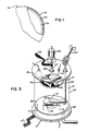
- a solid lubricant coated bearing produced according to a preferred embodiment is comprised of an outer lubricant layer 72 of silver of approximately 1000 ⁇ . This lubricant layer 72 is deposited directly on the substrate 76 whose surface 74 has been treated by shallow ion implantation as will be described below.
- the bearing ball substrate is 5/32 inch in diameter manufactured to the standards of AFBMA Grade 10 with a Rockwell 45N hardness of 70-76 according to ASTM Standard E-18.
- the substrate material is a high speed tool steel conforming to AISI category T-15 and may be purchased under the trade name Vasco Supreme from Teledyne Vasco of Latrobe Pennsylvania. It will be apparent to one skilled in the art that the present invention may be applied to other bearing structures with rolling surfaces such as roller bearings where a cylindrical rolling element is maintained between an inner and outer race, and that the bearing substrate may be composed of other grades of steel or alloys of comparable hardness and finish.
- a lubricant coating system suitable for use with the present invention is comprised of a hollow quartz vacuum cylinder 18 which is sealed by removable aluminum endplates 19 to form a vacuum chamber 20 that will withstand evacuation to a pressure of 10 ⁇ 7 torr.
- Mechanical shafts, electrical wires and piping, to be described below, pass through the endplates 19 by means of gas tight fittings understood in the art.
- the lowermost endplate 19 admits a vacuum pump throat which, by means of diverter valve 58, alternately connects to a rough pump 62 or to a diffusion pump 60.
- the rough pump 60 is mechanical rotary and performs the initial evacuation of the quartz vacuum cylinder from atmospheric pressure.
- the diffusion pump incorporating a cold trap provides the final evacuation required to achieve a hard vacuum of approximately 10 ⁇ 7 torr.
- Attached to and communicating with the inside of the vacuum pump throat 54 is an ion vacuum gauge 62 which provides a measure of the pressures within the quartz vacuum cylinder 18.
- a flow throttle 56 Interposed within the vacuum pump throat between the diverter valve and the lower aluminum endplate 19 is a flow throttle 56 whose operation will be described below.
- a transparent plasma containment cylinder 32 Suspended within the vacuum chamber 20 is a transparent plasma containment cylinder 32 also with removable upper and lower aluminum endplates 33 which form a plasma chamber 21 within the vacuum chamber 20.
- the plasma containment cylinder 32 is not air-tight.
- gases inside the plasma chamber 21 may communicate with gases outside the plasma chamber 21 and within the vacuum chamber 20 by means of the gaps between the plasma containment cylinder 32 and its endplates 33 and by means of ports 31, the latter of which are located predominantly toward the top of the plasma chamber 21.
- gaseous argon admitted by tube 28 though the lower endplate 33 of the plasma chamber, flows generally from the bottom to the top of the plasma chamber 21 and out into the vacuum chamber 20 through ports 31.
- Argon tube 28 extends through the bottom vacuum chamber endplate 19 to metering valve 24 to admit pressurized argon from argon cylinder 22.
- a resistively heated boat 48 holding a small quantity of silver 65, is held above the lower endplate 33, within the plasma chamber 21.
- a heater power supply 52 is connected to the resistively heated boat 48 so as to provide electrical current to heat the boat and melt the silver 65 contained within the boat, as required.
- the temperature of the boat 48 may be raised to the melting point of the lubricant or approximately 960°C.
- auxiliary anode 46 containing an aperture 45, is positioned above the boat 48 so that the aperture 45 is centered around the silver 65.
- the auxiliary anode 46 is affixed to the lower endplate 33 by means of an electrically conducting standoff 47 which in turn is connected by braided anode lead 49 to the positive terminal of the high voltage power supply 50.
- High voltage power supply 50 is a DC power supply capable of supplying up to three thousand volts.
- a shutter 44 affixed to shaft 30 which extents through the upper endplate 33.
- Shaft 30 is in turn connected to flexible shaft 34 which extends through upper endplate 19 and is terminated with knob 12. The rotation of knob 12 serves to swing shutter 44 over or away from aperture 45.
- agitator basket 42 Four inches above the silver 65, and in direct line of sight to the silver 65 when the aperture 45 is uncovered, is agitator basket 42.
- agitator basket 45 is comprised of an aluminum ring 84 connected by spokes 82 to a central hub 80.
- a silver mesh 43 of similar diameter to the ring 84 is affixed to the lower surface of the ring 84 and spokes 82 to form a shallow tray whose walls are the spokes 82, ring 84 and hub 80 and whose bottom is the mesh 43 and which together comprise the agitator basket 42.
- the agitator basket 42 contains the bearing balls 70 during the coating process.
- the mesh 43 is composed of the same material which is to be plated as solid lubricant: silver, so as to reduce surface contamination of the bearing balls 70 during the coating process.
- the agitator basket 42 is affixed to an electrically conducting vertical shaft 37 which is free to rotate and extends through the upper endplate 33 by means of insulated bushing 35 and is connected to motor shaft 38 by means of electrically isolating connector 39.
- Conducting shaft 37 is connected by means of braided cathode lead 40 to the negative terminal of high voltage power supply 50.
- Motor shaft 38 extends upward through upper endplate 19 to agitator motor 14 which is controlled by agitator timer 16. Activation of the agitator motor 14 by the agitator timer 16 results in rotary oscillation of the agitator basket 42 permitting constant relative motion between the agitator basket and the bearing balls 70 as is required to ensure even coating during the coating process.
- thermocouple 10 is attached to the agitator basket 42 to provide a measure of agitator basket 42 and bearing ball 70 temperatures during the coating process. Also, affixed to the lower surface of the upper endplate 33 is a thickness monitor 36 such as is used in the semiconductor industry for measuring metalization rates in the production of integrated circuits.
- the bearing balls 70 are first solvent cleaned in successive ultrasonically agitated baths of alcohol and methylene chloride to remove the instrument oil with which the bearings are coated by the manufacturer. The bearings are then air dried and place in the agitator basket 42 within the plasma chamber.
- the vacuum chamber 20 and plasma chamber 21 are then evacuated to 10 ⁇ 7 torr, filled with high purity argon to atmospheric pressure, and then evacuated again to 10 ⁇ 7 torr as indicated in process block 102.
- the purpose of this procedure is to eliminate, to the extent feasible, stray gas molecules such as nitrogen and oxygen which could combine with the final silver coating to form oxides and nitrites reducing the silver coating's lubricity.
- the agitator timer 16 is activated, oscillating the agitator basket so as to provide uniform processing of the bearing balls 70 during the sputter cleaning process indicated by process block 104.
- high purity gaseous argon is introduced to the plasma chamber 21 raising the pressure to approximately 21 ⁇ m of Hg.
- the flow throttle 56 in the vacuum pump throat 54 prevents saturation of the diffusion pump with the introduced argon stream.
- the high voltage power supply 50 is set to a voltage of 2.5 to 2.8 kvolts creating a high voltage electric field between the auxiliary anode 46 and the agitator basket 42 and bearing balls 70.
- Argon atoms flowing within this field are ionized and the resulting charged argon ions are accelerated by the electric field toward the agitator basket 42 striking it and the bearing balls 70.
- the effect of the high velocity argon ions striking the bearing balls 70 is two fold: 1) surface impurities are cleaned from the bearing balls 70, and 2) the temperature of the bearing balls 70 is increased.
- This sputter cleaning process, indicated by process block 104, is continued for 3-5 minutes at which time the bearing balls temperature has risen to approximately 200-250°C. The duration of the sputter cleaning is critical to the process. Too little cleaning and surface impurities remain to decrease the adhesion of the subsequently applied solid lubricant. Too much cleaning and the surface begins to pit, decreasing the ultimate smoothness of the coated bearing surface.
- the timing of the sputter cleaning process 104 may be adjusted to control the temperature of the bearing balls 70 to be approximately 200°C during the subsequent plating process.
- shutter 44 is placed over the anode aperture 45 and the resistance heated boat 48 is heated to a temperature just under the melting point of the contained silver 65.
- the voltage of the high voltage power supply 50 is increased to 2.8 to 3.0 kvolts to begin the shallow implantation of silver ions, as indicated in process block 106.
- This step 106 and the next step 110 should proceed immediately after the sputter cleaning 104 to reduce the possibility of chemical reaction of the bearing ball activated surfaces with contaminates.
- the voltage applied to the resistance heated boat 48 is now increased to uniformly melt the contained silver 65.
- the shutter 44 is rotated to expose the aperture 45 and the silver 65. Evaporating silver atoms may now flow into the space between the auxiliary anode 46 and the agitator basket 42 where they are ionized and accelerated against the bearing balls 70.
- the anode to cathode voltage is sufficient to implant the accelerating silver ions within the surface of the bearing balls 70. It is believed that the silver ions thus implanted are maintained within a few atomic radius's of the surface of the bearing balls forming a shallow ion implantation layer 74.
- the shallow implantation 106 is continued for 0.5 to 1 minute at which time the voltage is lowered to 2.0 to 2.2 kvolts to begin the plasma assisted ion plating as indicated at process block 110.
- the period of time of the sputter cleaning process 104 may be adjusted slightly so that the bearing balls 70 are at approximately 200° at the time of plating. This temperature promotes an equiaxed plating structure which improves the lubricity of the lubricant coating.
- the pressure is maintained, as is steps 104 and 106, at 18-21 ⁇ m.
- the plating process typically requires approximately 0.5-3 minutes however there may be some variation in deposition rate depending on the equipment's ability to maintain the plating parameters constant. Accordingly, the plating is continued until a layer of approximately 850-1150 ⁇ is obtained as may be indirectly monitored by the thickness gauge 36.
- the ion plated layer 72 so produced may have a uniformity to within ⁇ 100 ⁇ .
- the plating process produces a plated layer of substantially pure solid lubricant.
- the agitator timer 16 is turned off, and the plating chamber is again evacuated to 10 ⁇ 7 torr, as indicated at process block 112.
- the bearing balls 70 are allowed to cool to room temperature under vacuum to prevent the formation of oxides and nitrites which formation would be accelerated at the high plating temperatures.
- bearing balls 70 are assembled into bearings 150 comprised of an outer grooved race 162 and an inner grooved race 164.
- the inner grooved race 164 is split into two equal halves along its circumferential groove to permit the insertion of twelve bearing balls 70 into the races 162 and 164.
- the inner and outer races 162 and 164 are constructed of high speed tool steel
- a bearing 150 is placed on either end of the bearing shaft 158.
- a molybdenum spring 161 presses against front and rear bearing retainers 163 which seat against the outer bearing races 162 to provide the assembled bearings 150 with axial preload.
- One end of the bearing shaft 158 is rigidly affixed to the center of a disk shaped anode 156 and also to a tubular copper rotor sleeve 160 which surrounds the length of the bearing shaft 158 and serves as an armature for an induction motor (not shown) which provides torque to the bearing shaft 158 and which thereby spins the anode 156
- This entire anode assembly is contained in a glass envelope 154 which may be evacuated to 10 ⁇ 9 torr.
- a cathode 152 Directed toward the surface of the anode 156 and also within the glass envelope 154 is a cathode 152 which emits a stream of high energy electrons toward the face of the spinning anode 156 as is understood in the art.
- the solid lubricant silver was applied solely to the rolling surface of a bearing balls and not to the surface of either of the races.
- the rolling surfaces of either or both of the races may be coated in addition to or in lieu of the coating on the bearing ball provided the combined lubricant layer between any two contacting surfaces is maintained to approximately 700-1500 ⁇ .
- the shallow ion implantation technique may be used with other solid lubricants, such as gold and lead, to improve adherence and reduce lubricant exfoliation.
- solid lubricants such as gold and lead
- Indium and tin are other possible alternatives.
- other inert gases such as Helium may be used in place of the Argon for sputtering and to assist the coating process.
Landscapes
- Chemical & Material Sciences (AREA)
- Engineering & Computer Science (AREA)
- Mechanical Engineering (AREA)
- Chemical Kinetics & Catalysis (AREA)
- Materials Engineering (AREA)
- Metallurgy (AREA)
- Organic Chemistry (AREA)
- General Engineering & Computer Science (AREA)
- Rolling Contact Bearings (AREA)
- Physical Vapour Deposition (AREA)
Applications Claiming Priority (2)
| Application Number | Priority Date | Filing Date | Title |
|---|---|---|---|
| US07/313,182 US4956858A (en) | 1989-02-21 | 1989-02-21 | Method of producing lubricated bearings |
| US313182 | 1999-05-18 |
Publications (3)
| Publication Number | Publication Date |
|---|---|
| EP0384705A2 true EP0384705A2 (de) | 1990-08-29 |
| EP0384705A3 EP0384705A3 (de) | 1992-05-27 |
| EP0384705B1 EP0384705B1 (de) | 1995-05-03 |
Family
ID=23214703
Family Applications (1)
| Application Number | Title | Priority Date | Filing Date |
|---|---|---|---|
| EP90301805A Expired - Lifetime EP0384705B1 (de) | 1989-02-21 | 1990-02-20 | Verfahren zur Herstellung von geschmierten Lagern |
Country Status (4)
| Country | Link |
|---|---|
| US (1) | US4956858A (de) |
| EP (1) | EP0384705B1 (de) |
| JP (1) | JP2680158B2 (de) |
| DE (1) | DE69019032T2 (de) |
Cited By (5)
| Publication number | Priority date | Publication date | Assignee | Title |
|---|---|---|---|---|
| GB2238089A (en) * | 1989-09-28 | 1991-05-22 | Daido Metal Co | Method of producing a plain bearing |
| EP0488311A1 (de) * | 1990-11-28 | 1992-06-03 | Kabushiki Kaisha Toshiba | Verfahren zur Herstellung einer Drehanoden-Röntgenröhre und Vorrichtung zu ihrer Herstellung |
| US5742987A (en) * | 1996-09-11 | 1998-04-28 | Alliedsignal Inc. | Buckle for use with a pretensioner |
| DE19721219A1 (de) * | 1997-05-21 | 1998-11-26 | Bultykhanova Natalie | Zahnrad und Herstellverfahren |
| CN108385074A (zh) * | 2018-03-22 | 2018-08-10 | 深圳大学 | 一种氮元素注入方法及其改性刀具、模具 |
Families Citing this family (19)
| Publication number | Priority date | Publication date | Assignee | Title |
|---|---|---|---|---|
| US5150398A (en) * | 1988-07-06 | 1992-09-22 | Kabushiki Kaisha Toshiba | Bearing and rotary anode X-ray tube employing the bearing |
| JP2850353B2 (ja) * | 1989-03-17 | 1999-01-27 | 日本精工株式会社 | ころがり軸受 |
| CN1024065C (zh) * | 1990-10-19 | 1994-03-16 | 株式会社东芝 | 旋转阳极型x射线管 |
| US5292596A (en) * | 1991-05-13 | 1994-03-08 | United Technologies Corporation | Force-transmitting surfaces of titanium protected from pretting fatigue by a coating of Co-Ni-Fe |
| US5468357A (en) * | 1994-12-27 | 1995-11-21 | Hughes Missile Systems Company | Densification of porous articles by plasma enhanced chemical vapor infiltration |
| US5887985A (en) * | 1997-07-24 | 1999-03-30 | Thermo Cardiosystems Inc. | Wear-resistant bearings |
| US5991361A (en) * | 1998-01-26 | 1999-11-23 | General Electric Company | Bearing assembly for X-ray tube |
| US7250196B1 (en) | 1999-10-26 | 2007-07-31 | Basic Resources, Inc. | System and method for plasma plating |
| US6503379B1 (en) * | 2000-05-22 | 2003-01-07 | Basic Research, Inc. | Mobile plating system and method |
| US6521104B1 (en) * | 2000-05-22 | 2003-02-18 | Basic Resources, Inc. | Configurable vacuum system and method |
| US20030180450A1 (en) * | 2002-03-22 | 2003-09-25 | Kidd Jerry D. | System and method for preventing breaker failure |
| US7004635B1 (en) * | 2002-05-17 | 2006-02-28 | Varian Medical Systems, Inc. | Lubricated ball bearings |
| US20050126497A1 (en) * | 2003-09-30 | 2005-06-16 | Kidd Jerry D. | Platform assembly and method |
| US20080095316A1 (en) * | 2006-10-09 | 2008-04-24 | General Electric Company | Anode assembly bearing apparatus for an x-ray device |
| US8240923B2 (en) * | 2008-01-15 | 2012-08-14 | The Timken Company | X-ray tube rotating anode assembly bearing |
| JP5988823B2 (ja) * | 2012-10-19 | 2016-09-07 | 株式会社日立製作所 | 回転陽極x線管装置およびx線撮像装置 |
| DE102020209897A1 (de) | 2020-08-05 | 2022-02-10 | Minebea Mitsumi Inc. | Verfahren zum Herstellen von Wälzkörpern, Wälzlager und Drehanode für eine Röntgenröhre |
| CN117845179A (zh) * | 2022-09-30 | 2024-04-09 | 武汉联影医疗科技有限公司 | 用于提高x射线管轴承性能的方法、轴承及x射线管 |
| CN116200716B (zh) * | 2023-02-24 | 2024-06-14 | 安徽泰臻真空科技有限公司 | 一种真空镀膜装置 |
Family Cites Families (16)
| Publication number | Priority date | Publication date | Assignee | Title |
|---|---|---|---|---|
| GB1413813A (en) * | 1972-09-19 | 1975-11-12 | Atomic Energy Authority Uk | Surface treatment of metals |
| US4097759A (en) * | 1976-07-21 | 1978-06-27 | Picker Corporation | X-ray tube |
| US4097760A (en) * | 1976-07-21 | 1978-06-27 | Picker Corporation | X-ray tube having bearing lubrication |
| JPS5557717A (en) * | 1978-10-25 | 1980-04-28 | Koyo Seiko Co Ltd | Rolling bearing |
| NL8101931A (nl) * | 1981-04-21 | 1982-11-16 | Philips Nv | Inrichting voorzien van een lager. |
| JPS57192257A (en) * | 1981-05-22 | 1982-11-26 | Hitachi Ltd | Manufacture of bearing construction with solid lubricant |
| JPS58181863A (ja) * | 1982-04-14 | 1983-10-24 | Sumitomo Electric Ind Ltd | 表面処理方法 |
| JPS6057014A (ja) * | 1983-09-08 | 1985-04-02 | Koyo Seiko Co Ltd | ころがり軸受 |
| US4569070A (en) * | 1983-09-19 | 1986-02-04 | General Electric Company | Thermally compensated x-ray tube bearings |
| JPS59189925U (ja) * | 1984-03-29 | 1984-12-17 | 光洋精工株式会社 | ころがり軸受 |
| JPS6155410A (ja) * | 1984-08-27 | 1986-03-19 | Nippon Telegr & Teleph Corp <Ntt> | 固体潤滑軸受 |
| JPH064909B2 (ja) * | 1985-05-28 | 1994-01-19 | 理化学研究所 | 金 型 |
| JPS62200096A (ja) * | 1986-02-25 | 1987-09-03 | Sanyo Electric Co Ltd | 潤滑膜の形成方法 |
| US4821385A (en) * | 1986-07-29 | 1989-04-18 | Koyo Seiko Co., Ltd. | Method of making a bearing |
| JPH0726054B2 (ja) * | 1987-06-24 | 1995-03-22 | 三井石油化学工業株式会社 | 樹脂分散物 |
| JPH098046A (ja) * | 1995-06-20 | 1997-01-10 | Nippon Avionics Co Ltd | 半導体チップの突起電極形成方法 |
-
1989
- 1989-02-21 US US07/313,182 patent/US4956858A/en not_active Expired - Lifetime
-
1990
- 1990-02-16 JP JP2034055A patent/JP2680158B2/ja not_active Expired - Fee Related
- 1990-02-20 DE DE69019032T patent/DE69019032T2/de not_active Expired - Lifetime
- 1990-02-20 EP EP90301805A patent/EP0384705B1/de not_active Expired - Lifetime
Cited By (7)
| Publication number | Priority date | Publication date | Assignee | Title |
|---|---|---|---|---|
| GB2238089A (en) * | 1989-09-28 | 1991-05-22 | Daido Metal Co | Method of producing a plain bearing |
| GB2238089B (en) * | 1989-09-28 | 1994-04-06 | Daido Metal Co | Composite bearings |
| EP0488311A1 (de) * | 1990-11-28 | 1992-06-03 | Kabushiki Kaisha Toshiba | Verfahren zur Herstellung einer Drehanoden-Röntgenröhre und Vorrichtung zu ihrer Herstellung |
| US5298293A (en) * | 1990-11-28 | 1994-03-29 | Kabushiki Kaisha Toshiba | Method of manufacturing a rotary anode type X-ray tube |
| US5742987A (en) * | 1996-09-11 | 1998-04-28 | Alliedsignal Inc. | Buckle for use with a pretensioner |
| DE19721219A1 (de) * | 1997-05-21 | 1998-11-26 | Bultykhanova Natalie | Zahnrad und Herstellverfahren |
| CN108385074A (zh) * | 2018-03-22 | 2018-08-10 | 深圳大学 | 一种氮元素注入方法及其改性刀具、模具 |
Also Published As
| Publication number | Publication date |
|---|---|
| JP2680158B2 (ja) | 1997-11-19 |
| EP0384705A3 (de) | 1992-05-27 |
| JPH02267265A (ja) | 1990-11-01 |
| EP0384705B1 (de) | 1995-05-03 |
| US4956858A (en) | 1990-09-11 |
| DE69019032D1 (de) | 1995-06-08 |
| DE69019032T2 (de) | 1996-01-18 |
Similar Documents
| Publication | Publication Date | Title |
|---|---|---|
| EP0384705B1 (de) | Verfahren zur Herstellung von geschmierten Lagern | |
| EP0389799A2 (de) | Titankarbid-Überzug für Lagerteile | |
| US5482602A (en) | Broad-beam ion deposition coating methods for depositing diamond-like-carbon coatings on dynamic surfaces | |
| US4877505A (en) | Method and apparatus for application of coatings on substrates | |
| CN1024065C (zh) | 旋转阳极型x射线管 | |
| KR101699774B1 (ko) | 다이아몬드 라이크 카본 피막 형성 부재 및 그 제조 방법 | |
| JPWO2012036238A1 (ja) | 血液と接触する表面の血小板付着性を減少させる医療用機器の製造方法 | |
| JPH0154433B2 (de) | ||
| US5061512A (en) | Method of producing lubricated bearings | |
| JPH01279119A (ja) | 機械部材 | |
| WO1995012693A9 (en) | Method for producing diamond-like carbon layers | |
| GB2458518A (en) | An aerospace bearing | |
| CN109504945A (zh) | 一种空间环境用长效抗菌固体润滑膜层及其制备方法 | |
| US4988534A (en) | Titanium carbide coating of bearing components | |
| US4962519A (en) | Lubricated bearing retainer for X-ray tube | |
| US6582531B2 (en) | X-ray tube and method of manufacture | |
| US7004635B1 (en) | Lubricated ball bearings | |
| US4305631A (en) | High temperature bearing bakeout process | |
| JP2006261096A (ja) | 軸受けを有する放射線放出装置及び製造方法 | |
| US7505564B2 (en) | Composite coating for improved wear resistance for x-ray tube bearings | |
| JP3729217B2 (ja) | 転がり軸受の玉への固体潤滑膜形成方法 | |
| US7492869B1 (en) | Titanium carbide plus silver coated balls for x-ray tube bearings | |
| JP2930255B2 (ja) | 回転陽極型x線管 | |
| US7397897B2 (en) | Composite coating for improved wear resistance for x-ray tube bearings | |
| JP2546839B2 (ja) | 転がり軸受要素 |
Legal Events
| Date | Code | Title | Description |
|---|---|---|---|
| PUAI | Public reference made under article 153(3) epc to a published international application that has entered the european phase |
Free format text: ORIGINAL CODE: 0009012 |
|
| AK | Designated contracting states |
Kind code of ref document: A2 Designated state(s): DE FR IT NL |
|
| PUAL | Search report despatched |
Free format text: ORIGINAL CODE: 0009013 |
|
| AK | Designated contracting states |
Kind code of ref document: A3 Designated state(s): DE FR IT NL |
|
| 17P | Request for examination filed |
Effective date: 19921109 |
|
| 17Q | First examination report despatched |
Effective date: 19940208 |
|
| GRAA | (expected) grant |
Free format text: ORIGINAL CODE: 0009210 |
|
| AK | Designated contracting states |
Kind code of ref document: B1 Designated state(s): DE FR IT NL |
|
| PG25 | Lapsed in a contracting state [announced via postgrant information from national office to epo] |
Ref country code: FR Effective date: 19950503 Ref country code: NL Free format text: LAPSE BECAUSE OF FAILURE TO SUBMIT A TRANSLATION OF THE DESCRIPTION OR TO PAY THE FEE WITHIN THE PRESCRIBED TIME-LIMIT Effective date: 19950503 Ref country code: IT Free format text: LAPSE BECAUSE OF FAILURE TO SUBMIT A TRANSLATION OF THE DESCRIPTION OR TO PAY THE FEE WITHIN THE PRE;WARNING: LAPSES OF ITALIAN PATENTS WITH EFFECTIVE DATE BEFORE 2007 MAY HAVE OCCURRED AT ANY TIME BEFORE 2007. THE CORRECT EFFECTIVE DATE MAY BE DIFFERENT FROM THE ONE RECORDED.SCRIBED TIME-LIMIT Effective date: 19950503 |
|
| REF | Corresponds to: |
Ref document number: 69019032 Country of ref document: DE Date of ref document: 19950608 |
|
| EN | Fr: translation not filed | ||
| NLV1 | Nl: lapsed or annulled due to failure to fulfill the requirements of art. 29p and 29m of the patents act | ||
| PLBE | No opposition filed within time limit |
Free format text: ORIGINAL CODE: 0009261 |
|
| STAA | Information on the status of an ep patent application or granted ep patent |
Free format text: STATUS: NO OPPOSITION FILED WITHIN TIME LIMIT |
|
| 26N | No opposition filed | ||
| PGFP | Annual fee paid to national office [announced via postgrant information from national office to epo] |
Ref country code: DE Payment date: 20090331 Year of fee payment: 20 |
|
| PG25 | Lapsed in a contracting state [announced via postgrant information from national office to epo] |
Ref country code: DE Free format text: LAPSE BECAUSE OF EXPIRATION OF PROTECTION Effective date: 20100220 |