EP0384885B1 - Distributeur pour exemplaires isolés - Google Patents
Distributeur pour exemplaires isolés Download PDFInfo
- Publication number
- EP0384885B1 EP0384885B1 EP90810044A EP90810044A EP0384885B1 EP 0384885 B1 EP0384885 B1 EP 0384885B1 EP 90810044 A EP90810044 A EP 90810044A EP 90810044 A EP90810044 A EP 90810044A EP 0384885 B1 EP0384885 B1 EP 0384885B1
- Authority
- EP
- European Patent Office
- Prior art keywords
- conveyor belt
- transfer device
- sensor
- conveyor
- transfer apparatus
- Prior art date
- Legal status (The legal status is an assumption and is not a legal conclusion. Google has not performed a legal analysis and makes no representation as to the accuracy of the status listed.)
- Expired - Lifetime
Links
- 230000033001 locomotion Effects 0.000 claims description 3
- 230000002441 reversible effect Effects 0.000 claims description 2
- 239000011324 bead Substances 0.000 claims 1
- 235000019219 chocolate Nutrition 0.000 description 2
- 230000004888 barrier function Effects 0.000 description 1
- 230000005540 biological transmission Effects 0.000 description 1
- 238000010276 construction Methods 0.000 description 1
- 238000004519 manufacturing process Methods 0.000 description 1
- 230000001360 synchronised effect Effects 0.000 description 1
Images


Classifications
-
- B—PERFORMING OPERATIONS; TRANSPORTING
- B65—CONVEYING; PACKING; STORING; HANDLING THIN OR FILAMENTARY MATERIAL
- B65G—TRANSPORT OR STORAGE DEVICES, e.g. CONVEYORS FOR LOADING OR TIPPING, SHOP CONVEYOR SYSTEMS OR PNEUMATIC TUBE CONVEYORS
- B65G47/00—Article or material-handling devices associated with conveyors; Methods employing such devices
- B65G47/74—Feeding, transfer, or discharging devices of particular kinds or types
- B65G47/84—Star-shaped wheels or devices having endless travelling belts or chains, the wheels or devices being equipped with article-engaging elements
- B65G47/846—Star-shaped wheels or wheels equipped with article-engaging elements
Definitions
- the present invention relates to a distributor of individual pieces according to the preamble of patent claim 1.
- a transfer device is provided with a plurality of suction trolleys, which are arranged by means of arms about a central axis.
- Each suction trolley is provided with a suction device and a valve tappet for controlling the vacuum, which is actuated by the single piece to be picked up, so that the suction air is released and the single piece is held in the suction device.
- the suction cups are designed so that they can be rotated by 90 degrees so that the individual pieces located on the conveyor belt of the feed section maintain their position when they are released onto the conveyor belt of the receiving section.
- the known transfer device does indeed cause the individual pieces to be transferred correctly from one encoder machine to a cartoning machine, but is very complex with regard to the suction cups, which are rotatable by 90 ° and work with vacuum.
- the present invention is therefore based on the object of providing a distributor of small individual pieces with a less expensive transfer device.
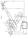
- the distributor shown in Fig. 1 has a conveyor track 1, which can be set in motion between two conveyors 2 and 3, the conveyor tracks 2 'and 3' of the conveyor 2 or 3 and the conveyor track 1, at least approximately in one plane are located.
- a single piece 4, for example a packaged chocolate bar, lies on the conveyor track 1.
- a transfer device 5 is arranged, which has an impeller 6, a servo motor 7 and one Encoder 8 comprises, which is connected to a processor or computer 9, which also supplies signals for a servo motor 10 of the conveyor 2 and for a servo motor 11 of the conveyor 3.
- a sensor 12 is arranged directly in front of the transfer device 5 in the direction of movement of the conveyor track 1; and preferably about 2 piece lengths in front of it is a second sensor 13, the processor 9 being connected to these sensors 12 and 13 as well as to a further encoder 14 synchronized with the conveyor track 1.
- the conveyors 2 and 3 and the transfer device 5 are shown with some details to show that the conveyors each have an auxiliary conveyor 15, 15 '.
- the conveyor 2 and the auxiliary conveyor 15 have a common roller 16 with four grooves or grooves, two with the inner diameter D and two with the inner diameter d, D being greater than d.
- Conveyors 2 and / or 3 preferably have no conveyor belts, but two round belts each, of which only one round belt 18 or 19 is visible in FIG. 2, which are inserted into the grooves with diameter D.
- auxiliary conveyor 15, 15 'each comprise two chain belts, which are inserted into the grooves with the diameter d, and of which only one chain belt 20 or 21 is visible in FIG. 2.
- These Chain belts are provided with holding links 22 and 23, which are preferably distributed at regular intervals.
- the transfer device 5 shown in FIG. 2 has an impeller with six blades, the edge of the blade 24 being in the vicinity of a single piece 4 lying on the conveyor track 1.
- the holding members 22 are outside the area defined by the round belts 18, 18 '.
- the holding links 22 according to FIG. 2 are located within the area mentioned to indicate that both types of construction are possible, with instead of round and chain belts e.g. V-belts or flat belts could also be used.
- Fig. 3 several individual pieces 4 are shown both on the conveyor track or the conveyor belt 1 and on the pairs of belts 18, 18 'and 19, 19'. From the transfer device, only two wings 25, 25 'are visible in Fig. 3.
- the distance between the axis 26 of the impeller and the outer edge of a Wing 24 is slightly smaller than the distance between this axis 26 and the area determined by the round belts 18, 18 'on which the individual pieces 4 lie.
- the holding members 22, 22 'on the outside with respect to the round belts 18, 18'.
- the wings each have a central slot 27, 27 'to create a free space for a guide bar 28 which is arranged perpendicular to the axis 26 and slightly above the individual pieces 4.
- the optional guide bar 28 is not shown in FIGS. 1 to 3. This guide bar can be straight or partially curved.
- the distributor according to FIGS. 1 to 4 now works as follows: First of all, it should be noted that the distributor can also work with only one of the conveyors 2 or 3, that the sensor 12 is omitted for some applications, and that the impeller must have at least two blades or a blade and a counterweight.
- the processor 9 can determine the position of a reference point of the conveyor track 1 at any moment by means of the signals supplied by the encoder 14.
- the processor 9 can use the signals supplied by the sensor 13 (FIG. 1) to determine when the front edge of a single piece 4 is just at the sensor 13 passes by. With this information, the processor 9 can supply the encoder 8 with signals which controls the servo motor 7 in such a way that a wing 24 (FIG. 2) of the transfer device 5 gives an impact to a single piece 4 when it is in a centered position with respect to it located on the conveyor track 2 ', so that the single piece lands on the conveyor track 2' and is held by the holding members 22.
- the processor 9 can also control the servo motor 10 in such a way that the individual pieces 4 arrive at the conveyor track 2 'at a certain cycle or at predetermined intervals.
- the sensor 12 serves to detect the position of the pieces on the feed belt or the conveyor track 1. If after switching on the distributor there are pieces between the two sensors 12 and 13 whose position is not known, they are detected by the sensor 12 and then, for example encountered on the conveyor track 3 'by rotating the impeller 6 in the other direction.
- the processor 9 can perform a so-called software shift register function as follows: As soon as the sensor 13 detects a beginning of a piece, a one is written into the register, which is currently displayed. Its address is recorded in a so-called address flag and the counter is deleted. With each cycle from the encoder 14, the counter is increased by one and the reader and writer are shifted up by one address. Registered the Sensor 13 again a piece start, the counter content is stored under the address that is in the address flag, the new recorder address is recorded in the address flag and the counter is deleted. After a shift register length, the reader now reads the values that the writer has written into it.
- the transfer device runs at a speed at which one revolution corresponds to the average distance between the pieces. The corresponding value is subtracted from the counter and added to the address in the address flag. The one in the shift register is now saved in this new address in the shift register. It should be noted that the impeller should rotate continuously and should not be reduced to zero speed.
- the distributor can have, for example, three proximity switches, which are used when positioning the motors when switching on or during a reset.
- the transfer device has an open belt drive with two rollers 30, 31, at least one pin 33 being attached to the belt 32.
- the belt drive according to FIG. 5 is arranged transversely over the conveyor track 1, preferably in such a way that the axes of the rollers 30, 31 run parallel to the conveyor track 1.
- the belt drive works in such a way that at a predetermined time the pin 33 moves the piece 4 from the center of the conveyor track 1 to the conveyor track 2 'or 3'.
- the distributor according to the invention can not only work with one of the conveyors 2 or 3, but also when the power is divided between the two conveyors.
- a storage function is also possible in that pieces that are on one of the conveyor tracks 2 'or 3' are moved via the stationary conveyor track 1 to the other conveyor track 3 'or 2'.
- the distributor is reversible, which means that the conveyor track 1 can serve not only as a feed track but also as a receiving track.
- Light barriers can serve as sensors, for example.
Landscapes
- Engineering & Computer Science (AREA)
- Mechanical Engineering (AREA)
- Attitude Control For Articles On Conveyors (AREA)
- Control Of Conveyors (AREA)
- Branching, Merging, And Special Transfer Between Conveyors (AREA)
- Feeding Of Articles To Conveyors (AREA)
- Specific Conveyance Elements (AREA)
- Intermediate Stations On Conveyors (AREA)
- Special Conveying (AREA)
Claims (9)
- Distributeur d'articles individuels empaquetés, comportant un dispositif rotatif de transfert pour transférer, sur un second chemin de transport, des articles individuels qui sont entraînés en position couchée sur un premier chemin de transport, l'axe de rotation du dispositif rotatif de transfert se trouvant dans un plan parallèle au premier chemin de transport (1), caractérisé en ce que
le dispositif de transfert se trouve au milieu au-dessus d'une région du premier chemin de transport (1) au niveau de laquelle sont disposés, respectivement à gauche et à droite de ce premier chemin de transport (1) et perpendiculairement à lui, un deuxième (2′) et un troisième chemin de transport (3′),
il est prévu un processeur (9) qui délivre des signaux pour la commande du dispositif de transfert (5) et de servomoteurs (10; 11) assurant respectivement l'entraînement du deuxième et du troisième chemin de transport (2′; 3′), pour qu'un article individuel (4) puisse être placé, à partir du milieu du premier chemin de transport (1) sur le deuxième ou sur le troisième chemin de transport (2′; 3′), et
ou bien le dispositif de transfert (5) comprend une roue à ailettes (6) qui peut tourner autour d'un axe de rotation et qui comporte au moins une ailette (24) disposée radialement, dont le bord présente au moins une entaille (27) pour laisser la place libre pour une barre de guidage (28) dont une partie au moins se trouve au-dessus de l'espace prévu pour le passage des articles individuels (4) et est disposée perpendiculairement à l'axe de rotation (26) de la roue à ailettes, ou bien le dispositif de transfert est une courroie d'entraînement qui est disposée transversalement au-dessus du premier chemin de transport (1) et qui est munie d'au moins une broche (33) pour la translation des articles individuels (4). - Distributeur selon la revendication 1, caractérisé en ce que la courroie d'entraînement comprend deux rouleaux (30, 31) dont les axes s'étendent parallèlement au premier chemin de transport (1) et définissent un plan, la distance entre ce plan et le plan de transport du premier chemin de transport étant approximativement égale ou inférieure au diamètre des rouleaux (30, 31).
- Distributeur selon la revendication 1 ou 2, caractérisé en ce qu'il est réversible et rend possible une fonction d'accumulation pour que des articles individuels, qui se trouvent sur le chemin de transport gauche ou droit (2′; 3′), soient transférés sur l'autre chemin de transport (3′ ou 2′), de l'autre côté du premier chemin de transport (1) immobilisé.
- Distributeur selon l'une quelconque des revendications 1 à 3, caractérisé en ce que le deuxième et/ou le troisième chemin de transport (2′; 3′) comprend deux courroies parallèles entraînées (18, 18′; 19, 19′).
- Distributeur selon la revendication 4, caractérisé en ce que le deuxième et/ou le troisième chemin de transport (2′; 3′) fait partie d'un transporteur (2, 3) qui comprend un transporteur auxiliaire (15; 15′) dont les courroies (20; 21) sont munies d'organes de retenue (22; 23).
- Distributeur selon l'une quelconque des revendications 1 à 5, caractérisé en ce que le premier chemin de transport (1) est accouplé cinématiquement à un codeur (14).
- Distributeur selon la revendication 6, caractérisé en ce que le processeur (9) détermine à tout moment, par les signaux délivrés par ledit premier codeur (14), la position d'un point de référence du premier chemin de transport (1), en ce que le processeur (9) détermine, par les signaux délivrés par un premier détecteur (13), le moment auquel un article individuel (4) passe juste en regard de ce premier détecteur (13), et en ce qu'à partir de ces indications, le processeur (9) délivre à un second codeur (8) des signaux pour la commande du dispositif de transfert (5).
- Distributeur selon la revendication 7, caractérisé en ce qu'un second détecteur (12) raccordé au processeur (9) est disposé immédiatement avant le dispositif de transfert (5) dans le sens de mouvement du premier chemin de transport (1), en ce que le premier détecteur (13) se trouve à une distance du second détecteur (12) qui sert à l'acquisition de la position des articles individuels sur le premier chemin de transport (1) lorsque, après la mise en marche du distributeur, il se trouve, entre les deux détecteurs (12, 13), des articles individuels dont la position est inconnue, et en ce que de tels articles individuels sont détectés par le second détecteur (12) et poussés sur un chemin de transport latéral (3′) par rotation du dispositif de transfert (5) dans l'autre sens.
- Distributeur selon la revendication 6, caractérisé en ce que la sortie d'au moins un détecteur (13), qui délivre un signal pour l'acquisition de la position d'un article individuel (4) sur le premier chemin de transport (1), et la sortie dudit codeur (14) sont raccordées au processeur (9).
Applications Claiming Priority (2)
| Application Number | Priority Date | Filing Date | Title |
|---|---|---|---|
| CH606/89 | 1989-02-20 | ||
| CH60689 | 1989-02-20 |
Publications (3)
| Publication Number | Publication Date |
|---|---|
| EP0384885A2 EP0384885A2 (fr) | 1990-08-29 |
| EP0384885A3 EP0384885A3 (fr) | 1991-01-09 |
| EP0384885B1 true EP0384885B1 (fr) | 1994-07-06 |
Family
ID=4190891
Family Applications (1)
| Application Number | Title | Priority Date | Filing Date |
|---|---|---|---|
| EP90810044A Expired - Lifetime EP0384885B1 (fr) | 1989-02-20 | 1990-01-19 | Distributeur pour exemplaires isolés |
Country Status (5)
| Country | Link |
|---|---|
| US (1) | US5052542A (fr) |
| EP (1) | EP0384885B1 (fr) |
| JP (1) | JPH02233416A (fr) |
| DE (1) | DE59006330D1 (fr) |
| ES (1) | ES2055393T3 (fr) |
Cited By (1)
| Publication number | Priority date | Publication date | Assignee | Title |
|---|---|---|---|---|
| CN1648023B (zh) * | 2004-01-28 | 2011-01-26 | E.C.H.威尔股份有限公司 | 纸令横向传送的方法和器械以及设备 |
Families Citing this family (40)
| Publication number | Priority date | Publication date | Assignee | Title |
|---|---|---|---|---|
| WO1992018259A1 (fr) * | 1991-04-15 | 1992-10-29 | Lorillard Tobacco Company | Systeme de tri de paquets de cigarettes |
| US5275272A (en) * | 1993-04-06 | 1994-01-04 | Sandvik Process Systems, Inc. | Conveyor system with article diverting mechanism |
| AUPN244495A0 (en) * | 1995-04-13 | 1995-05-11 | 3M Australia Pty Limited | Sorting device and method |
| DE19542846A1 (de) * | 1995-11-17 | 1997-05-22 | Spuehl Ag | Federtransporteinrichtung mit Servo-Antrieb |
| DE19736567C1 (de) * | 1997-08-22 | 1998-11-26 | Select Ingenieurgesellschaft F | Einrichtung zu einer merkmalsbezogenen Sortierung von Produkten und Verfahren zu deren Betrieb |
| EP0904854B1 (fr) * | 1997-09-15 | 2002-11-13 | Siemens Aktiengesellschaft | Dispositif de triage d'articles |
| DE19827235C1 (de) | 1998-06-18 | 2000-02-10 | Bell & Howell Co | Postbearbeitungsmaschine |
| DE19851780A1 (de) * | 1998-11-10 | 2000-05-11 | Will E C H Gmbh & Co | Vorrichtung zum Ausschleusen von Blattlagen aus einer Förderlinie |
| US6264042B1 (en) * | 1999-11-15 | 2001-07-24 | United Parcel Service Of America, Inc. | Bilateral sorter |
| CA2302095C (fr) * | 2000-03-24 | 2005-06-14 | Gemofor Inc. | Systeme de transbordement du bois d'oeuvre |
| AU2001246958A1 (en) | 2000-03-31 | 2001-10-08 | Tomra Systems Asa | Apparatuses for the conveying, lifting and sorting of articles |
| DE50206687D1 (de) * | 2002-11-29 | 2006-06-08 | Mueller Martini Holding Ag | Einrichtung zur Herstellung eines gebundenen Druckerzeugnisses |
| NZ534244A (en) | 2004-07-20 | 2007-05-31 | Foodcap Int Ltd | Product distribution methods and apparatus |
| AU2005294891B2 (en) | 2004-10-15 | 2013-01-31 | Foodcap International Limited | Container, lid and clip therefor |
| ES2530521T3 (es) | 2004-10-15 | 2015-03-03 | Foodcap Int Ltd | Procedimientos y aparato para la regulación térmica de productos perecederos |
| ES2624002T3 (es) * | 2004-10-18 | 2017-07-12 | Foodcap International Limited | Método para el procesamiento y distribución de productos cárnicos |
| SE527834C2 (sv) * | 2004-11-10 | 2006-06-13 | Norden Pac Dev Ab | Anordning och förfarande för kartoneringsmaskin |
| SE527878C2 (sv) * | 2004-11-30 | 2006-07-04 | Tetra Laval Holdings & Finance | Anordning för uttag av föremål framförda på en transportbana |
| DK1947617T3 (en) | 2005-01-25 | 2016-11-28 | Tomra Systems Asa | Polet system for installation in return slot |
| MXPA05009225A (es) * | 2005-08-30 | 2007-02-27 | Grupo Bimbo Sa De Cv | Alimentador automatico de platos y/o moldes de productos de pasteleria al tren de formado. |
| NL1030192C2 (nl) * | 2005-10-14 | 2007-04-17 | Stork Townsend Bv | Inrichting en werkwijze voor het overzetten van langgerekte voedselproducten. |
| DE102012003604B4 (de) * | 2012-02-21 | 2025-04-30 | Müller Martini Holding AG | Vorrichtung zum Zuführen von Buchblocks in den Einfuhrkanal einer Weiterverarbeitungseinrichtung |
| CN102897520A (zh) * | 2012-10-15 | 2013-01-30 | 江苏圆通农机科技有限公司 | 一种刮板拨料器 |
| US9327914B1 (en) * | 2013-08-22 | 2016-05-03 | Millard Manufacturing Corp. | Rotary sweep arm system |
| CN103552836B (zh) * | 2013-10-21 | 2016-01-20 | 江苏永钢集团有限公司 | 一种窑粉灰生产装置 |
| JP6309305B2 (ja) * | 2014-02-26 | 2018-04-11 | 大和製衡株式会社 | 選別装置 |
| CN105415871A (zh) * | 2015-11-27 | 2016-03-23 | 荣昌精密机械(苏州)有限公司 | 一种印刷流水线机构 |
| GB201703134D0 (en) * | 2017-02-27 | 2017-04-12 | Beers Uk Ltd | Dispensing apparatus |
| JP6930720B2 (ja) * | 2017-04-21 | 2021-09-01 | 一壽 大月 | 新型フリートレイ式選果設備 |
| CN108177962A (zh) * | 2017-12-08 | 2018-06-19 | 桐乡胜辉精密机械有限公司 | 一种工件送料机构 |
| FR3082127B1 (fr) * | 2018-06-12 | 2021-12-03 | Prot Decoration Conditionnement P D C Europe | Installation de selection d'objets defilant sur une ligne de transfert |
| AU2019368359B2 (en) * | 2018-10-25 | 2025-10-02 | And Y Knot Innovation And Sales Inc. | Stacking and packaging device |
| CN109592308A (zh) * | 2018-11-30 | 2019-04-09 | 河南易成新能源股份有限公司 | 机加自动送料装置及方法 |
| FR3098208B1 (fr) * | 2019-07-01 | 2023-10-27 | Semso | Dispositif de convoyage de produits filiformes a grande vitesse et procede de mise en oeuvre |
| JP7473387B2 (ja) * | 2020-05-12 | 2024-04-23 | 株式会社前川製作所 | ワーク移送装置 |
| CN112811148B (zh) * | 2020-12-29 | 2022-06-21 | 江苏华工激光科技有限公司 | 一种分料装置 |
| CN113213061A (zh) * | 2021-05-13 | 2021-08-06 | 湖北瑞佳不锈钢有限公司 | 不锈钢壶体传输装置 |
| WO2023015385A1 (fr) | 2021-08-11 | 2023-02-16 | And Y Knot Innovation And Sales Inc. | Dispositif et système de transport pour emballer des articles allongés |
| DE102021123023A1 (de) | 2021-09-06 | 2023-03-09 | Wipotec Gmbh | Sortiervorrichtung |
| CN116119301B (zh) * | 2022-12-30 | 2023-09-19 | 徐州华睿炭材料科技有限公司 | 一种活性炭包的加工设备 |
Family Cites Families (20)
| Publication number | Priority date | Publication date | Assignee | Title |
|---|---|---|---|---|
| US2049112A (en) * | 1930-07-07 | 1936-07-28 | Newton Steel Company | Sheet feeding apparatus |
| AT123451B (de) * | 1930-07-19 | 1931-06-25 | Friedrich Ing Lerner | Vorrichtung zum Sondern und geordneten Ablegen von Zigaretten an Zigarettenstrangmaschinen. |
| FR914140A (fr) * | 1944-10-31 | 1946-09-30 | Dispositif pour le chargement d'une trémie ou d'un autre organe comprenant une cavité à remplir | |
| US2981410A (en) * | 1957-02-05 | 1961-04-25 | Filper Corp | Apparatus for sorting pit carrying drupe halves from pit free drupe halves |
| US2957572A (en) * | 1957-05-02 | 1960-10-25 | Ferro Corp | Multiple strand conveyor |
| US3071239A (en) * | 1958-10-28 | 1963-01-01 | Stewart Warner Corp | Conveyor unloading mechanism |
| US3246733A (en) * | 1962-08-22 | 1966-04-19 | Fmc Corp | Article handling mechanism |
| US3363741A (en) * | 1966-09-21 | 1968-01-16 | Owens Illinois Inc | Article conveying apparatus |
| US3515254A (en) * | 1968-08-27 | 1970-06-02 | Leo A Gary | Conveyor system having computer for finding the centers of objects being conveyed |
| US3701407A (en) * | 1971-02-02 | 1972-10-31 | Emhart Corp | Glassware transfer mechanism |
| DE2551538A1 (de) * | 1975-11-17 | 1977-05-26 | Karlsruhe Augsburg Iweka | Uebergabevorrichtung fuer leicht deformierbare verpackungsgueter |
| US4057138A (en) * | 1976-02-05 | 1977-11-08 | Wisconsin Bridge & Iron Co. | Apparatus for routing logs |
| US4216854A (en) * | 1978-07-13 | 1980-08-12 | Avon Products, Inc. | Feeding apparatus with engaged/disengaged transport mechanism |
| US4356908A (en) * | 1979-05-25 | 1982-11-02 | The Mead Corporation | Method and apparatus for aligning and separating containers of diverse shapes |
| SE8100247L (sv) * | 1981-01-19 | 1982-07-20 | Tetra Pak Int | Sett och anordning for matning av foremal |
| US4765940A (en) * | 1984-09-21 | 1988-08-23 | American Technical Industries, Inc. | Method of transporting and forming tapered ends on piquets |
| US4635786A (en) * | 1985-01-11 | 1987-01-13 | Hershey Foods Corporation | Orientation section of packing apparatus |
| US4771877A (en) * | 1987-05-05 | 1988-09-20 | H. J. Langen & Sons Limited | Load spacing conveyor system |
| JPS6456226A (en) * | 1987-08-25 | 1989-03-03 | Mazda Motor | Vehicle ventilation device |
| US4832178A (en) * | 1988-05-12 | 1989-05-23 | Apv Douglas Machine Corporation | Container metering device |
-
1989
- 1989-12-29 JP JP1345031A patent/JPH02233416A/ja active Pending
-
1990
- 1990-01-19 ES ES90810044T patent/ES2055393T3/es not_active Expired - Lifetime
- 1990-01-19 DE DE59006330T patent/DE59006330D1/de not_active Expired - Fee Related
- 1990-01-19 EP EP90810044A patent/EP0384885B1/fr not_active Expired - Lifetime
- 1990-02-20 US US07/481,593 patent/US5052542A/en not_active Expired - Fee Related
Cited By (1)
| Publication number | Priority date | Publication date | Assignee | Title |
|---|---|---|---|---|
| CN1648023B (zh) * | 2004-01-28 | 2011-01-26 | E.C.H.威尔股份有限公司 | 纸令横向传送的方法和器械以及设备 |
Also Published As
| Publication number | Publication date |
|---|---|
| JPH02233416A (ja) | 1990-09-17 |
| ES2055393T3 (es) | 1994-08-16 |
| US5052542A (en) | 1991-10-01 |
| EP0384885A3 (fr) | 1991-01-09 |
| DE59006330D1 (de) | 1994-08-11 |
| EP0384885A2 (fr) | 1990-08-29 |
Similar Documents
| Publication | Publication Date | Title |
|---|---|---|
| EP0384885B1 (fr) | Distributeur pour exemplaires isolés | |
| DE69806144T2 (de) | Intelligente hochgeschwindigkeits-ablenkvorrichtung für sortierförderer | |
| DE69804641T2 (de) | Hochgeschwindigkeits-automatische-sortiervorrichtung | |
| DE2358185C2 (de) | Sortiergerät mit Vereinzelungsbahn und Sortierbahn | |
| DE3248788C2 (de) | Vorrichtung zum Drehen eines Gegenstandes um einen gegebenen Winkel um eine vertikale Achse | |
| DE60105549T2 (de) | Vorrichtung zum repositionieren von produkten während beibehaltung der vorwärtsgeschwindigkeit | |
| DE69217380T2 (de) | Automatische rotationssortiereinrichtung | |
| EP0396960B1 (fr) | Méthode et installation pour réarranger des objets palettisés par sortes en groupes dont la composition des sortes est définie | |
| EP1846309B1 (fr) | Dispositif et procede de tri de recipients non ranges dans un systeme de preparation de commandes | |
| DE602004011057T2 (de) | Sortiervorrichtung | |
| DE69001317T2 (de) | Automatischer hoch- und niedergeschwindigkeits-sortierfoerderer. | |
| DE2342445A1 (de) | Palettiervorrichtung | |
| DE2752193C2 (de) | Transportvorrichtung für Serienerzeugnisse innerhalb einer Wägevorrichtung | |
| DE10155596B4 (de) | Einrichtung zum Stapeln von längs eines Plattenförderers herangeführten Platten | |
| EP4313810B1 (fr) | Appareil et procédé de création d'espacements entre des groupes individuels de marchandises transportées pendant le transport simultané des groupes de marchandises transportées | |
| DE69722253T2 (de) | Verfahren und vorrichtung zum fördern von voluminösen verpackungseinheiten, wie z.b. containern | |
| DE4105273A1 (de) | Vorrichtung zum stapeln von packungseinheiten | |
| DE2261463A1 (de) | Maschine zum schrittweisen zufuehren einer serie von behaeltern zwischen eine anzahl von stationen | |
| WO1992000905A1 (fr) | Dispositif de retournement de marchandises de petites dimensions, notamment de paquets, sur une bande convoyeuse | |
| DE4335196B4 (de) | Vorrichtung zum Ein- und Ausschleusen von Gegenständen bei Transportstrecken | |
| DE102021107088A1 (de) | Vorrichtung und Verfahren zur Sortierung von einzelnen Förderguteinheiten bei gleichzeitigem Transport der Förderguteinheiten | |
| WO2000009428A2 (fr) | Ensemble pour l'individualisation de paquets juxtaposes | |
| DE3705802C2 (fr) | ||
| DE3706042A1 (de) | Muenzenstapelvorrichtung | |
| DE3906084A1 (de) | Verfahren und einrichtung zum parallelausrichten von nutzholz |
Legal Events
| Date | Code | Title | Description |
|---|---|---|---|
| PUAI | Public reference made under article 153(3) epc to a published international application that has entered the european phase |
Free format text: ORIGINAL CODE: 0009012 |
|
| AK | Designated contracting states |
Kind code of ref document: A2 Designated state(s): CH DE ES FR GB IT LI NL |
|
| PUAL | Search report despatched |
Free format text: ORIGINAL CODE: 0009013 |
|
| AK | Designated contracting states |
Kind code of ref document: A3 Designated state(s): CH DE ES FR GB IT LI NL |
|
| 17P | Request for examination filed |
Effective date: 19910412 |
|
| 17Q | First examination report despatched |
Effective date: 19920430 |
|
| GRAA | (expected) grant |
Free format text: ORIGINAL CODE: 0009210 |
|
| AK | Designated contracting states |
Kind code of ref document: B1 Designated state(s): CH DE ES FR GB IT LI NL |
|
| GBT | Gb: translation of ep patent filed (gb section 77(6)(a)/1977) |
Effective date: 19940704 |
|
| REF | Corresponds to: |
Ref document number: 59006330 Country of ref document: DE Date of ref document: 19940811 |
|
| REG | Reference to a national code |
Ref country code: ES Ref legal event code: FG2A Ref document number: 2055393 Country of ref document: ES Kind code of ref document: T3 |
|
| ITF | It: translation for a ep patent filed | ||
| ET | Fr: translation filed | ||
| PLBE | No opposition filed within time limit |
Free format text: ORIGINAL CODE: 0009261 |
|
| STAA | Information on the status of an ep patent application or granted ep patent |
Free format text: STATUS: NO OPPOSITION FILED WITHIN TIME LIMIT |
|
| 26N | No opposition filed | ||
| PGFP | Annual fee paid to national office [announced via postgrant information from national office to epo] |
Ref country code: CH Payment date: 19960105 Year of fee payment: 7 |
|
| PGFP | Annual fee paid to national office [announced via postgrant information from national office to epo] |
Ref country code: FR Payment date: 19961209 Year of fee payment: 8 |
|
| PGFP | Annual fee paid to national office [announced via postgrant information from national office to epo] |
Ref country code: ES Payment date: 19970116 Year of fee payment: 8 |
|
| PG25 | Lapsed in a contracting state [announced via postgrant information from national office to epo] |
Ref country code: LI Effective date: 19970131 Ref country code: CH Effective date: 19970131 |
|
| REG | Reference to a national code |
Ref country code: CH Ref legal event code: PL |
|
| PGFP | Annual fee paid to national office [announced via postgrant information from national office to epo] |
Ref country code: GB Payment date: 19971218 Year of fee payment: 9 |
|
| PGFP | Annual fee paid to national office [announced via postgrant information from national office to epo] |
Ref country code: DE Payment date: 19971222 Year of fee payment: 9 |
|
| PG25 | Lapsed in a contracting state [announced via postgrant information from national office to epo] |
Ref country code: ES Free format text: LAPSE BECAUSE OF NON-PAYMENT OF DUE FEES Effective date: 19980120 |
|
| PGFP | Annual fee paid to national office [announced via postgrant information from national office to epo] |
Ref country code: NL Payment date: 19980130 Year of fee payment: 9 |
|
| PG25 | Lapsed in a contracting state [announced via postgrant information from national office to epo] |
Ref country code: FR Free format text: THE PATENT HAS BEEN ANNULLED BY A DECISION OF A NATIONAL AUTHORITY Effective date: 19980131 |
|
| REG | Reference to a national code |
Ref country code: FR Ref legal event code: ST |
|
| PG25 | Lapsed in a contracting state [announced via postgrant information from national office to epo] |
Ref country code: GB Free format text: LAPSE BECAUSE OF NON-PAYMENT OF DUE FEES Effective date: 19990119 |
|
| PG25 | Lapsed in a contracting state [announced via postgrant information from national office to epo] |
Ref country code: NL Free format text: LAPSE BECAUSE OF NON-PAYMENT OF DUE FEES Effective date: 19990801 |
|
| GBPC | Gb: european patent ceased through non-payment of renewal fee |
Effective date: 19990119 |
|
| PG25 | Lapsed in a contracting state [announced via postgrant information from national office to epo] |
Ref country code: DE Free format text: LAPSE BECAUSE OF NON-PAYMENT OF DUE FEES Effective date: 19991103 |
|
| REG | Reference to a national code |
Ref country code: ES Ref legal event code: FD2A Effective date: 20010503 |
|
| PG25 | Lapsed in a contracting state [announced via postgrant information from national office to epo] |
Ref country code: IT Free format text: LAPSE BECAUSE OF NON-PAYMENT OF DUE FEES;WARNING: LAPSES OF ITALIAN PATENTS WITH EFFECTIVE DATE BEFORE 2007 MAY HAVE OCCURRED AT ANY TIME BEFORE 2007. THE CORRECT EFFECTIVE DATE MAY BE DIFFERENT FROM THE ONE RECORDED. Effective date: 20050119 |