EP0385206A1 - Wertbehälter - Google Patents
Wertbehälter Download PDFInfo
- Publication number
- EP0385206A1 EP0385206A1 EP90103085A EP90103085A EP0385206A1 EP 0385206 A1 EP0385206 A1 EP 0385206A1 EP 90103085 A EP90103085 A EP 90103085A EP 90103085 A EP90103085 A EP 90103085A EP 0385206 A1 EP0385206 A1 EP 0385206A1
- Authority
- EP
- European Patent Office
- Prior art keywords
- current conductor
- torn
- alarm
- locking
- event
- Prior art date
- Legal status (The legal status is an assumption and is not a legal conclusion. Google has not performed a legal analysis and makes no representation as to the accuracy of the status listed.)
- Granted
Links
Images


Classifications
-
- G—PHYSICS
- G08—SIGNALLING
- G08B—SIGNALLING SYSTEMS, e.g. PERSONAL CALLING SYSTEMS; ORDER TELEGRAPHS; ALARM SYSTEMS
- G08B13/00—Burglar, theft or intruder alarms
- G08B13/02—Mechanical actuation
- G08B13/14—Mechanical actuation by lifting or attempted removal of hand-portable articles
- G08B13/1445—Mechanical actuation by lifting or attempted removal of hand-portable articles with detection of interference with a cable tethering an article, e.g. alarm activated by detecting detachment of article, breaking or stretching of cable
- G08B13/1454—Circuit arrangements thereof
-
- A—HUMAN NECESSITIES
- A45—HAND OR TRAVELLING ARTICLES
- A45C—PURSES; LUGGAGE; HAND CARRIED BAGS
- A45C13/00—Details; Accessories
- A45C13/18—Devices to prevent theft or loss of purses, luggage or hand carried bags
- A45C13/24—Devices for sound-producing, piercing, gas-discharging, or the like
-
- E—FIXED CONSTRUCTIONS
- E05—LOCKS; KEYS; WINDOW OR DOOR FITTINGS; SAFES
- E05B—LOCKS; ACCESSORIES THEREFOR; HANDCUFFS
- E05B45/00—Alarm locks
- E05B45/06—Electric alarm locks
- E05B45/08—Electric alarm locks with contact making inside the lock or in the striking plate
- E05B45/083—Electric alarm locks with contact making inside the lock or in the striking plate with contact making either in the striking plate or by movement of the bolt relative to the striking plate
- E05B45/086—Electric alarm locks with contact making inside the lock or in the striking plate with contact making either in the striking plate or by movement of the bolt relative to the striking plate by transverse movement
-
- E—FIXED CONSTRUCTIONS
- E05—LOCKS; KEYS; WINDOW OR DOOR FITTINGS; SAFES
- E05G—SAFES OR STRONG-ROOMS FOR VALUABLES; BANK PROTECTION DEVICES; SAFETY TRANSACTION PARTITIONS
- E05G1/00—Safes or strong-rooms for valuables
- E05G1/14—Safes or strong-rooms for valuables with means for masking or destroying the valuables, e.g. in case of theft
-
- G—PHYSICS
- G07—CHECKING-DEVICES
- G07F—COIN-FREED OR LIKE APPARATUS
- G07F9/00—Details other than those peculiar to special kinds or types of apparatus
- G07F9/06—Coin boxes
-
- G—PHYSICS
- G08—SIGNALLING
- G08B—SIGNALLING SYSTEMS, e.g. PERSONAL CALLING SYSTEMS; ORDER TELEGRAPHS; ALARM SYSTEMS
- G08B13/00—Burglar, theft or intruder alarms
- G08B13/02—Mechanical actuation
- G08B13/12—Mechanical actuation by the breaking or disturbance of stretched cords or wires
- G08B13/126—Mechanical actuation by the breaking or disturbance of stretched cords or wires for a housing, e.g. a box, a safe, or a room
-
- G—PHYSICS
- G08—SIGNALLING
- G08B—SIGNALLING SYSTEMS, e.g. PERSONAL CALLING SYSTEMS; ORDER TELEGRAPHS; ALARM SYSTEMS
- G08B13/00—Burglar, theft or intruder alarms
- G08B13/02—Mechanical actuation
- G08B13/14—Mechanical actuation by lifting or attempted removal of hand-portable articles
- G08B13/1445—Mechanical actuation by lifting or attempted removal of hand-portable articles with detection of interference with a cable tethering an article, e.g. alarm activated by detecting detachment of article, breaking or stretching of cable
- G08B13/1463—Physical arrangements, e.g. housings
-
- E—FIXED CONSTRUCTIONS
- E05—LOCKS; KEYS; WINDOW OR DOOR FITTINGS; SAFES
- E05B—LOCKS; ACCESSORIES THEREFOR; HANDCUFFS
- E05B17/00—Accessories in connection with locks
- E05B17/0054—Fraction or shear lines; Slip-clutches, resilient parts or the like for preventing damage when forced or slammed
-
- E—FIXED CONSTRUCTIONS
- E05—LOCKS; KEYS; WINDOW OR DOOR FITTINGS; SAFES
- E05G—SAFES OR STRONG-ROOMS FOR VALUABLES; BANK PROTECTION DEVICES; SAFETY TRANSACTION PARTITIONS
- E05G1/00—Safes or strong-rooms for valuables
- E05G1/005—Portable strong boxes, e.g. which may be fixed to a wall or the like
Definitions
- the invention relates to a security container for storing valuables according to the preamble of claim 1.
- Such security containers such as safes, safes, coin machines, etc. have been known for years and belong to the state of the art.
- current conductors 4 are laid on the rod-shaped locking element 7 both in the lock area 1 and in the hinge area 2 in the locking zone 3 in such a way that they are torn off in the event of violence and thus continue to report an alarm. These current conductors are connected in series too closely to current conductors 10 laid on the inside of the housing walls. In order to ensure that the conductor is torn off safely, a predetermined breaking point 5 is installed in the area of the guard locking. The current conductor 4 is connected to a monitoring device, which is not shown in detail.
- an additional holding member 6 serving as a stop is provided, which again provides resistance to an opening movement of the locking element 7, so that the perpetrator has to start again to break open.
- This guard locking with predetermined breaking point, current conductor as a tear-off protection and re-anchoring can be designed in various ways and can thus be adapted to the needs of the different security containers.
- a locking element 11 in the locking zone 3 engages in a recess of a locking part 12 to lock a lock or hinge area and bears against a retaining web 13.
- This has predetermined breaking points 14 on both sides.
- the current conductor 4 which is severed when the holding web 13 is torn out, runs in the holding web.
- an additional holding member 15 is provided for binding a potential perpetrator, which latches with the locking element 11.
- a web guided through the holding member 15 is introduced. It is not connected to the holding member 15 and is guided through it when it is broken open.
- the hinge area is secured via a fixed rear hook 17 for cost reasons.
- a circuit board 18 is brought over the rear hook 17 so that, when the door is closed, it engages through a hole 20 in the circuit board 18.
- the current conductor 4 which is attached to the circuit board 18 around the rear gripping hook 17, breaks off in the event of violence due to a predetermined breaking point 19 between the bore 20 and a side edge and reports an alarm.
- An additionally attached U-shaped holding member 21 encompasses the locking area and forms a stop for the detached rear hook 17, whereby the perpetrator is bound in time.
- a board 22 has been attached to the inside of the container on the corresponding wall side, which has a hole around which the current conductor 4 is placed, which serves as a breakaway device in the event of violent tearing of the container.
- a screw 23 is passed through the bore and connected to the masonry or the like. firmly connected. In the event of violence, the head 24 of the screw 23 destroys the circuit board 22 and thus the current conductor 4, so that an alarm is triggered.
- a stable plate (not shown), also provided with a hole, can be attached as a new anchor, the diameter of the hole being smaller than the screw head.
- a movable locking bolt 25 can be installed in smaller value containers in such a way that a predetermined breaking point 27 is attached to its holder 26.
- the guard locking pin 25 is connected to the current conductor 4 in such a way that it is torn off when it is opened by force and thus an alarm or other reaction known per se, such as e.g. the contents are colored.
- the current conductor 4 runs in a hook-like extension 28 of the holder 26.
- the current conductor 4 is directly a partial region of the current conductor 10 on the walls.
- This locking bolt 25 is raised to close according to Figure 5.
- a locking part 29 door or cover
- a locking bolt 30 is pressed into a recess 31 in the locking bolt by spring pressure and thus locked.
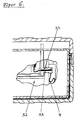
- the current conductor 4 is laid through a hinge 32 in the hinge area of this small security container in such a way that the existing predetermined breaking point 33 and thus the current conductor 4 tear under the influence of force.
- additional anchoring can be installed both in the hinge area and in the locking area, which binds the perpetrator in time.
- the alarm triggered when an attempt is made to break open can be transmitted to an auxiliary service via the state-of-the-art service of the Deutsche Bundespost "TEMEX". In this case it is possible to carry out the post-own "polling" through the current conductors 10; 4 to lock, and that to a resistance that is less than 1 kiloohm. If a current conductor 10; 4 cuts and if the "polling" (current surge) emitted by the transmitter does not arrive at the receiver, an alarm is triggered immediately.
Landscapes
- Physics & Mathematics (AREA)
- General Physics & Mathematics (AREA)
- Burglar Alarm Systems (AREA)
- Catching Or Destruction (AREA)
- Emergency Alarm Devices (AREA)
- Saccharide Compounds (AREA)
Abstract
Description
- Die Erfindung bezieht sich auf ein Wertbehälter zum Aufbewahren von Wertgegenständen nach der Gattung des Anspruchs 1.
- Derartige Wertbehälter, wie beispielsweise Tresore, Geldschränke, Münzautomaten u.s.w. sind seit Jahren bekannt und gehören zum Stand der Technik.
- Diese Wertbehälter sind immer wieder Angriffen Krimineller ausgesetzt.
- Aus diesem Grund wurden alarmgebende Außenhautsicherungen 10 in Form eng verlegter Stromleiter, wie beispielsweise in der Patentschrift DE-AS 22 02 930 angeführt, installiert, die bei physischer Einwirkung unterbrochen werden, wodurch ein Alarm ausgelöst wird.
- Diese Außenhautabsicherung deckt jedoch nur die Wandungen des Behälters ab, im Scharnier- und Schloßbereich endet sie.
- Zur Absicherung der Tür im Schloß- und Scharnierbereich werden derzeit mechanische Sensoren, wie beispielsweise Schalter, Stecker und dgl. verwendet um ein unberechtigtes öffnen zu erkennen.
- Wie jedoch die Erfahrung zeigt, werden durch diese Sensoren, beispielsweise auf Grund von Oxydation und damit verbundener schlechter Kontaktierung, häufig Fehlalarme ausgelöst, so daß der funktionale Sinn einer solchen Alarmeinrichtung mit zunehmenden Fehlalarmen in Frage gestellt ist.
- Eine Aufgabe der vorliegenden Erfindung besteht daher darin, eine technische Möglichkeit zu schaffen, den Scharnier- und Schloßbereich so abzusichern, daß im täglichen Gebrauch kein Fehlalarm ausgelöst werden kann, daß aber dennoch bei Gewalteinwirkung, bzw. unberechtigtem Öffnen ein Alarm sicher erzeugt bzw. weitergeleitet wird.
- Diese Aufgabe wird erfindungsgemäß durch die kennzeichnenden Merkmale des Anspruchs 1 gelöst.
- Beim erfindungsgemäßen Wertbehälter sind weder Kontakte, noch Schalter, Sensoren oder dgl. erforderlich, so daß eine hohe Auslösesicherheit und keine Gefahr durch Korrosion oder Alterung besteht. Da der am Verriegelungselement angeordnete Stromleiter in Reihe zum Stromleiter an den Gehäusewänden geschaltet ist, ergibt sich eine technisch einfache, kostengünstige Lösung.
- Einige Ausführungsbeispiele der Erfindung sind in den beigefügten Zeichnungen dargestellt. Es zeigen:
- Figur 1 eine beidseitige Verriegelung mit Verriegelungsgestänge, wie. z.B. beim Geldschrank oder Tresor,
- Figur 1a eine vergrößert Darstellung des Schloß- und Scharnierbereichs gemäß Figur 1,
- Figur 2 eine Verriegelungsvorrichtung für mittelgroße Wertbehälter, wie z.B. bei Münzautomaten u.s.w., in der Draufsicht,
- Figur 2a die in Figur 2 dargestellte Verriegelungsvorrichtung in der Seitenansicht,
- Figur 3 eine Hintergreifsicherung für mittelgroße Wertbehälter,
- Figur 4 eine Sicherung gegen Abreißen eines an der Wand befestigten Wertbehälter mittlerer Größe,
- Figur 5 die Verschlußeinrichtung eines kleinen Wertbehälters, wie z.B. eines Koffers, Geldbombe u.s.w. und
- Figur 6 die Scharnierabsicherung eines kleinen Wertbehälters.
- Bei dem in Figur 1 und 1a dargestellten Ausführungsbeispiel sind sowohl im Schloß- 1 als auch im Scharnierbereich 2 in der Zuhaltezone 3 Stromleiter 4 so am stabförmigen Verriegelungselement 7 verlegt, daß sie bei Gewalteinwirkung abgerissen werden und somit einen Alarm weitermelden. Diese Stromleiter sind in Reihe zu eng an der Innenseite der Gehäusewände verlegten Stromleitern 10 geschaltet. Um ein sicheres Abreißen des Stromleiters zu gewährleisten, ist im Bereich der Zuhaltung eine Sollbruchstelle 5 eingebaut. Der Stromleiter 4 ist an eine Überwachungseinrichtung angeschlossen, die nicht näher dargestellt ist.
- Damit der Täter nach dem Abbrechen der Sollbruchstelle zeitlich gebunden wird, ist ein zusätzliches als Anschlag dienendes Halteglied 6 vorgesehen, das einer Öffnungsbewegung des Verriegelungselements 7 erneut Widerstand leistet, so daß der Täter erneut zum Aufbrechen ansetzen muß.
- Diese Zuhaltung mit Sollbruchstelle, Stromleiter als Abreißsicherung und erneuter Verankerung kann verschiedenartig ausgebildet sein und kann somit den Bedürfnissen der unterschiedlichen Wertbehälter angepaßt werden.
- Bei der in den Figuren 2 und 2a dargestellten Verriegelungsvorrichtung für mittelgroße Wertbehälter greift ein Verriegelungselement 11 in der Zuhaltezone 3 zur Verriegelung eines Schloß- oder Scharnierbereichs in eine Ausnehmung eines Zuhalteteils 12 ein und liegt an einem Haltesteg 13 an. Dieser weist an beiden Seiten Sollbruchstellen 14 auf. Im Haltesteg verläuft der Stromleiter 4, der beim Ausreißen des Haltestegs 13 durchtrennt wird. Auch hier ist zur zeitlichen Bindung eines potentiellen Täters ein zusätzliches Halteglied 15 vorgesehen, das mit dem Verriegelungselement 11 verrastet.
Um zu verhindern, daß das Verriegelungselement 11 beim Verschließen vor dem Haltesteg 13 verrastet, ist ein durch das Halteglied 15 geführter Steg eingebracht. Er ist nicht mit dem Halteglied 15 verbunden und wird beim Aufbruch durch dieses hindurchgeführt. - Gemäß dem in Figur 3 dargestellten Ausführungsbeispiel für einfache Wertbehälter ist aus Kostengründen der Scharnierbereich über einen feststehenden Hintergreifhaken 17 gesichert. Beim Schließen der Behältertür wird eine Platine 18 so über den Hintergreifhaken 17 gebracht, daß dieser im geschlossenen Zustand der Tür durch eine Bohrung 20 in der Platine 18 hindurchgreift. Der auf der Platine 18 um den Hintergreifhaken 17 herum aufgebrachte Stromleiter 4 reißt bei Gewalteinwirkung auf Grund einer Sollbruchstelle 19 zwischen der Bohrung 20 und einer Seitenkante ab und meldet einen Alarm weiter.
- Ein zusätzlich angebrachtes U-förmiges Halteglied 21 umgreift den Verriegelungsbereich und bildet einen Anschlag für den losgerissenen Hintergreifhaken 17, wodurch der Täter zeitlich gebunden wird.
- Bei Wertbehältern, die fest am Mauerwerk oder dgl. verankert werden, kann aus Kostengründen auf eine Absicherung der entsprechenden Wandseite mit einer Stromleiterfläche auch verzichtet werden. Gemäß Figur 4 ist auf der Innenseite des Behälters an der entsprechenden Wandseite ein Platine 22 angebracht worden, die eine Bohrung aufweist um die herum der Stromleiter 4 gelegt ist, der als Abreißsicherung bei gewaltsamem Abreißen des Behälters dient. Durch die Bohrung wird eine Schraube 23 geführt und mit dem Mauerwerk oder dgl. fest verbunden. Bei Gewalteinwirkung zerstört der Kopf 24 der Schraube 23 die Platine 22 und damit den Stromleiter 4, so daß ein Alarm ausgelöst wird.
- An der Außenseite dieser Behälterwand kann ein nicht dargestelltes stabiles ebenfalls mit einer Bohrung versehenes Blech als erneute Verankerung angebracht werden, wobei der Durchmesser der Bohrung kleiner als der Schraubenkopf ist.
- Gemäß dem in Figur 5 dargestellten Ausführungsbeispiel kann bei kleineren Wertbehältern ein beweglicher Zuhaltebolzen 25 so eingebaut werden, daß in seiner Halterung 26 eine Sollbruchstelle 27 angebracht ist. Der Zuhaltebolzen 25 ist mit dem Stromleiter 4, so verbunden, daß dieser bei gewaltsamem Öffnen abgerissen wird und somit eine Alarmierung oder andere an sich bekannte Reaktion, wie z.B. ein Einfärben des Inhalts, erfolgt. Hierzu verläuft der Stromleiter 4 in einem hakenartigen Fortsatz 28 der Halterung 26. Der Stromleiter 4 ist bei diesem Ausführungsbeispiel unmittelbar ein Teilbereich des Stromleiters 10 an den Wänden.
- Dieser Zuhaltebolzen 25 wird zum Verschließen gemäß Figur 5 hochgestellt. In einem Verschlußteil 29 (Tür oder Deckel) befindet sich eine adäquate Aussparung in die der Zuhaltebolzen 25 gedrückt wird. Hierbei wird per Federdruck ein Schließriegel 30 in eine Aussparung 31 im Zuhaltebolzen gedrückt und somit verschlossen.
- Über der Achse 34 des Zuhaltebolzens 25 befinden sich als erneute Verankerung rechts und links des Zuhaltebolzens 25 Stege 35.
- Gemäß Figur 6 ist im Scharnierbereich dieses kleinen Wertbehälters der Stromleiter 4 so durch ein Scharnier 32 verlegt, daß bei Gewalteinwirkung die vorhandene Sollbruchstelle 33 und damit der Stromleiter 4 reißen.
- Sowohl im Scharnier- als auch im Verschlußbereich kann gemäß den vorherigen Ausführungsbeispielen eine zusätzliche Verankerung eingebaut werden, die den Täter zeitlich bindet.
- Der bei einem Aufbruchversuch ausgelöste Alarm kann über den zum Stand der Technik gehörenden Service der Deutschen Bundespost "TEMEX" zu einem Hilfsdienst übertragen werden. In diesem Fall ist es möglich, das posteigene "Polling" durch die Stromleiter 10; 4 zu schleusen, und zwar bis zu einem Widerstand der kleiner als 1 Kiloohm ist. Wird bei einem Aufbruchversuch ein Stromleiter 10; 4 durchtrennt und kommt demnach das vom Sender abgegebene "Polling" (Stromstoß) nicht am Empfänger an, wird unverzüglich Alarm ausgelöst.
Claims (2)
Applications Claiming Priority (10)
| Application Number | Priority Date | Filing Date | Title |
|---|---|---|---|
| DE19893906808 DE3906808A1 (de) | 1989-03-01 | 1989-03-01 | Sicherheitsbox |
| DE3906808 | 1989-03-01 | ||
| EP89108117 | 1989-05-05 | ||
| EP89108117 | 1989-05-05 | ||
| DE3915068 | 1989-05-09 | ||
| DE3915068A DE3915068C1 (en) | 1989-05-09 | 1989-05-09 | Safe with alarm and monitor - has narrow lead(s) broken by rod-shaped locking elements in retention region if forced open |
| DE3919269 | 1989-06-13 | ||
| DE3919269 | 1989-06-13 | ||
| DE3936084 | 1989-10-30 | ||
| DE3936084A DE3936084A1 (de) | 1989-10-30 | 1989-10-30 | Sensoren fuer die einbruchmeldeanlage |
Publications (2)
| Publication Number | Publication Date |
|---|---|
| EP0385206A1 true EP0385206A1 (de) | 1990-09-05 |
| EP0385206B1 EP0385206B1 (de) | 1993-03-17 |
Family
ID=27511274
Family Applications (1)
| Application Number | Title | Priority Date | Filing Date |
|---|---|---|---|
| EP90103085A Expired - Lifetime EP0385206B1 (de) | 1989-03-01 | 1990-02-17 | Wertbehälter |
Country Status (6)
| Country | Link |
|---|---|
| EP (1) | EP0385206B1 (de) |
| AT (1) | ATE87065T1 (de) |
| DE (1) | DE59001024D1 (de) |
| DK (1) | DK0385206T3 (de) |
| ES (1) | ES2039100T3 (de) |
| GR (1) | GR3007518T3 (de) |
Cited By (8)
| Publication number | Priority date | Publication date | Assignee | Title |
|---|---|---|---|---|
| WO1997028335A1 (de) * | 1996-02-02 | 1997-08-07 | Erich Matouschek | Alarmauslösende schliesseinrichtung für fenster oder türen |
| EP0831442A3 (de) * | 1996-09-19 | 1999-03-03 | Pax GmbH | Einbruchsicherung |
| EP0964121A1 (de) * | 1998-06-12 | 1999-12-15 | Roto Frank Ag | Zuhaltevorrichtung mit Einbruchssicherung |
| EP1130199A1 (de) * | 2000-02-16 | 2001-09-05 | Erich Matouschek | Alarmauslösendes Schliessblech mit Sollbruchplatte |
| FR2868800A1 (fr) * | 2004-04-08 | 2005-10-14 | Abcf Promotion Conseil Sarl | Dispositif de retenue d'un panneau mobile par rapport au dormant d'une ouverture |
| WO2009106195A1 (de) * | 2008-02-27 | 2009-09-03 | Wincor Nixdorf International Gmbh | Dokumentkassette |
| DE102008026598A1 (de) | 2008-06-03 | 2009-12-10 | Matouschek, Erich | Schalter zum Unterbrechen eines mit Strom beaufschlagbaren Kabels |
| EP2668355B1 (de) * | 2011-01-24 | 2017-07-12 | CareFusion 303, Inc. | Fälschungssicherer verschluss |
Families Citing this family (1)
| Publication number | Priority date | Publication date | Assignee | Title |
|---|---|---|---|---|
| US9622805B2 (en) | 2015-08-14 | 2017-04-18 | Treace Medical Concepts, Inc. | Bone positioning and preparing guide systems and methods |
Citations (3)
| Publication number | Priority date | Publication date | Assignee | Title |
|---|---|---|---|---|
| CH351859A (fr) * | 1959-01-20 | 1961-01-31 | Froidevaux Abel | Gâche |
| FR2454502A1 (fr) * | 1979-04-19 | 1980-11-14 | Pierre Ind | Protecteur de canon de serrure signalant les tentatives d'effraction |
| EP0241322A1 (de) * | 1986-03-05 | 1987-10-14 | Marc Boutroy | Sicherheitseinrichtung für den Transport von wertvollen Dokumenten |
-
1990
- 1990-02-17 AT AT90103085T patent/ATE87065T1/de not_active IP Right Cessation
- 1990-02-17 EP EP90103085A patent/EP0385206B1/de not_active Expired - Lifetime
- 1990-02-17 DK DK90103085.8T patent/DK0385206T3/da active
- 1990-02-17 DE DE9090103085T patent/DE59001024D1/de not_active Expired - Fee Related
- 1990-02-17 ES ES199090103085T patent/ES2039100T3/es not_active Expired - Lifetime
-
1993
- 1993-03-31 GR GR930400700T patent/GR3007518T3/el unknown
Patent Citations (3)
| Publication number | Priority date | Publication date | Assignee | Title |
|---|---|---|---|---|
| CH351859A (fr) * | 1959-01-20 | 1961-01-31 | Froidevaux Abel | Gâche |
| FR2454502A1 (fr) * | 1979-04-19 | 1980-11-14 | Pierre Ind | Protecteur de canon de serrure signalant les tentatives d'effraction |
| EP0241322A1 (de) * | 1986-03-05 | 1987-10-14 | Marc Boutroy | Sicherheitseinrichtung für den Transport von wertvollen Dokumenten |
Cited By (9)
| Publication number | Priority date | Publication date | Assignee | Title |
|---|---|---|---|---|
| WO1997028335A1 (de) * | 1996-02-02 | 1997-08-07 | Erich Matouschek | Alarmauslösende schliesseinrichtung für fenster oder türen |
| EP0831442A3 (de) * | 1996-09-19 | 1999-03-03 | Pax GmbH | Einbruchsicherung |
| EP0964121A1 (de) * | 1998-06-12 | 1999-12-15 | Roto Frank Ag | Zuhaltevorrichtung mit Einbruchssicherung |
| EP1130199A1 (de) * | 2000-02-16 | 2001-09-05 | Erich Matouschek | Alarmauslösendes Schliessblech mit Sollbruchplatte |
| FR2868800A1 (fr) * | 2004-04-08 | 2005-10-14 | Abcf Promotion Conseil Sarl | Dispositif de retenue d'un panneau mobile par rapport au dormant d'une ouverture |
| WO2009106195A1 (de) * | 2008-02-27 | 2009-09-03 | Wincor Nixdorf International Gmbh | Dokumentkassette |
| DE102008026598A1 (de) | 2008-06-03 | 2009-12-10 | Matouschek, Erich | Schalter zum Unterbrechen eines mit Strom beaufschlagbaren Kabels |
| EP2668355B1 (de) * | 2011-01-24 | 2017-07-12 | CareFusion 303, Inc. | Fälschungssicherer verschluss |
| EP3225768A1 (de) * | 2011-01-24 | 2017-10-04 | CareFusion 303, Inc. | Fälschungssicherer verschluss |
Also Published As
| Publication number | Publication date |
|---|---|
| DE59001024D1 (de) | 1993-04-22 |
| ES2039100T3 (es) | 1993-08-16 |
| DK0385206T3 (da) | 1993-07-12 |
| EP0385206B1 (de) | 1993-03-17 |
| ATE87065T1 (de) | 1993-04-15 |
| GR3007518T3 (de) | 1993-08-31 |
Similar Documents
| Publication | Publication Date | Title |
|---|---|---|
| CA1103047A (en) | Guarded locking device | |
| EP1037184A1 (de) | Gehäuse für einen Gefahrenmelder | |
| WO1994008632A1 (de) | Sterilisierbehälter für chirurgische instrumente oder dergleichen | |
| EP0385206B1 (de) | Wertbehälter | |
| DE4337426C2 (de) | Vorrichtung zum Verhindern des Zugangs zu einem mit einer Tür verschließbaren geschützten Sicherheitsbereich | |
| DE3936084A1 (de) | Sensoren fuer die einbruchmeldeanlage | |
| DE3204763A1 (de) | Verschlussbehaelter | |
| DE3915068C1 (en) | Safe with alarm and monitor - has narrow lead(s) broken by rod-shaped locking elements in retention region if forced open | |
| DE2749720A1 (de) | Sicherungs- und alarmvorrichtung zum absichern von tueren u.dgl. | |
| DE69808906T2 (de) | In einem raum anbringbarer detonator und ein damit versehenener sicherheitsbehälter | |
| CH668097A5 (de) | Schliessstueck oder schliesskasten zum einfraesen in - oder aufschrauben auf einen tuerstock. | |
| DE4325088A1 (de) | Wertbehälter mit Alarmeinrichtung | |
| DE3532431C2 (de) | Schlüsselschild | |
| EP0854259A1 (de) | Türschloss zur elektronischen und mechanischen Sicherung von Türen und Toren gegen Einbruch | |
| EP4093934B1 (de) | Betätigungshandhabe und vorrichtung zur einbruchsicherung | |
| EP1580363B1 (de) | Vorrichtung zur Sicherung bzw. Überwachung von Betätigungsstangen an Paniktüren oder dergleichen | |
| DE10006946C2 (de) | Alarmauslösendes Schließblech | |
| DE675988C (de) | Vorrichtung zur Sicherung von Kraftfahrzeugen gegen Diebstahl | |
| DE2708938A1 (de) | Sicherungseinrichtung | |
| DE2639050A1 (de) | Schrank fuer die aufbewahrung von wertsachen | |
| DE19505856A1 (de) | Alarmauslösende Zuhaltevorrichtung für den Schließ- und/oder Scharnierbereich einer zu sichernden Tür oder eines zu sichernden Fensters | |
| DE3209751A1 (de) | Sicherheitsschloss | |
| EP0000744A2 (de) | Panzerschrank zur Aufbewahrung von Schlüsseln | |
| DE4228398A1 (de) | Alarmmelder mit anschliessender verankerung | |
| DE102007020282A1 (de) | Meldevorrichtung mit Testmechanismus sowie Spezialschlüssel zur Betätigung des Testmechanismus |
Legal Events
| Date | Code | Title | Description |
|---|---|---|---|
| PUAI | Public reference made under article 153(3) epc to a published international application that has entered the european phase |
Free format text: ORIGINAL CODE: 0009012 |
|
| 17P | Request for examination filed |
Effective date: 19900525 |
|
| AK | Designated contracting states |
Kind code of ref document: A1 Designated state(s): AT BE CH DE DK ES FR GB GR IT LI NL SE |
|
| 17Q | First examination report despatched |
Effective date: 19910816 |
|
| GRAA | (expected) grant |
Free format text: ORIGINAL CODE: 0009210 |
|
| AK | Designated contracting states |
Kind code of ref document: B1 Designated state(s): AT BE CH DE DK ES FR GB GR IT LI NL SE |
|
| REF | Corresponds to: |
Ref document number: 87065 Country of ref document: AT Date of ref document: 19930415 Kind code of ref document: T |
|
| REF | Corresponds to: |
Ref document number: 59001024 Country of ref document: DE Date of ref document: 19930422 |
|
| GBT | Gb: translation of ep patent filed (gb section 77(6)(a)/1977) |
Effective date: 19930406 |
|
| ET | Fr: translation filed | ||
| ITF | It: translation for a ep patent filed | ||
| REG | Reference to a national code |
Ref country code: DK Ref legal event code: T3 |
|
| REG | Reference to a national code |
Ref country code: GR Ref legal event code: FG4A Free format text: 3007518 |
|
| REG | Reference to a national code |
Ref country code: ES Ref legal event code: FG2A Ref document number: 2039100 Country of ref document: ES Kind code of ref document: T3 |
|
| PLBE | No opposition filed within time limit |
Free format text: ORIGINAL CODE: 0009261 |
|
| STAA | Information on the status of an ep patent application or granted ep patent |
Free format text: STATUS: NO OPPOSITION FILED WITHIN TIME LIMIT |
|
| 26N | No opposition filed | ||
| EAL | Se: european patent in force in sweden |
Ref document number: 90103085.8 |
|
| PGFP | Annual fee paid to national office [announced via postgrant information from national office to epo] |
Ref country code: AT Payment date: 19960213 Year of fee payment: 7 |
|
| PGFP | Annual fee paid to national office [announced via postgrant information from national office to epo] |
Ref country code: GR Payment date: 19960220 Year of fee payment: 7 |
|
| PGFP | Annual fee paid to national office [announced via postgrant information from national office to epo] |
Ref country code: DK Payment date: 19960227 Year of fee payment: 7 |
|
| PGFP | Annual fee paid to national office [announced via postgrant information from national office to epo] |
Ref country code: NL Payment date: 19960229 Year of fee payment: 7 |
|
| PGFP | Annual fee paid to national office [announced via postgrant information from national office to epo] |
Ref country code: BE Payment date: 19960306 Year of fee payment: 7 |
|
| PGFP | Annual fee paid to national office [announced via postgrant information from national office to epo] |
Ref country code: CH Payment date: 19960425 Year of fee payment: 7 |
|
| PGFP | Annual fee paid to national office [announced via postgrant information from national office to epo] |
Ref country code: DE Payment date: 19970122 Year of fee payment: 8 |
|
| PGFP | Annual fee paid to national office [announced via postgrant information from national office to epo] |
Ref country code: GB Payment date: 19970123 Year of fee payment: 8 |
|
| PGFP | Annual fee paid to national office [announced via postgrant information from national office to epo] |
Ref country code: FR Payment date: 19970128 Year of fee payment: 8 |
|
| PGFP | Annual fee paid to national office [announced via postgrant information from national office to epo] |
Ref country code: ES Payment date: 19970212 Year of fee payment: 8 |
|
| PG25 | Lapsed in a contracting state [announced via postgrant information from national office to epo] |
Ref country code: DK Effective date: 19970217 Ref country code: AT Effective date: 19970217 |
|
| PGFP | Annual fee paid to national office [announced via postgrant information from national office to epo] |
Ref country code: SE Payment date: 19970217 Year of fee payment: 8 |
|
| REG | Reference to a national code |
Ref country code: DK Ref legal event code: EBP |
|
| PG25 | Lapsed in a contracting state [announced via postgrant information from national office to epo] |
Ref country code: LI Effective date: 19970228 Ref country code: CH Effective date: 19970228 Ref country code: BE Effective date: 19970228 |
|
| BERE | Be: lapsed |
Owner name: MATOUSCHEK ERICH Effective date: 19970228 Owner name: MATOUSCHEK THOMAS Effective date: 19970228 |
|
| PG25 | Lapsed in a contracting state [announced via postgrant information from national office to epo] |
Ref country code: GR Free format text: THE PATENT HAS BEEN ANNULLED BY A DECISION OF A NATIONAL AUTHORITY Effective date: 19970831 |
|
| PG25 | Lapsed in a contracting state [announced via postgrant information from national office to epo] |
Ref country code: NL Effective date: 19970901 |
|
| REG | Reference to a national code |
Ref country code: GR Ref legal event code: MM2A Free format text: 3007518 |
|
| REG | Reference to a national code |
Ref country code: CH Ref legal event code: PL |
|
| NLV4 | Nl: lapsed or anulled due to non-payment of the annual fee |
Effective date: 19970901 |
|
| PG25 | Lapsed in a contracting state [announced via postgrant information from national office to epo] |
Ref country code: GB Free format text: LAPSE BECAUSE OF NON-PAYMENT OF DUE FEES Effective date: 19980217 |
|
| PG25 | Lapsed in a contracting state [announced via postgrant information from national office to epo] |
Ref country code: SE Free format text: LAPSE BECAUSE OF NON-PAYMENT OF DUE FEES Effective date: 19980218 Ref country code: ES Free format text: LAPSE BECAUSE OF NON-PAYMENT OF DUE FEES Effective date: 19980218 |
|
| PG25 | Lapsed in a contracting state [announced via postgrant information from national office to epo] |
Ref country code: FR Free format text: THE PATENT HAS BEEN ANNULLED BY A DECISION OF A NATIONAL AUTHORITY Effective date: 19980228 |
|
| GBPC | Gb: european patent ceased through non-payment of renewal fee |
Effective date: 19980217 |
|
| EUG | Se: european patent has lapsed |
Ref document number: 90103085.8 |
|
| PG25 | Lapsed in a contracting state [announced via postgrant information from national office to epo] |
Ref country code: DE Free format text: LAPSE BECAUSE OF NON-PAYMENT OF DUE FEES Effective date: 19981103 |
|
| REG | Reference to a national code |
Ref country code: FR Ref legal event code: ST |
|
| REG | Reference to a national code |
Ref country code: ES Ref legal event code: FD2A Effective date: 20000403 |
|
| PG25 | Lapsed in a contracting state [announced via postgrant information from national office to epo] |
Ref country code: IT Free format text: LAPSE BECAUSE OF NON-PAYMENT OF DUE FEES;WARNING: LAPSES OF ITALIAN PATENTS WITH EFFECTIVE DATE BEFORE 2007 MAY HAVE OCCURRED AT ANY TIME BEFORE 2007. THE CORRECT EFFECTIVE DATE MAY BE DIFFERENT FROM THE ONE RECORDED. Effective date: 20050217 |