EP0385232A1 - Komforteinrichtung - Google Patents
Komforteinrichtung Download PDFInfo
- Publication number
- EP0385232A1 EP0385232A1 EP90103222A EP90103222A EP0385232A1 EP 0385232 A1 EP0385232 A1 EP 0385232A1 EP 90103222 A EP90103222 A EP 90103222A EP 90103222 A EP90103222 A EP 90103222A EP 0385232 A1 EP0385232 A1 EP 0385232A1
- Authority
- EP
- European Patent Office
- Prior art keywords
- snubbing
- belt
- static loop
- fulcrum
- occupant
- Prior art date
- Legal status (The legal status is an assumption and is not a legal conclusion. Google has not performed a legal analysis and makes no representation as to the accuracy of the status listed.)
- Withdrawn
Links
- 230000003068 static effect Effects 0.000 claims abstract description 43
- 238000000034 method Methods 0.000 claims abstract description 22
- 238000000605 extraction Methods 0.000 claims description 32
- 238000006073 displacement reaction Methods 0.000 claims description 14
- 230000004044 response Effects 0.000 claims description 10
- 230000008901 benefit Effects 0.000 claims description 8
- 230000036316 preload Effects 0.000 claims description 8
- 238000013459 approach Methods 0.000 claims description 5
- 230000008030 elimination Effects 0.000 claims description 3
- 238000003379 elimination reaction Methods 0.000 claims description 3
- 230000009977 dual effect Effects 0.000 claims description 2
- 101100019748 Rattus norvegicus Kcnt1 gene Proteins 0.000 description 23
- 230000007246 mechanism Effects 0.000 description 11
- 239000000284 extract Substances 0.000 description 6
- 230000007704 transition Effects 0.000 description 4
- 230000006835 compression Effects 0.000 description 3
- 238000007906 compression Methods 0.000 description 3
- 239000002184 metal Substances 0.000 description 3
- 230000004048 modification Effects 0.000 description 3
- 238000012986 modification Methods 0.000 description 3
- 230000000153 supplemental effect Effects 0.000 description 3
- 230000007257 malfunction Effects 0.000 description 2
- 238000004519 manufacturing process Methods 0.000 description 2
- 230000000717 retained effect Effects 0.000 description 2
- 230000009471 action Effects 0.000 description 1
- 238000006243 chemical reaction Methods 0.000 description 1
- 238000011161 development Methods 0.000 description 1
- 230000000694 effects Effects 0.000 description 1
- 238000010348 incorporation Methods 0.000 description 1
- 238000003780 insertion Methods 0.000 description 1
- 230000037431 insertion Effects 0.000 description 1
- 230000000750 progressive effect Effects 0.000 description 1
- 238000009877 rendering Methods 0.000 description 1
- 230000000452 restraining effect Effects 0.000 description 1
Images

Classifications
-
- B—PERFORMING OPERATIONS; TRANSPORTING
- B60—VEHICLES IN GENERAL
- B60R—VEHICLES, VEHICLE FITTINGS, OR VEHICLE PARTS, NOT OTHERWISE PROVIDED FOR
- B60R22/00—Safety belts or body harnesses in vehicles
- B60R22/18—Anchoring devices
- B60R22/19—Anchoring devices with means for reducing belt tension during use under normal conditions
Definitions
- a shoulder belt retractor includes a coiled spring actuated wind -up reel for the belt webbing which passes through a static loop mounted on the vehicle door pillar above occupants shoulder from which the belt extends across the chest of the occupant to a buckle latch at an inside anchor point.
- the comfort feature Upon reaching a sitting position with engagement of the shoulder belt retracted under wind-up belt tension, the comfort feature enables the occupant to manually extract the belt to a loosened condition upon which a latch in the retractor mechanism locks the belt against retraction.
- Such comfort feature is desirable to relieve the occupant from uncomfortable shoulder belt retraction force which often deters an occupant from using the shoulder belt with its safety advantages.
- Extraction of the shoulder belt against the retractor spool wind-up spring is normally permitted in an emergency locking retractor having an inertia responsive locking system against extraction. Accordingly, extraction can be accommodated not only to initially secure the belt buckle, as in a nonpassive manual system, but also permits the occupant to move away from the seat back, as when the driver reaches into the glove compartment or otherwise This has necessitated a sophisticated comfort feature locking mechanism which will cause release of the comfort feature locking mechanism from an overextended extraction subject to manual resetting upon return to normal sitting position.
- the method of the present invention imposes snubbing of the webbing at a position intermediate the occupant and retraction force automatically in response to a relatively light back tension imposed by mere shoulder belt contact engagement with the occupant. Further retraction by the relatively heavy retraction force is thereby arrested without preventing further retraction upon any release or loosening of the back tension imposed by such shoulder belt engagement with the occupant.
- the back tension of such method is sufficiently light to entirely eliminate discomfort to the occupant while being responsive to slack upon release to cause completion of retraction from any position of extension.
- Such method eliminates the need for functional requirements and associated mechanism in the retractor of the present "state-of-the-art" comfort lock feature, such as outlined above, and avoids the requirement for door opening or other release mechanism for the comfort feature, as well as the potential for malfunctioning upon overextension in reaching by the occupant such as described above.
- the method assures belt retraction into actual contact engagement with the occupant under all circumstances so as to eliminate any slack associated with the conventional comfort feature contributing to lost motion in the effective application of a restraining force of the shoulder belt in an emergency.
- the method provides the advantage of completely automatic operation rendering unnecessary the manual extraction of the shoulder belt to set the comfort feature
- Preferred apparatus for implementing method of the present invention includes an attachment to a conventional static loop mounted on an automotive body pillar above the occupant's shoulder which is responsive to transition in shoulder belt webbing in use by an occupant between a slack condition, incident to disconnecting the belt or to an occupant returning from belt extending position to a normal seated attitude, and a condition where all slack is taken up with webbing in contact with occupant's chest under very light unobjectionable tension.
- a pivoted lever having a fulcrum closely adjacent to the belt webbing at the top of its passage through the static loop is provided with a minimal extension for self-energized snubbing of the webbing against the static loop bar whenever the main body of the lever of substantial length is engaged by webbing projecting beyond the static loop under light tension upon elimination of slack during occupant's use.
- the fulcrum is yieldably mounted on the static loop body for displacement to a nonsnubbing position upon extraction of the belt while worn by the occupant.
- the lever is configured to hang loosely without snubbing contact in response to slack in the belt during retraction, or during extraction in a vertical direction with the fulcrum in its normal effective position.
- the lever is preferably provided with a supplemental lightly preloaded lever yieldable under minor adjustments in the occupant's chest position to provide a slight "lost motion" in the light contact pressure operation of the belt before any extraction movement of the occupant encounters the relatively heavier resistance of the main retraction spring.
- Typical spring retractors may include extended retraction forces in excess of 3 lbs. A substantial variation in spring retraction force occurs upon progressive retraction.
- the comfort feature of the present preferred method would automatically arrest retraction whenever and only when all slack is taken up with the belt engaging the occupant with insensible tension and without preventing further retraction upon any development of slack from occupant movement or disengagement of the shoulder belt. Elimination of minimum impedence is also desirable whenever slack arises so as not to delay any retraction required to take up the slack or return the belt to fully retracted condition.
- a preferred approach responsive to the transition between slack and occupant engaging condition of belt webbing, is actuated to provide snubbing with high mechanical advantage actuated by relatively light back tension whenever slack is eliminated in such transition while the belt webbing is projecting from the static loop toward occupant engagement
- conventional static loop hanger 10 swivelly attached by bolt 11 to auto body pillar 12, is equipped with a shoulder belt having vertical webbing 13 extending to a conventional spring actuated retractor, having an inertial system for locking the belt against extraction under emergency deceleration conditions arising from accident or otherwise, and having an operative webbing extension 14 for passing over the shoulder and chest of the occupant to an attachment buckle normally including a further lap engaging extension of the belt to an attachment point of the retractor.
- Retraction and extension of the belt for occupants use takes place in the vertical webbing 13 which is wound on a coiled spring actuated reel in the retractor.
- webbing 13 is normally under constant retraction tension, which may be in the order of 3 pounds or more to assure rapid retraction of the belt including the weight of the connector upon occupant's release, thereby avoiding any possibility of belt webbing hanging out of the door upon departure of the occupant.
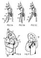
- the attachment of the present invention comprises snubbing lever 15 and fulcrum 16 attached by a pair of rivets 17 to a vertical position 18 of static loop 10 with springs 19 urging fulcrum 16 against spacing washer 20 and reaction stop 21 immediately above slot 22 for passage of belt webbing in static loop.
- the fulcrum 16a may be constructed with an extension for attachment by bolt 11a, instead of rivets 17, and made as a sheet metal element resiliently spring loaded, as by spring 19a, to its effective fulcrum position as shown in Fig. 5A.
- Such alternative will particularly facilitate attachment to a standard static loop without any modification or removal of the belt in order to accommodate "aftermarket" applications to cars which have no "comfort feature'.
- a pivotal connection between fulcrum 16 and snubbing lever 15, best illustrated in Fig. 4, includes fulcrum surface 23 immediately adjacent snubbing end 24 of lever 15 having a minimal extension beyond fulcrum surface 23 in order to maximize mechanical advantage of snubbing lever 15 from light contact pressure at lever end 24 from belt webbing 14 when worn by occupant with slack eliminated by contact with the occupant's chest.
- a supplemental comfort feature may be, and preferably is, included by employing springs 19 or 19a with sufficient preload to resist fulcrum displacement to nonsnubbing clearance until extraction tension approaches retraction tension in webbing 13, and by employing lever means which will yield from an initial lightly preloaded effective snubbing position to accommodate minor occupant shifts in position without displacing the fulcrum from its effective snubbing position; for example, a supplemental lightly preloaded sheet metal lever 33, as illustrated in Figs. 5A, 5B and 5C, with resilient means adapted to yield to permit "lost motion" in the light contact pressure snubbing operation of the belt. Such lost motion is illustrated in Fig.
- a loose but permanent connection is provided by lateral clearance slots 25 on either side of lever 15 having bevelled inner extremities 26 loosely engageable by matching bevelled ends 27 of slot engaging projections 26 loosely engageable by matching bevelled ends 27 of slot engaging projections 28 below fulcrum surface 23 which are crimped into permanent assembled relation by compression of fulcrum edges 29 accommodated by slots 30.
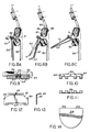
- Adequate clearance for free pivotal movement of snubbing lever 15 relative to fulcrum 16 assures desired snubbing and free snubbing release operation with spring 19 provided to position fulcrum 16 in normal snubbing attitude as shown in Figs. 3A and 3B. Such position is firmly maintained by retraction tension webbing 13 during normal snubbing action
- snubbing lever 15 preferably extends the full width of belt webbing in order to minimize wear from snubbing engagement and to match the conventional curvature in the static loop element 31 engaged by belt webbing so as to provide full snubbing contact across the width of the belt when extended in normal occupant engaging attitude.
- a preferred embodiment includes elements and functions similar to the modification of Figs. 5A, 5B, and 5C adapted to a similar static loop 40 in a manner permitting attachment, if desired, without removing pillar bolt 41 premounted in a conventional manner.
- Fulcrum 42 is formed as a sheet metal stamping with angled surfaces 43 and 44 accurately matching molded planar surfaces 45 and 46 respectively of plastic body 47. Fulcrum 42 is retained in operative position, as shown in Figs. 8A and 8B by a pair of closely wound preload springs 48 passing through upper end extremities of the loop webbing passage connected at upper center 49 and either side edge 50 of fulcrum 42 with preload tension.
- Snubbing assembly 53 comprises lever 54 hinged at 55 to a pair of snubbing elements 56 with torque spring 57 mounted on the hinge pin having loop 58 engaging lever 54 and ends 59 engaging snubbing elements 56 preloading them to a right angle hinge limit position as shown in Fig. 8A, but yieldable to a hinge opening position as shown at phantom position 60 and extraction position 61 in Figs. 8B and 8C.
- the preload of torque spring 57 is calibrated to resist any hinge opening until effective snubbing takes place, as illustrated at 62 in Fig. 8B, preventing any further retraction by retractor tension in belt webbing 50 while leveraged light occupant engaging tension prevails in belt webbing 63.
- torque spring 57 provides a low spring rate so that negligible added belt tension is felt by the occupant in actuating lever 54 from initial snubbing position 62 to hinge opening positions, such as shown at 60 and 61, so as to accommodate minor adjustments in an occupant's seating position.
- dual snubbing elements 56 are provided in order to accommodate assembly interengagement of slots 64 with fulcrum slots 65 prior to insertion of hinge pin 66.
- Respective slots 64 and 65 are dimensioned to accomodate required pivotal actuation by lever 54, as between respective positions illustrated in Figs. 8A and 8B.
- Such pivotal movement of snubbing elements 56 is limited, however, by interslot engagement to prevent complete closing of the hinged elements 54 and 56 to their 90° relationship under belt extraction such as illustrated in Fig. 8C. This provides positive assurance that snubbing elements 56 will return to effective snubbing attitude, as illustrated in Fig. 8B, upon any belt extraction followed by return of the occupant to normal seated position.
Landscapes
- Engineering & Computer Science (AREA)
- Mechanical Engineering (AREA)
- Automotive Seat Belt Assembly (AREA)
Applications Claiming Priority (4)
| Application Number | Priority Date | Filing Date | Title |
|---|---|---|---|
| US31775489A | 1989-03-02 | 1989-03-02 | |
| US317754 | 1989-03-02 | ||
| US46563790A | 1990-01-22 | 1990-01-22 | |
| US465637 | 1990-01-22 |
Publications (1)
| Publication Number | Publication Date |
|---|---|
| EP0385232A1 true EP0385232A1 (de) | 1990-09-05 |
Family
ID=26981118
Family Applications (1)
| Application Number | Title | Priority Date | Filing Date |
|---|---|---|---|
| EP90103222A Withdrawn EP0385232A1 (de) | 1989-03-02 | 1990-02-20 | Komforteinrichtung |
Country Status (2)
| Country | Link |
|---|---|
| EP (1) | EP0385232A1 (de) |
| JP (1) | JPH02270657A (de) |
Cited By (3)
| Publication number | Priority date | Publication date | Assignee | Title |
|---|---|---|---|---|
| US5286057A (en) * | 1982-09-08 | 1994-02-15 | Forster Lloyd M | Comfort feature |
| US5303953A (en) * | 1991-10-21 | 1994-04-19 | Takata Corporation | Inflatable seat belt apparatus |
| DE19950951A1 (de) * | 1999-10-22 | 2001-04-26 | Bayerische Motoren Werke Ag | Aufblasbarer Sicherheitsgurt |
Families Citing this family (1)
| Publication number | Priority date | Publication date | Assignee | Title |
|---|---|---|---|---|
| US20060170199A1 (en) * | 2005-02-02 | 2006-08-03 | Srinivasan Sundararajan | Belt guide apparatus for a seatbelt restraint system of a vehicle |
Citations (4)
| Publication number | Priority date | Publication date | Assignee | Title |
|---|---|---|---|---|
| US3981052A (en) * | 1975-07-23 | 1976-09-21 | The Firestone Tire & Rubber Company | Low friction guide loop |
| DE2813533A1 (de) * | 1978-03-29 | 1979-10-04 | Bayerische Motoren Werke Ag | Leitvorrichtung fuer eine gurtumlenkung fuer sicherheitsgurte mit gurtaufwickler in kraftfahrzeugen |
| DE3145897A1 (de) * | 1981-11-19 | 1983-05-26 | Otto 8076 Ebenhausen Glöser | Automatischer sicherheitsgurt |
| FR2612137A1 (fr) * | 1987-03-13 | 1988-09-16 | P Pac Diffusion | Dispositif de reglage de la longueur active d'une ceinture de securite |
-
1990
- 1990-02-20 EP EP90103222A patent/EP0385232A1/de not_active Withdrawn
- 1990-03-02 JP JP2049726A patent/JPH02270657A/ja active Pending
Patent Citations (4)
| Publication number | Priority date | Publication date | Assignee | Title |
|---|---|---|---|---|
| US3981052A (en) * | 1975-07-23 | 1976-09-21 | The Firestone Tire & Rubber Company | Low friction guide loop |
| DE2813533A1 (de) * | 1978-03-29 | 1979-10-04 | Bayerische Motoren Werke Ag | Leitvorrichtung fuer eine gurtumlenkung fuer sicherheitsgurte mit gurtaufwickler in kraftfahrzeugen |
| DE3145897A1 (de) * | 1981-11-19 | 1983-05-26 | Otto 8076 Ebenhausen Glöser | Automatischer sicherheitsgurt |
| FR2612137A1 (fr) * | 1987-03-13 | 1988-09-16 | P Pac Diffusion | Dispositif de reglage de la longueur active d'une ceinture de securite |
Cited By (3)
| Publication number | Priority date | Publication date | Assignee | Title |
|---|---|---|---|---|
| US5286057A (en) * | 1982-09-08 | 1994-02-15 | Forster Lloyd M | Comfort feature |
| US5303953A (en) * | 1991-10-21 | 1994-04-19 | Takata Corporation | Inflatable seat belt apparatus |
| DE19950951A1 (de) * | 1999-10-22 | 2001-04-26 | Bayerische Motoren Werke Ag | Aufblasbarer Sicherheitsgurt |
Also Published As
| Publication number | Publication date |
|---|---|
| JPH02270657A (ja) | 1990-11-05 |
Similar Documents
| Publication | Publication Date | Title |
|---|---|---|
| US5286057A (en) | Comfort feature | |
| US4239260A (en) | Adjustable emergency locking buckle anchor | |
| US5411292A (en) | Seat belt system with locking guide loop assembly | |
| US5522619A (en) | End release seat belt buckle having an inertia-sensitive locking mechanism | |
| US6701587B1 (en) | Buckle device | |
| US5188425A (en) | Pretensioning latching mechanism | |
| US4091508A (en) | Tongue plate device for use in seat belt system | |
| US4334701A (en) | Coupling for a vehicle seat belt | |
| US6902194B2 (en) | Detachable interlocking seat belt anchorage apparatus and method | |
| US4944531A (en) | Device for coupling a bracket which is provided with a buckle of a seat belt, to a retaining member, which is fixed in a vehicle | |
| US6205628B1 (en) | Buckle | |
| JP6176715B2 (ja) | バックルおよびこれを備えたシートベルト装置 | |
| US4167054A (en) | Tongue plate device for use in seat belt system | |
| US4394993A (en) | Resiliently mounted split pawl locking means for dual spool retractor | |
| US4149683A (en) | Safety belt tension eliminator with webbing sensitive release | |
| CN219989181U (zh) | 锁扣组件 | |
| US4371193A (en) | Belt anti-slip device for vehicle safety belt systems | |
| JPS5914293Y2 (ja) | シ−トベルトアンカ−装置 | |
| US4319667A (en) | Locking device for seatbelt systems | |
| CA2010419A1 (en) | Comfort feature | |
| GB2073810A (en) | Improvements in or relating to a buckle | |
| CN107351810B (zh) | 一种具有自锁功能的安全带锁舌 | |
| JPH02270657A (ja) | 快適機構 | |
| KR100221192B1 (ko) | 시트 벨트용 프리텐셔너 | |
| JPH03277301A (ja) | バックル装置 |
Legal Events
| Date | Code | Title | Description |
|---|---|---|---|
| PUAI | Public reference made under article 153(3) epc to a published international application that has entered the european phase |
Free format text: ORIGINAL CODE: 0009012 |
|
| AK | Designated contracting states |
Kind code of ref document: A1 Designated state(s): DE FR GB IT SE |
|
| 17P | Request for examination filed |
Effective date: 19901227 |
|
| 17Q | First examination report despatched |
Effective date: 19920226 |
|
| STAA | Information on the status of an ep patent application or granted ep patent |
Free format text: STATUS: THE APPLICATION IS DEEMED TO BE WITHDRAWN |
|
| 18D | Application deemed to be withdrawn |
Effective date: 19930615 |