EP0385352A2 - Von Gleichstrom gespeister Dreiphasen-Generator - Google Patents
Von Gleichstrom gespeister Dreiphasen-Generator Download PDFInfo
- Publication number
- EP0385352A2 EP0385352A2 EP90103705A EP90103705A EP0385352A2 EP 0385352 A2 EP0385352 A2 EP 0385352A2 EP 90103705 A EP90103705 A EP 90103705A EP 90103705 A EP90103705 A EP 90103705A EP 0385352 A2 EP0385352 A2 EP 0385352A2
- Authority
- EP
- European Patent Office
- Prior art keywords
- phase
- generator
- voltage
- hexfets
- outputs
- Prior art date
- Legal status (The legal status is an assumption and is not a legal conclusion. Google has not performed a legal analysis and makes no representation as to the accuracy of the status listed.)
- Withdrawn
Links
- 125000004122 cyclic group Chemical group 0.000 claims abstract description 6
- 230000008878 coupling Effects 0.000 claims description 8
- 238000010168 coupling process Methods 0.000 claims description 8
- 238000005859 coupling reaction Methods 0.000 claims description 8
- 230000003287 optical effect Effects 0.000 claims description 8
- 230000010363 phase shift Effects 0.000 claims description 3
- 239000003990 capacitor Substances 0.000 description 11
- 230000001052 transient effect Effects 0.000 description 3
- 238000010586 diagram Methods 0.000 description 2
- 238000004519 manufacturing process Methods 0.000 description 2
- 238000004804 winding Methods 0.000 description 2
- 230000004913 activation Effects 0.000 description 1
- 230000002547 anomalous effect Effects 0.000 description 1
- 230000007423 decrease Effects 0.000 description 1
- 230000003111 delayed effect Effects 0.000 description 1
- 230000007613 environmental effect Effects 0.000 description 1
- 230000000670 limiting effect Effects 0.000 description 1
- 238000013021 overheating Methods 0.000 description 1
- 230000007420 reactivation Effects 0.000 description 1
- 230000009467 reduction Effects 0.000 description 1
- 238000005057 refrigeration Methods 0.000 description 1
- 239000003381 stabilizer Substances 0.000 description 1
Images
Classifications
-
- H—ELECTRICITY
- H02—GENERATION; CONVERSION OR DISTRIBUTION OF ELECTRIC POWER
- H02M—APPARATUS FOR CONVERSION BETWEEN AC AND AC, BETWEEN AC AND DC, OR BETWEEN DC AND DC, AND FOR USE WITH MAINS OR SIMILAR POWER SUPPLY SYSTEMS; CONVERSION OF DC OR AC INPUT POWER INTO SURGE OUTPUT POWER; CONTROL OR REGULATION THEREOF
- H02M7/00—Conversion of AC power input into DC power output; Conversion of DC power input into AC power output
- H02M7/42—Conversion of DC power input into AC power output without possibility of reversal
- H02M7/44—Conversion of DC power input into AC power output without possibility of reversal by static converters
- H02M7/48—Conversion of DC power input into AC power output without possibility of reversal by static converters using discharge tubes with control electrode or semiconductor devices with control electrode
- H02M7/53—Conversion of DC power input into AC power output without possibility of reversal by static converters using discharge tubes with control electrode or semiconductor devices with control electrode using devices of a triode or transistor type requiring continuous application of a control signal
- H02M7/537—Conversion of DC power input into AC power output without possibility of reversal by static converters using discharge tubes with control electrode or semiconductor devices with control electrode using devices of a triode or transistor type requiring continuous application of a control signal using semiconductor devices only, e.g. single switched pulse inverters
- H02M7/5387—Conversion of DC power input into AC power output without possibility of reversal by static converters using discharge tubes with control electrode or semiconductor devices with control electrode using devices of a triode or transistor type requiring continuous application of a control signal using semiconductor devices only, e.g. single switched pulse inverters in a bridge configuration
- H02M7/53871—Conversion of DC power input into AC power output without possibility of reversal by static converters using discharge tubes with control electrode or semiconductor devices with control electrode using devices of a triode or transistor type requiring continuous application of a control signal using semiconductor devices only, e.g. single switched pulse inverters in a bridge configuration with automatic control of output voltage or current
- H02M7/53875—Conversion of DC power input into AC power output without possibility of reversal by static converters using discharge tubes with control electrode or semiconductor devices with control electrode using devices of a triode or transistor type requiring continuous application of a control signal using semiconductor devices only, e.g. single switched pulse inverters in a bridge configuration with automatic control of output voltage or current with analogue control of three-phase output
Definitions
- the present invention relates to a three-phase generator with direct-current supply.
- a generator of this kind is described for example in the US patent No. 4,320,449.
- the circuit is very complicated and entails excessive production costs.
- the technical aim of the invention is to provide a generator of the described type which is structurally simpler than those currently commercially available and is therefore economically advantageous for an equal performance.
- an object of the invention is to provide a three-phase generator which is reliable in operation and is particularly suitable for driving refrigeration units powered by a battery, as required in boats, campers and the like.
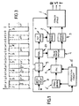
- the three-phase generator comprises a final power stage 1 feeding the three-phase voltage at the three outputs R, S, T.
- the three-phase voltage is available to the user in the form of a square wave as illustrated in figure 3.
- the final stage 1 comprises components, specified hereafter, which when controlled in a cyclic manner generate voltages with cyclically variable amplitude and polarity at the outputs R, S and T.
- the final stage is controlled by two driver modules 2 and 3 which cause the output voltage to switch to positive and to negative, respectively.
- the driver modules 2 and 3 are in turn controlled by a control stage 4 which is defined hereafter as pulse phase shifter.
- Said phase shifter is indeed capable of generating, at its outputs, pulse signals which are mutually phase shifted and which, when fed to the modules 2 and 3, control the power components of the final stage 1 so that the desired three-phase voltage is achieved at the outputs R, S and T.
- the pulses which are phase shifted in the phase shifter 4 are generated in a square-wave pulse generator 5.
- a circuit 6 which is capable of temporarily modifying the operating frequency of the generator 5.
- the reference numeral 7 indicates a stage which provides an auxiliary voltage necessary to drive the final stage 1 according to the power components used therefor, whereas 8, 9 and 10 indicate respectively a protection circuit, a high-frequency filter and a voltage stabilizer.
- the protection circuit 8 is used to protect the generator from accidental polarity reversals, from overheating and anomalous consumptions due to environmental temperatures in excess of the allowed values.
- 11 indicates a circuit adapted to protect the generator from startup instability phenomena due to supply battery voltage drops below a preset threshold value.
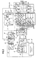
- the positive voltage of the supply battery or accumulator is connected to the input 12 of the protection circuit 8, which comprises an amperometric thermal protection device 13 with automatic reactivation, of the kind commercially known by the name KLIXON.
- a power diode 14 is coupled to said thermal protection device and short-circuits the current in case of accidental polarity reversal.
- the noise which is generated by the switchings of the components of the final power stage 1 and might interfere with radio and TV receivers is blocked in the filter 9 (which comprises, in a known manner, an inductor 15 and capacitors 16 and 17).
- the voltage at the output of the filter 9 is stabilized by an integrated circuit 18, for example the 7808 component, to the output whereof capacitors 19 are connected in order to block high-frequency and ripple residues.
- the stabilized voltage is used to supply the phase shifter 4, whereas the positive voltage of the battery is fed directly to the final power stage 1 which comprises six controllable components 20, 21, 22, 23, 24 and 25 constituted by so-called HEXFETs (e.g. IRFZ30) installed in tandem configuration.
- HEXFETs e.g. IRFZ30
- the HEXFETs 20-22 are connected in series to the respective HEXFETs 23-25, so that each pair of HEXFETs 20, 23; 21, 24; and 22, 25 is connected between the battery and the ground.
- the intermediate taps between the pairs of series-connected HEXFETs constitute the outputs R, S and T of the three-phase voltage.
- the pulse generator 5 is in practice an oscillator composed of an inverter 26, a capacitor 27 and an adjustable resistor 28 for adjusting the operating frequency.
- the generator 5 provides a square-wave pulse voltage with a frequency of 50 Hz which is fed to the phase shifter 4.
- Said phase shifter 4 is in practice constituted by an integrated circuit 29 (e.g. the 4017 component) provided with six outputs 30, 31, 32, 33, 34, 35 which has the peculiarity of dividing the input pulses so as to feed the outputs 30-35 in sequence with signals which are phase shifted by 60°.
- Each output 30-35 is connected to both driving modules 2, 3 according to a schema which determines the cyclic variation of the polarities of the voltage at the output points R, S and T.
- the module 2 is composed of three pairs of inverters which are indicated by 36, 37 and 38 and are grouped in an integrated circuit (e.g. the 40106 component).
- the inverters of each pair are mutually in cascade and are connected through a network of diodes to the outputs of the phase shifter 4. More in detail, the inverters 36 are connected, through the three-diode set 39 defining an OR circuit, to the outputs 35, 34, 33 of the phase shifter; the inverters 37 are connected, through the three-diode set 40, to the outputs 33, 32 and 31, and the inverters 38 are connected, through the three-diode set 41, to the outputs 31, 30 and 35.
- the outputs of the inverters 36, 37 and 38 are connected to the gates of the HEXFETs 20, 21 and 22 by means of respective optical coupling devices indicated by 42, 43 and 44.
- control module 3 is composed of three pairs of inverters, indicated by 45, 46 and 47, which are grouped into an integrated circuit of the 40106 type.
- the inverters of each pair are mutually in cascade and are connected, at their inputs, through three diode OR circuits 48, 49 and 50, respectively to the outputs 32, 31, 30; 30, 35, 34, and 34, 33 and 32 of the phase shifter 4.
- the inverters 45, 46 and 47 are directly connected, at their outputs, to the gates of the HEXFETs 23, 24 and 25.
- the optical coupling devices perform the task of supplying the gates of the HEXFETs with a positive auxiliary voltage which is sufficiently high with respect to the source as to allow biasing of the HEXFETs while keeping the final stage 1 de-coupled from the module 2.
- the auxiliary voltage is supplied, as described above, by the stage 7, which is substantially a voltage source composed of an oscillator 51, for example of the 1-KHz type, which drives a power transistor 52 connected in series to the primary winding of a transformer 53.
- the voltage on the secondary winding is stabilized by an integrated circuit 56, for example of the 7812 type, and filtered from noise by a capacitor 57.
- the positive terminal of the auxiliary voltage is fed to the optical coupling devices 42, 43 and 44, whereas the negative terminal is connected to the points R, S and T through three respective diodes 58, 59 and 60.
- the pulse for example at the output 30, is transmitted, through a respective diode 41 and the inverters 38, to the optical coupling device 44 and simultaneously, through respective diodes 48 and 49 and the inverters 45, 46, to the gates of the HEXFETs 23, 24.
- the pulse on the optical coupling device 44 causes the activation thereof and therefore the auxiliary positive voltage, supplied by the stage 7, is fed to the gate of the HEXFET 22 which is thus biased and switches on.
- the positive voltage of the battery thus reaches the point T.
- the voltage pulses sent to the gates of the HEXFETs 23, 24 simultaneously bias said HEXFETs, so that the points R and S are connected to the ground (negative voltage of the battery).
- the optical coupling device 44 remains activated through the diodes 41 and the inverters 38, so that the HEXFET 22 remains biased and the positive voltage remains at the point T.
- the optical coupling device 43 is activated through a diode 40 and the inverters 37 and causes the HEXFET 21 to switch on, while the gate of the HEXFET 24 is no more fed, so that the positive voltage can be supplied to the point S through the HEXFET 21.
- HEXFET 23 As regards the HEXFET 23, it should be noted that it remains biased, since the driving signal, previously fed by the output 30, is now fed by the output 31. Therefore a negative voltage ground is present at the point R.
- the circuit 6 has the task of varying the frequency of the three-phase voltage during the transient period which precedes normal operation; in the illustrated example, said circuit 6 is intended to reduce the frequency of the generator 5 and ultimately of the three-phase voltage at the output of the final stage. This frequency reduction can be used to increase startup pickup when an electric motor is connected to the three-phase voltage.
- the circuit 6 comprises a capacitor 61 which has one terminal connected to the positive terminal of the battery and the opposite terminal connected to the base of a transistor 63 through a pair of inverters 62.
- a capacitor 64 is connected to the emitter terminal of the transistor 63 and is connected to the input of the inverter 26 of the generator 5.
- the transistor 63 starts conducting, so that the capacitor 64 is connected in parallel to the capacitor 27, lowering the frequency of the generator 5.
- the base to emitter voltage of the transistor 63 decreases until it switches off, disconnecting the capacitor 64 and therefore restoring the normal operating frequency of the generator 5.
Landscapes
- Engineering & Computer Science (AREA)
- Power Engineering (AREA)
- Inverter Devices (AREA)
- Ac-Ac Conversion (AREA)
- Control Of Eletrric Generators (AREA)
Applications Claiming Priority (2)
| Application Number | Priority Date | Filing Date | Title |
|---|---|---|---|
| IT8903367A IT1234425B (it) | 1989-03-03 | 1989-03-03 | Generatore trifase alimentato in corrente continua |
| IT336789 | 1989-03-03 |
Publications (2)
| Publication Number | Publication Date |
|---|---|
| EP0385352A2 true EP0385352A2 (de) | 1990-09-05 |
| EP0385352A3 EP0385352A3 (de) | 1990-12-12 |
Family
ID=11105801
Family Applications (1)
| Application Number | Title | Priority Date | Filing Date |
|---|---|---|---|
| EP19900103705 Withdrawn EP0385352A3 (de) | 1989-03-03 | 1990-02-26 | Von Gleichstrom gespeister Dreiphasen-Generator |
Country Status (4)
| Country | Link |
|---|---|
| EP (1) | EP0385352A3 (de) |
| AU (1) | AU5070390A (de) |
| CA (1) | CA2011138A1 (de) |
| IT (1) | IT1234425B (de) |
Cited By (2)
| Publication number | Priority date | Publication date | Assignee | Title |
|---|---|---|---|---|
| EP0528102A3 (en) * | 1991-08-20 | 1993-06-16 | Tecumseh Products Company | Protection circuit in inverter for refrigerators |
| WO1993021684A1 (en) * | 1992-04-09 | 1993-10-28 | Luigi Lavazza S.P.A. | A circuit for controlling a vibration pump, for example for drink dispensing machines |
Family Cites Families (2)
| Publication number | Priority date | Publication date | Assignee | Title |
|---|---|---|---|---|
| US4126819A (en) * | 1977-07-01 | 1978-11-21 | Kearney & Trecker Corporation | Interlock circuit for complementary electronic switches |
| JPS5928151B2 (ja) * | 1978-11-04 | 1984-07-11 | ファナック株式会社 | 電動機駆動用インバ−タ回路の保護方式 |
-
1989
- 1989-03-03 IT IT8903367A patent/IT1234425B/it active
-
1990
- 1990-02-26 EP EP19900103705 patent/EP0385352A3/de not_active Withdrawn
- 1990-02-28 CA CA002011138A patent/CA2011138A1/en not_active Abandoned
- 1990-03-02 AU AU50703/90A patent/AU5070390A/en not_active Abandoned
Cited By (2)
| Publication number | Priority date | Publication date | Assignee | Title |
|---|---|---|---|---|
| EP0528102A3 (en) * | 1991-08-20 | 1993-06-16 | Tecumseh Products Company | Protection circuit in inverter for refrigerators |
| WO1993021684A1 (en) * | 1992-04-09 | 1993-10-28 | Luigi Lavazza S.P.A. | A circuit for controlling a vibration pump, for example for drink dispensing machines |
Also Published As
| Publication number | Publication date |
|---|---|
| EP0385352A3 (de) | 1990-12-12 |
| AU5070390A (en) | 1990-09-06 |
| IT1234425B (it) | 1992-05-18 |
| CA2011138A1 (en) | 1990-09-03 |
| IT8903367A0 (it) | 1989-03-03 |
Similar Documents
| Publication | Publication Date | Title |
|---|---|---|
| US5914590A (en) | Electrical power regulator | |
| US7403401B2 (en) | DC-AC converter and method of supplying AC power | |
| US4742441A (en) | High frequency switching power converter | |
| US7920390B2 (en) | DC-AC converter, controller IC therefor, and electronic apparatus utilizing such DC-AC converter | |
| US5253157A (en) | Half-bridge inverter with capacitive voltage equalizer | |
| US7095635B2 (en) | Dc/ac converter and controller IC | |
| US7599204B2 (en) | Control scheme providing a freewheeling period in a cyclo-converter and a high frequency inverter | |
| US4970620A (en) | FET bridge protection circuit | |
| JPH03503592A (ja) | フィードフォワード及びフィードバックの制御機能を備えたdc/dcコンバータ | |
| US4719558A (en) | High-frequency power supply output control device | |
| US4086526A (en) | Method of and a power switching device for regulating the electrical power delivered to a consumer in an A.C. network | |
| US5245272A (en) | Electronic control for series circuits | |
| US4811185A (en) | DC to DC power converter | |
| US7015679B2 (en) | Circuit and method for supplying an electrical a.c. load | |
| EP0622890B1 (de) | Schaltnetzteilsystem für ferngesteuerte Fernsehempfänger oder dergleichen | |
| US6414448B1 (en) | Electronic ballast for a gas discharge lamp | |
| EP0385352A2 (de) | Von Gleichstrom gespeister Dreiphasen-Generator | |
| JP3025715B2 (ja) | インバータ回路 | |
| US5017802A (en) | Base current regulation circuit for a switching transistor, in particular a bipolar transistor | |
| US4908752A (en) | DC-to-DC voltage-increasing power source | |
| US5334914A (en) | Vehicle instrument panel lamps, pulse width dimmer system therefor | |
| US5517402A (en) | Inverter circuit with an improved inverter driving circuit | |
| US6801063B1 (en) | Charge compensated bootstrap driving circuit | |
| US4247887A (en) | AC--AC Converter device | |
| US5682302A (en) | Adaptable power converter applying digitized-wave-generation for integrated circuit implementation |
Legal Events
| Date | Code | Title | Description |
|---|---|---|---|
| PUAI | Public reference made under article 153(3) epc to a published international application that has entered the european phase |
Free format text: ORIGINAL CODE: 0009012 |
|
| AK | Designated contracting states |
Kind code of ref document: A2 Designated state(s): DE ES FR GB SE |
|
| PUAL | Search report despatched |
Free format text: ORIGINAL CODE: 0009013 |
|
| AK | Designated contracting states |
Kind code of ref document: A3 Designated state(s): DE ES FR GB SE |
|
| STAA | Information on the status of an ep patent application or granted ep patent |
Free format text: STATUS: THE APPLICATION IS DEEMED TO BE WITHDRAWN |
|
| 18D | Application deemed to be withdrawn |
Effective date: 19910613 |