EP0385382A2 - Procédé et appareillage pour le traitement thermique de matériaux semi-conducteurs - Google Patents
Procédé et appareillage pour le traitement thermique de matériaux semi-conducteurs Download PDFInfo
- Publication number
- EP0385382A2 EP0385382A2 EP90103766A EP90103766A EP0385382A2 EP 0385382 A2 EP0385382 A2 EP 0385382A2 EP 90103766 A EP90103766 A EP 90103766A EP 90103766 A EP90103766 A EP 90103766A EP 0385382 A2 EP0385382 A2 EP 0385382A2
- Authority
- EP
- European Patent Office
- Prior art keywords
- gases
- space
- tube
- reaction
- semiconductor wafers
- Prior art date
- Legal status (The legal status is an assumption and is not a legal conclusion. Google has not performed a legal analysis and makes no representation as to the accuracy of the status listed.)
- Withdrawn
Links
Images


Classifications
-
- H—ELECTRICITY
- H10—SEMICONDUCTOR DEVICES; ELECTRIC SOLID-STATE DEVICES NOT OTHERWISE PROVIDED FOR
- H10P—GENERIC PROCESSES OR APPARATUS FOR THE MANUFACTURE OR TREATMENT OF DEVICES COVERED BY CLASS H10
- H10P72/00—Handling or holding of wafers, substrates or devices during manufacture or treatment thereof
- H10P72/04—Apparatus for manufacture or treatment
- H10P72/0431—Apparatus for thermal treatment
- H10P72/0436—Apparatus for thermal treatment mainly by radiation
-
- C—CHEMISTRY; METALLURGY
- C30—CRYSTAL GROWTH
- C30B—SINGLE-CRYSTAL GROWTH; UNIDIRECTIONAL SOLIDIFICATION OF EUTECTIC MATERIAL OR UNIDIRECTIONAL DEMIXING OF EUTECTOID MATERIAL; REFINING BY ZONE-MELTING OF MATERIAL; PRODUCTION OF A HOMOGENEOUS POLYCRYSTALLINE MATERIAL WITH DEFINED STRUCTURE; SINGLE CRYSTALS OR HOMOGENEOUS POLYCRYSTALLINE MATERIAL WITH DEFINED STRUCTURE; AFTER-TREATMENT OF SINGLE CRYSTALS OR A HOMOGENEOUS POLYCRYSTALLINE MATERIAL WITH DEFINED STRUCTURE; APPARATUS THEREFOR
- C30B31/00—Diffusion or doping processes for single crystals or homogeneous polycrystalline material with defined structure; Apparatus therefor
- C30B31/06—Diffusion or doping processes for single crystals or homogeneous polycrystalline material with defined structure; Apparatus therefor by contacting with diffusion material in the gaseous state
- C30B31/12—Heating of the reaction chamber
-
- C—CHEMISTRY; METALLURGY
- C30—CRYSTAL GROWTH
- C30B—SINGLE-CRYSTAL GROWTH; UNIDIRECTIONAL SOLIDIFICATION OF EUTECTIC MATERIAL OR UNIDIRECTIONAL DEMIXING OF EUTECTOID MATERIAL; REFINING BY ZONE-MELTING OF MATERIAL; PRODUCTION OF A HOMOGENEOUS POLYCRYSTALLINE MATERIAL WITH DEFINED STRUCTURE; SINGLE CRYSTALS OR HOMOGENEOUS POLYCRYSTALLINE MATERIAL WITH DEFINED STRUCTURE; AFTER-TREATMENT OF SINGLE CRYSTALS OR A HOMOGENEOUS POLYCRYSTALLINE MATERIAL WITH DEFINED STRUCTURE; APPARATUS THEREFOR
- C30B31/00—Diffusion or doping processes for single crystals or homogeneous polycrystalline material with defined structure; Apparatus therefor
- C30B31/06—Diffusion or doping processes for single crystals or homogeneous polycrystalline material with defined structure; Apparatus therefor by contacting with diffusion material in the gaseous state
- C30B31/16—Feed and outlet means for the gases; Modifying the flow of the gases
Definitions
- the invention relates to a method for the thermal treatment of half-age materials in which the semiconductor wafers to be treated or the like.Process gas mixtures of different and changing composition and temperature are exposed and a device for carrying out the method, which has a vertically arranged process space with a process tube open on one side and a Cylindrical heating cassette comprising the process tube in which the semiconductor wafers to be treated are arranged on a carrier and a fluid flushing provided in an annular space comprising the process tube.
- Devices for carrying out such processes are also generally known under the term “diffusion furnace”. They essentially consist of a process tube surrounded by a heating cassette and the loading device, usually a so-called. Cantilever system. Such diffusion furnaces are mostly used as horizontal furnaces, ie the process tube is arranged hortizontally and is loaded with the semiconductor wafers to be treated from the front. Vertical ovens are also known in which the process tube is arranged vertically and which are loaded with the semiconductor wafers from below or from above. The known vertical furnaces consist essentially of the vertically arranged process tube, which is enclosed by a heating cassette of conventional design.
- the semiconductor wafers are stacked vertically one above the other in the process tube in a hanging or standing horde at process-related intervals, but aligned horizontally. They are subjected to heat treatment in the process tube with different process gases that flow through the reaction chamber from bottom to top. At its open end, below or above, the reaction chamber is largely sealed against the surrounding clean room atmosphere by means of loosely placed closure elements with integrated gas supply and discharge lines. Gas displacement purging is used to carry out the method which is adapted to the device.
- the invention seeks to remedy this.
- the Erfin dung as characterized in the claims, solves the problem of avoiding the disadvantages described above with certainty and to have a method and an apparatus for performing the method, which is adapted to the method and in which the gas flow within the reaction space can be controlled is.
- the yield is not only improved, but the process conditions and thus the reproducibility thereof are given.
- the gas streams are no longer always directed to the same location of the semiconductor wafers to be treated as before, but rather they hit the surface of the semiconductor wafers at ever changing angles.
- the oblique position of the semiconductor discs on the tray ensures that no undesired gas concentrations form on certain parts of the surface thereof.
- Another advantage is the higher direction of flow of the gas flows from top to bottom, ie the gas is removed from the bottom of the process space and cannot collect at the top or at other points.
- the use of inert purge gases to prevent any contamination from the area of the heating cassette is a further advantage. This means that no molecular or atomic impurities can get into the reaction space.
- the effective cooling by purging gases in the jacket and intermediate space contributes to rapid batch changes and thus to an economical implementation of the process.
- the necessary The device is adapted to the process conditions and, in addition to a multi-tube system consisting of an inner and an outer reaction tube, in particular a rotating table for the semiconductor wafers to be treated during the course of the method, has swirling nozzles provided on the wall of the inner process tube for introducing the process gases into the process space .
- the system design also has the advantage, especially for the implementation of heat treatment processes for a few or only a single semiconductor wafer, even very large ones (single-wafer processes or cassette-to-cassette single-wafer process) to be suitable.
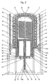
- the device shown in Figure 1 is the main component of a so-called. Diffusion furnace, namely the actual process unit, which essentially consists of the inner process tube 1, the outer process tube 2, which are preferably made of quartz, the jacket tube 3, for example made of ceramic, the heating cassette 4 with the further heating elements 17 and 18 and the reaction chamber closure system 15 and the rotary table 14.
- the actual process unit which essentially consists of the inner process tube 1, the outer process tube 2, which are preferably made of quartz, the jacket tube 3, for example made of ceramic, the heating cassette 4 with the further heating elements 17 and 18 and the reaction chamber closure system 15 and the rotary table 14.
- the approximately bell-shaped heating cassette 4 is still surrounded by the hood 6 on the outside.
- This hood 6 has at its upper end an opening for the purge gas outlet connection 24 and the cooling gas outlet connection 25 of the heating cassette jacket cooling unit 5.
- the process gas is introduced into the inner isothermal reaction space 8 through at least one row of holes 7 in such a way that the process gas flows around the semiconductor wafers 11 located on the turntable 14, ie its disk carrier 13 with its disk receptacles 12.
- the row of holes-n 7 is / are therefore preferably provided in the form of a screw with a different pitch and an indefinite number of holes in the wall of the inner reaction tube 1, the diameter of the holes being approximately 0.5 mm or larger and the spatial axis of the holes relative to the central tube axis is disoriented.
- the semiconductor wafers 11 are layered on top of one another on the wafer holder 12 in a slightly inclined arrangement, so that during the treatment the entire surface thereof is exposed to the gas stream from the or the rows of holes 7.
- a batch consists of a typical lot size of 25 semiconductor wafers 11 plus a few dummies. With non-critical processes, more semiconductor wafers can be retracted and treated at the same time the.
- the process gas mixture is introduced into the process gas intermediate space 9 through the inlet connection 28 and removed again from the system through the process gas outlet pipe 30.
- an outer annular washing chamber 10 is provided, which in so-called.
- "Low-flow mode” or “high-flow mode” is flushed with purge gas, on the one hand in “low-flow mode” with a few liters of purge gas per minute to prevent the reaction chamber from being contaminated by components of the heating cassette 4 and on the other hand, rapid cooling can be achieved in "high-flow mode”.
- the entire system is quickly cooled to temperatures well below the usual stand-by temperatures of 700 ° to 800 ° C. This means that stand-by temperatures of 300 ° C and below (up to room temperature) can be achieved, i.e. the so-called "Fast heating cassette” is thus realized.
- the hood 6 serving as a heating cassette casing is designed to be suitable for clean rooms, which is why Stainless steel works well.
- a process gas preheater 16 which is designed as a cylindrical, double-walled ring with a wide flange and carries the reaction tube 1.
- the heating element 17, arranged below the reaction tube 1 in the reaction space closure system 15, is carried by a support ring 21.
- the process gas preheater 16 contains a cylindrical heating element 18 and has one or more process gas inlet channels 28 in its flange-shaped collar.
- the support tube 21 is on the support tube bearing shell 22 with integrated cooling made of heat-resistant, lubricant-free material, such as Ceramic arranged, the air cooling cools the bearing 35 made of ceramic or metal or plastic. With 26 a flange connection is designated.
- the entire system 1 to 28 is carried by a common mounting device 29, to which a water cooling duct 31 and air cooling duct 32 are also flanged.
- the coaxial support tube 33 of the turntable 14 is provided on the inside with an air cooling tube 33a.
- This support tube 33 is mounted in the bearings 34 and 35.
- Inert gas flushing is provided in the protective tube 36 and has a suction device with a multi-way valve.
- the drive 37 of the turntable 14 is arranged in the frame 40, which carries the system which can be moved into the reaction tube unit from below, and in bearings 39 on the Rail system 38 is guided.
- the rail system 38 is attached to the frame 41.
- The, cylindrically designed, closure system of the reaction space, designated 15, has a multiple function. First of all, it serves to seal the reaction chamber 8 in a vacuum-tight manner on the loading side, that is to say from below. It carries the adjustable heating element 17, which is necessary to maintain the isothermal energy and is fixed in the position shown by the support ring 21.
- the closure system 15 preferably consists of a material suitable for semiconductors, for example quartz, polysilicon, SiC or other ceramic materials, all of which have to be dimensionally stable up to well over 1300 ° C.
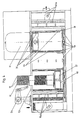
- FIG. 2 While acc. FIG. 1 of the turntable 14 together with the closure system of the reaction space 8 after loading with semiconductor wafers 11 is inserted into the stationary reaction tube 1 from below, the embodiment variant shown in FIG. 2 provides that the complete reaction unit, consisting of the inner reaction tube 1 , the outer reaction tube 2, the jacket tube 3, the heating cassette 4 with the hood 6 and the supply and discharge lines 27 for the purge gas and the jacket cooling 5 is moved upwards, while the turntable 14 remains stationary.
- the closure system of the reaction space 15 is again held in the frame 40 and the frame 41 for the rail system 44 is arranged laterally.
- a holding plate 42 with two ring flanges carries the movable reaction unit and slides over the slide bearings 39 on the bars of the rail system 44.
- the upper ring flange and 43b the lower ring flange are designated.
- An inner, adjustable heating cylinder 45 is below of the turntable 14 provided.
- the preheating of the process gases acc. 2 is ensured by the arrangement of the heating elements 45 and 46 and the process gas inlets and outlets 28 and 30 provided in the closure system 15 of the reaction chamber 8.
- the end plate of the pipe closure system is designated 47. This carries the controllable heating elements 17, 45 and 46, arranged in such a way that the process gases flowing in from below are preheated and condensation of the exhaust gases flowing downward is prevented in the overall system.
- Remaining cavities are filled with quartz wool inside the jacket 48 to ensure the necessary thermal insulation.
- an annular seal 49 with fluid cooling is provided.
- FIG. 3 shows another design of the process gas preheater 16 according to FIG. Figure 1, or 17, 45 and 46 acc. Figure 2.
- the process gas preheater acc. Figure 3 consists of the cylindrical heating element 50 and a U-shaped ring flange 51, which can optionally also be composed of individual segments and a heating element 52.
- This heating element 52 can be formed from individual, rod-shaped, ring-forming individual heating elements as well also from a heating coil which is wound around the U-shaped flange 51, or from individual insertable heating element segments which are adapted to the U-shaped ring flange 51.
- Such an arrangement of the heating elements 50 and 52 enables rapid replacement and easier adaptation to different process parameters.
- Figure 4 shows the side view of a diffusion fens with vertical, stationary reaction unit and turntable 14 that can be moved downwards.
- a robot 54 On a clean room table 53, outside the actual reaction unit, as in Fl g. 1, a robot 54 is mounted, which automatically loads and unloads the turntable 14. To this end, the turntable 14 is loaded — on the top left in the image — with semiconductor wafers 11 and, after being lowered by means of the displacement device 56, is moved to the right in order to move into the reaction tube 1 to the right and upwards.
- 55a and 55b designate blowers, including filter units, to ensure that during the up and down and translational movements in the tunnel under the clean room table 53, the panes are moved exclusively in clean room air of class 1-5.
- Figure 5 shows a diffusion furnace acc. Figure 2 with stationary turntable 14 and upwardly movable reaction unit.
- the reaction unit is raised so that the robot 54 can insert the semiconductor wafers 11 into the turntable 14 or remove them therefrom.
- reaction tube 1 oxygen, H-tempering, diffusion, deposition
- Example 1 Oxidation (explained using FIG. 4)
- the inner isothermal reaction chamber 8 is tempered to start temperatures between room temperature and 300 ° C. and the turntable 14 is loaded with semiconductor wafers 11 by the robot 54 removing these wafers from a storage tray (not shown) and inserting them into disk receptacles 12 of the disk carrier 13.
- the disc receptacles 12 are preferably round and are shaped up to well above 1300 ° C. stable. Slipping of the inclined discs 11 is avoided by a stop in the disc holder.
- the turntable 14 then moves downward and then to the left in order to then move upward again into the reaction space 8 of the reaction unit, as can be seen from FIGS. 1 and 4.
- the turntable 14 remains stationary, for this purpose the reaction unit with the reaction space 8 is raised, so that the loading process can be carried out by the robot. After the loading is complete, the reaction unit is lowered again.
- a gas exchange is first carried out, the initially largely atmospheric composition of the gases in the reaction space 8 being exchanged for the process gas mixture which has already been heated by the process gas preheater 16 by means of a “soft pump-down” step , ie by single or multiple evacuation and refilling with the desired process gas mixture.
- the exchange of the gases takes place through the process gas inlet connector 28 and the process gas outlet tube 30.
- the pressure in the inner reaction tube 8 is adjusted to the required values depending on the process.
- the variants according to 4. are particularly suitable for the generation of low-power gate oxide layers of approximately 2-10 nM (20 - 100 A) with the best possible reproducibility and the smallest process tolerances.
- the oxidation is ended by repeating the process gases through N using a further "soft pump-down” step. This is followed by a linear ramping-down to approx. 800 C and dwelling at this temperature for different lengths of time.
- the purge gas inlet nozzle 27 and the outlet nozzle 24 from "low” Flow mode "switched to" high flow mode using N2 in order to quickly cool the entire system to about 300 ° C, or, depending on the process, to room temperature.
- the turntable 14 rotates slowly during the entire process, with possibly changing angular velocities, with the semiconductor wafers 11 in the radial gas flow which is distributed between the semiconductor wafers and thus rinses their entire surface. In this way, an extremely uniform, reproducible process result is achieved.
- the turntable 14 is preferably made of polysilicon, ceramic or other semiconductor-compatible materials, such as e.g. SiC or others and is dimensionally stable up to well over 1300 C, designed as a disc, which has a downwardly projecting coaxial support tube 33 made of the same material with double bearings 34, 35 with inner 33 a and outer 22 cooling.
- the turntable 14 is first loaded as described in Example 1.
- the annealing of semiconductor wafers in the device which represents an absolutely closed, vertically arranged furnace system, has clearly defined gas inlet and gas outlet openings and enables both the start and the end of the process carried out therein at room temperature, in 100% pure hydrogen in the cold -Hot-cold cycle performed.
- the advantages of the device according to the invention advantageously involve process control with secured gas exchange (initially undefined clean room air is exchanged for N2 and then the nitrogen for pure H2 100%) at room temperature, ramping up to the desired tempering temperature (typically: 420 ° - 490 ° C or higher), process-dependent residence at this temperature and then defined cooling in the 100% H2 atmosphere down to room temperature and then - still in the closed system - exchange this 100% H2 for N2 and then, after an appropriate purging time with purging gas, replace it with the clean room atmosphere for discharging as in Example 1
- Example 3 Diffusion, covering with dopant.
- a further advantage of the device according to the invention is, for the first time in connection with the "soft pump-down" step at an arbitrarily predeterminable point in time during the method, the clearly defined immediate termination of a dopant coating, ie the immediate termination of the dopant feed into the reaction space 8 and spontaneous suction of this doping gas mixture from the reaction chamber 8. This means that even very low doping with minimal penetration depths xj and high sheet resistance values R S ⁇ / 0, ie lowest surface concentrations, can be achieved.
- the device designed according to the invention achieves a significantly better process quality and reproducibility.
- This also contributes to the formation of the inner process tube 1, the so-called.
- Injector tube is formed, because by this measure the entire system from the outset to the so-called.
- "in-cage” process control is coordinated, ie for all processes of oxidation, tempering, dif fusion / occupancy, drive-in, deposition etc.
- Disc carriers are incorporated or placed in these in closed cylinders with terminal plates and several rows of holes in the cylinder surface (for the process gas inlet).
- the disadvantages associated with this "cage-boats" technology in the process control namely the fixed position of the semiconductor wafers relative to the holes in the rows of holes and the consequent system-related uneven flow is excluded in the device proposed according to the invention.
- the semiconductor wafers 11 and the rows of holes 7 are namely arranged obliquely to one another, the semiconductor wafers being in a rotational movement on the turntable 14 relative to them and thus also relative to the injection current.
Landscapes
- Chemical & Material Sciences (AREA)
- Engineering & Computer Science (AREA)
- Crystallography & Structural Chemistry (AREA)
- Materials Engineering (AREA)
- Metallurgy (AREA)
- Organic Chemistry (AREA)
Applications Claiming Priority (2)
| Application Number | Priority Date | Filing Date | Title |
|---|---|---|---|
| DE3906075A DE3906075A1 (de) | 1989-02-27 | 1989-02-27 | Verfahren zur thermischen behandlung von halbleitermaterialien und vorrichtung zur durchfuehrung desselben |
| DE3906075 | 1989-02-27 |
Publications (2)
| Publication Number | Publication Date |
|---|---|
| EP0385382A2 true EP0385382A2 (fr) | 1990-09-05 |
| EP0385382A3 EP0385382A3 (fr) | 1991-08-28 |
Family
ID=6375030
Family Applications (1)
| Application Number | Title | Priority Date | Filing Date |
|---|---|---|---|
| EP19900103766 Withdrawn EP0385382A3 (fr) | 1989-02-27 | 1990-02-27 | Procédé et appareillage pour le traitement thermique de matériaux semi-conducteurs |
Country Status (3)
| Country | Link |
|---|---|
| EP (1) | EP0385382A3 (fr) |
| JP (1) | JPH03200326A (fr) |
| DE (1) | DE3906075A1 (fr) |
Cited By (7)
| Publication number | Priority date | Publication date | Assignee | Title |
|---|---|---|---|---|
| EP0507387A1 (fr) * | 1991-04-05 | 1992-10-07 | STMicroelectronics S.r.l. | Dispositif de chauffe pour cuves chimiques |
| US5318632A (en) * | 1992-05-25 | 1994-06-07 | Kawasaki Steel Corporation | Wafer process tube apparatus and method for vertical furnaces |
| EP0735575A1 (fr) * | 1995-03-31 | 1996-10-02 | Asm International N.V. | Four vertical |
| EP1345255A3 (fr) * | 2002-03-15 | 2005-09-07 | Asm International N.V. | Socle à niveaux multiples pour un four |
| EP1522090A4 (fr) * | 2002-07-15 | 2006-04-05 | Aviza Tech Inc | Systeme de traitement thermique et chambre verticale configurable |
| CN108981391A (zh) * | 2018-09-06 | 2018-12-11 | 洛阳智多鑫机械科技有限公司 | 一种带转盘的箱式电窑炉 |
| CN118422351A (zh) * | 2024-07-04 | 2024-08-02 | 博海新能源(合肥)有限公司 | 一种太阳电池制造用扩散炉喷淋进气管 |
Families Citing this family (5)
| Publication number | Priority date | Publication date | Assignee | Title |
|---|---|---|---|---|
| DE3922833A1 (de) * | 1989-07-09 | 1991-01-10 | Heinrich Dr Soehlbrand | Ofen zur waermebehandlung von halbleiterscheiben und verfahren zum betrieb desselben |
| DE9106825U1 (de) * | 1991-06-04 | 1992-10-01 | Ipsen Industries International Gmbh, 4190 Kleve | Wärmebehandlungsofen |
| JP3230836B2 (ja) * | 1992-04-09 | 2001-11-19 | 東京エレクトロン株式会社 | 熱処理装置 |
| JPH088194A (ja) * | 1994-06-16 | 1996-01-12 | Kishimoto Sangyo Kk | 気相成長機構および熱処理機構における加熱装置 |
| JP3971810B2 (ja) * | 1995-11-30 | 2007-09-05 | 三星電子株式会社 | 縦型拡散炉 |
Family Cites Families (14)
| Publication number | Priority date | Publication date | Assignee | Title |
|---|---|---|---|---|
| DE8302957U1 (de) * | 1983-08-04 | Helmut Seier GmbH, 7760 Radolfszell | Vorrichtung zur Hitzebehandlung von Halbleitersubstraten und dergleichen | |
| DE2610556C2 (de) * | 1976-03-12 | 1978-02-02 | Siemens AG, 1000 Berlin und 8000 München | Vorrichtung zum Verteilen strömender Medien über einen Strömungsquerschnitt |
| DE2642813A1 (de) * | 1976-09-23 | 1978-03-30 | Siemens Ag | Anordnung zum eindiffundieren von dotierstoffen |
| DE3028003C1 (de) * | 1980-07-24 | 1981-10-08 | Basf Ag, 6700 Ludwigshafen | Vorrichtung zur Verteilung eines aus einem Rohr ankommenden Gases auf den Querschnitt eines Behaelters |
| DE3142589A1 (de) * | 1981-10-27 | 1983-05-05 | Siemens AG, 1000 Berlin und 8000 München | Verfahren zum tempern von aus metall, silizium und aus metall/silizium bestehenden schichten auf substraten in extrem trockener inertgasatmosphaere |
| JPS6081093A (ja) * | 1983-10-06 | 1985-05-09 | Ulvac Corp | 気相エピタキシヤル成長用化学反応装置 |
| US4695706A (en) * | 1983-12-28 | 1987-09-22 | Denkoh Co. Ltd. | Vertical furnace for heat-treating semiconductor |
| JPS60152675A (ja) * | 1984-01-20 | 1985-08-10 | Toshiba Mach Co Ltd | 縦型拡散炉型気相成長装置 |
| DE3441887C1 (de) * | 1984-11-16 | 1985-10-17 | Heraeus Quarzschmelze Gmbh, 6450 Hanau | Ofen fuer die Waermebehandlung von Halbleiter-Substraten |
| DD235305A1 (de) * | 1985-03-07 | 1986-04-30 | Halle Ingenieurtech | Vorrichtung zur verteilung fluider medien mittels stroemungsbeeinflussung |
| JPS6252200A (ja) * | 1985-08-28 | 1987-03-06 | Nec Corp | 気相エピタキシヤル成長装置 |
| DE3544812A1 (de) * | 1985-12-18 | 1987-06-25 | Heraeus Schott Quarzschmelze | Doppelwand-quarzglasrohr fuer die durchfuehrung halbleitertechnologischer prozesse |
| US4926793A (en) * | 1986-12-15 | 1990-05-22 | Shin-Etsu Handotai Co., Ltd. | Method of forming thin film and apparatus therefor |
| DE3702734C1 (en) * | 1987-01-30 | 1987-10-29 | Heraeus Schott Quarzschmelze | Oven with a diffusion tube for treating semiconductor wafers |
-
1989
- 1989-02-27 DE DE3906075A patent/DE3906075A1/de active Granted
-
1990
- 1990-02-27 JP JP2044679A patent/JPH03200326A/ja active Pending
- 1990-02-27 EP EP19900103766 patent/EP0385382A3/fr not_active Withdrawn
Cited By (8)
| Publication number | Priority date | Publication date | Assignee | Title |
|---|---|---|---|---|
| EP0507387A1 (fr) * | 1991-04-05 | 1992-10-07 | STMicroelectronics S.r.l. | Dispositif de chauffe pour cuves chimiques |
| US5353369A (en) * | 1991-04-05 | 1994-10-04 | Sgs-Thomson Microelectronics S.R.L. | Device for heating a chemical tank with an inert heat exchange fluid using linear and impulsive control |
| US5318632A (en) * | 1992-05-25 | 1994-06-07 | Kawasaki Steel Corporation | Wafer process tube apparatus and method for vertical furnaces |
| EP0735575A1 (fr) * | 1995-03-31 | 1996-10-02 | Asm International N.V. | Four vertical |
| EP1345255A3 (fr) * | 2002-03-15 | 2005-09-07 | Asm International N.V. | Socle à niveaux multiples pour un four |
| EP1522090A4 (fr) * | 2002-07-15 | 2006-04-05 | Aviza Tech Inc | Systeme de traitement thermique et chambre verticale configurable |
| CN108981391A (zh) * | 2018-09-06 | 2018-12-11 | 洛阳智多鑫机械科技有限公司 | 一种带转盘的箱式电窑炉 |
| CN118422351A (zh) * | 2024-07-04 | 2024-08-02 | 博海新能源(合肥)有限公司 | 一种太阳电池制造用扩散炉喷淋进气管 |
Also Published As
| Publication number | Publication date |
|---|---|
| DE3906075A1 (de) | 1990-08-30 |
| DE3906075C2 (fr) | 1992-04-23 |
| EP0385382A3 (fr) | 1991-08-28 |
| JPH03200326A (ja) | 1991-09-02 |
Similar Documents
| Publication | Publication Date | Title |
|---|---|---|
| DE8902307U1 (de) | Vorrichtung zur thermischen Behandlung von Halbleitermaterialien | |
| DE69120193T2 (de) | Batchverfahren und Vorrichtung zur Behandlung von Halbleiterscheiben | |
| DE69733923T2 (de) | Senkrechter Doppelofen zur Wärmebehandlung | |
| DE69937042T2 (de) | Kombinatorische vorrichtung für epitaktische molekularschicht | |
| DE4005956C1 (fr) | ||
| DE3906075C2 (fr) | ||
| DE3539981C1 (de) | Verfahren und Vorrichtung zur Behandlung von Halbleitermaterialien | |
| DE69318383T2 (de) | Durchflussregelverfahren und Vorrichtung für Ionenimplanter | |
| DE69219771T2 (de) | Modul fuer behandlung von halbleiterscheiben | |
| DE68909817T2 (de) | Epitaxiereaktor mit einer gegen Beschlag geschützten Wand. | |
| DE3047441C2 (fr) | ||
| DE3626876C2 (fr) | ||
| DE60038669T2 (de) | Wärmebehandlungsgerät und methode | |
| EP0327718A2 (fr) | Procédé et dispositif de traitement de température des matériaux semi-conducteurs | |
| DE112010000737T5 (de) | Nichtkontakt-Bearbeitung von Substraten | |
| DE19716707A1 (de) | Halbleiterkristallscheiben -Wärmebehandlungsvorrichtung | |
| DE69110619T2 (de) | Abscheidungsvorrichtung für das Aufwachsen von einem Material unter reduzierter Gefahr. | |
| DE19803740C2 (de) | Gasphasenbeschichtungsverfahren und Vorrichtung zur Gasphasenbeschichtung von Werkstücken | |
| DE102005024118B4 (de) | Vorrichtung und Verfahren zur Reduktion von Partikeln bei der thermischen Behandlung rotierender Substrate | |
| EP0763148B1 (fr) | Reacteur et procede permettant de recouvrir des substrats plans | |
| DE102004039443B4 (de) | Verfahren zum thermischen Behandeln von scheibenförmigen Substraten | |
| DE19628383A1 (de) | Ofen zur Wärmebehandlung von Chargen metallischer Werkstücke | |
| DE4007123C2 (fr) | ||
| WO2003031680A1 (fr) | Procede de fabrication de composants et reacteur de depot chimique en phase vapeur a vide pousse | |
| DE60012529T2 (de) | Wärmebehandlungsanlage für Ladungen von metallischen Werkstücken |
Legal Events
| Date | Code | Title | Description |
|---|---|---|---|
| PUAI | Public reference made under article 153(3) epc to a published international application that has entered the european phase |
Free format text: ORIGINAL CODE: 0009012 |
|
| AK | Designated contracting states |
Kind code of ref document: A2 Designated state(s): AT BE CH DE DK ES FR GB GR IT LI LU NL SE |
|
| RBV | Designated contracting states (corrected) |
Designated state(s): AT BE CH DE ES FR GB GR IT LI LU NL SE |
|
| 17P | Request for examination filed |
Effective date: 19910327 |
|
| PUAL | Search report despatched |
Free format text: ORIGINAL CODE: 0009013 |
|
| AK | Designated contracting states |
Kind code of ref document: A3 Designated state(s): AT BE CH DE DK ES FR GB GR IT LI LU NL SE |
|
| STAA | Information on the status of an ep patent application or granted ep patent |
Free format text: STATUS: THE APPLICATION IS DEEMED TO BE WITHDRAWN |
|
| 18D | Application deemed to be withdrawn |
Effective date: 19920229 |