EP0910939A1 - Epandeur centrifuge - Google Patents
Epandeur centrifuge Download PDFInfo
- Publication number
- EP0910939A1 EP0910939A1 EP98117952A EP98117952A EP0910939A1 EP 0910939 A1 EP0910939 A1 EP 0910939A1 EP 98117952 A EP98117952 A EP 98117952A EP 98117952 A EP98117952 A EP 98117952A EP 0910939 A1 EP0910939 A1 EP 0910939A1
- Authority
- EP
- European Patent Office
- Prior art keywords
- centrifugal
- disc
- assigned
- computer system
- board computer
- Prior art date
- Legal status (The legal status is an assumption and is not a legal conclusion. Google has not performed a legal analysis and makes no representation as to the accuracy of the status listed.)
- Withdrawn
Links
Images




Classifications
-
- A—HUMAN NECESSITIES
- A01—AGRICULTURE; FORESTRY; ANIMAL HUSBANDRY; HUNTING; TRAPPING; FISHING
- A01C—PLANTING; SOWING; FERTILISING
- A01C17/00—Fertilisers or seeders with centrifugal wheels
- A01C17/006—Regulating or dosing devices
Definitions
- the invention relates to a centrifugal broadcaster according to the preambles of Claims 1 to 3.
- centrifugal spreaders are known. With this centrifugal spreader spread material spread over the centrifugal discs over a wide area. It exists in practice the desire to be in the tractor seat while the spreader to be able to adjust the work to different working widths, whereby also a change in the application rate should be possible in a simple manner.
- the invention has for its object to remedy this in a simple manner create.
- centrifugal spreader for this is a centrifugal spreader according to the preamble of Claim 1 provided that each slinger has its own Hydraulic motor is assigned that a control device for adjusting the Speed of the hydraulic motors driving the centrifugal disc is provided, that an adjusting device is assigned to the dosing elements, by means of this Adjustment device in the amount of material fed to each centrifugal disc is adjustable and / or adjustable in a common and / or independent manner.
- centrifugal spreader In a centrifugal spreader according to the preamble of claim 2 provided that each centrifugal disc is assigned its own hydraulic motor is that a control device for adjusting the speeds of the Hydraulic motors driving the centrifugal disc is provided.
- each centrifugal disc assigned amount of material in a common and / or independent manner is adjustable and / or adjustable.
- the Application rates vary in a simple manner.
- centrifugal discs distributing the different types of material can be in different heights to each other. It is also possible that Centrifugal discs at the same height and / or in a row across Arrange the direction of travel side by side.
- the invention provides that when the Speed of the centrifugal discs automatically by adjusting the Dosing means a change in the amount of material fed to the centrifugal disc he follows. As a result of these measures, the working width can be reduced Spread rate per unit area can be kept constant. It is advantageous here that the setting device for the dosing with the control device for Setting the speeds of the hydraulic motors driving the centrifugal disc is connected by means of an electronic on-board computer system. This will through the on-board computer system automatically the required setting of the Spreader made for the respective operating conditions.
- application cards can be stored in the on-board computer system on the basis of which in connection with a positioning system the machine is automatically set accordingly, so that in the specified Way the material according to the data stored on the prescription maps is applied.
- the on-board computer system is designed such that in a first step to setting the border spreading is the speed of the border facing centrifugal disc and those fed to this centrifugal disc The amount of material is reduced. As a result of this measure, a scatter pattern with a achieved relatively steeply falling scatter flank towards the border, at the same time it is ensured that too much material is not applied in the border area.
- a second and possibly third step optionally only the speed of the centrifugal disc is reduced or at the same time there is a corresponding reduction in quantity.
- the on-board computer system can also be designed so that also in the further steps not only the speed but also the Spread rate is reduced. This depends on the circumstances, for example whether edge or border spreading is carried out.
- the change from normal spreading to border spreading can be done in a simple manner or the adaptation to the border scatter distances by that On-board computer system has one and / or more buttons, by means of which the Speed and / or the application rate can be reduced. Furthermore, it can On-board computer system a button for switching border spreaders to Show normal spreading.
- the on-board computer system after the border spreading on normal spreading is switchable, and that at a non-switching of border spreaders
- a normal warning element is provided which emits a warning signal. It can be provided in a further development that the on-board computer system automatically after the end of border spreading, if the dosing Turning process can be switched off and after the turning process again be switched on, on the setting parameters for the speed of the Centrifugal discs and the spread rate for normal spreading.
- means for adjusting the feed surface of the Material are provided on the centrifugal discs. This may be necessary be if the working width or the border spread is within a wide range must be changed to ensure a sufficiently even material distribution ensure. It can be provided that the means for Task area adjustment means are assigned, which with the On-board computer system are connected.
- the stirring elements each time the associated metering device can be stopped and / or switched off. This is before This is especially important if some dosing devices are still silent over a long distance important if some dosing devices are still or turned off and feed the other dosing devices material, so that at no material destruction by the stirring element when the dosing element is switched off takes place.
- each centrifugal disc a separate controllable hydraulic motor is assigned to the metering elements each has its own setting device for switching the on and off Material feed is assigned to the associated centrifugal disc that the Rough setting of the working width or the rough gradation of the working width of the Centrifugal spreader in preferably four step areas over the inputs and The metering elements are switched off and that the fine adjustment or Fine grading of the working width by means of the speed variation of the Centrifugal discs.
- the centrifugal fertilizer spreader according to Figures 1 and 2 has the two successively arranged storage containers 1 and 2 and the frame 3.
- the the two storage containers 1 and 2 are separated from one another by the dividing wall 4.
- the two storage containers 1 and 2 are 5 in the direction of travel extending roof-shaped central part 6 in the lower area in the Outlet funnels 7 and 8 divided.
- On the front 9 of the front Storage container 1 is a centrifugal fertilizer spreader Three-point mounting frame 10, which is part of the frame 3, arranged. Because of the roof-shaped middle part 6 of the two lies in its continuous formation Storage containers 1 and 2 are at the same height.
- the top of the roof-shaped middle part 6 is on its front with the Three-point mounting frame 10 in the height range of the upper three-point linkage point 11 of the three-point mounting frame 10 connected.
- Each lower funnel end 12 and 13 of the storage containers 1 and 2 is one Centrifugal disc 14 or 15 with throwing blades 16 or 17 arranged thereon assigned.
- the throwing blades 16 and 17 can with in the disc plane different angles to the radial can be set, so by the different angle of the throwing blades 16 and 17 for different types of material and working widths are uniform To be able to achieve fertilizer distribution.
- the centrifugal discs 14 with the throwing blades 16 and the centrifugal discs 15 be designed differently with the throwing blades 17, as in FIGS. 1-4 shown, or optionally be the same.
- Attitude to the different working widths and areas of spreading strips are made by the Setting the speed for the respective centrifugal disc and / or the Setting the feed area of the material on the respective centrifugal disc.
- centrifugal disks 14 and 15 are interchangeable arranged their drive shafts 18.
- the centrifugal discs 14 and 15 are driven by hydraulic motors 19.
- Metering elements 20 are assigned to funnel ends 12 and 13.
- the funnel ends 13 of the rear storage container 2 are bottom plates 21 with outlet openings, the opening width via slide 22 by means of adjusting devices 23 adjusted and closed, trained dosing devices assigned.
- the front funnel ends 12 are each the material from the funnel ends 12 to the centrifugal disks 14 conductive guide element 24 assigned.
- This Guide element is arranged as a feed shaft with at its lower ends Dosing member 20 formed.
- the feed shaft 24 is continuously expanding downwards.
- This dosing member 20 has a base plate 21 with an outlet opening.
- the Outlet opening is in its via a slide 22 by means of adjusting devices 23 Opening width adjustable and lockable.
- each base plate 21 there is a stirring element 25 on a stirring shaft 26 arranged.
- the front funnel end 12 is also provided with an agitator shaft 26 Assigned stirring elements.
- the agitator shafts 26 are each one Hydraulic motor 27 in a known and therefore not explained in more detail driven.
- the hydraulic motors 19 are control devices, not shown, for setting assigned the speed of the hydraulic motors driving the centrifugal disc.
- the speed for all centrifugal disks 14, 15 can be set via these control devices in the same size, but also in different sizes.
- over the adjusting devices 23 assigned to the dosing members 20 are each Centrifugal disc 14, 15 supplied amount of material from the storage containers 1 or 2 adjustable in a common or independent manner.
- the setting of the speeds of the centrifugal discs 14, 15 via the Hydraulic motors 19 and the associated control device are advantageously carried out Way via an electronic on-board computer system 28.
- the setting values can be called up on-board computer system 28.
- On-board computer system 28 are the setting data for the centrifugal spreader as well Prescription maps saved.
- the rotational speeds of the centrifugal disks are in the on-board computer system 28 14, 15 and the setting of the metering elements 20 via the setting device 23 and thus the application rates are saved.
- the on-board computer system 28 is designed such that in one first step to set the border spreading the speed of the border facing centrifugal disc 14, 15 and this centrifugal disc 14, 15 amount of material supplied is reduced. This will make a steep drop Scattered flank reached in the border area. By reducing the spread rate over-fertilization in the edge area is excluded. In a second and possibly third step can then the speed of the centrifugal disc 14, 15 and possibly can also be reduced from the application rate. For this, the On-board computer system 28 one or more buttons 29, by means of which the individual steps can be initiated so that the speed of the centrifugal discs and / or the application rate is reduced.
- the on-board computer system 28 has a button 29 for changing over Border spreading on normal spreading.
- the corresponding in On-board computer system 28 stored data, so that an automatic Setting is done.
- the on-board computer system 28 is used after the border spreading has ended switched to normal spreading. This switching can be done by a Press a key. It is then provided that at one Not switching from border spreading to normal spreading is a warning element is provided, which emits a warning signal, so that the operator can switch accordingly.
- the on-board computer system 28 automatically follows End of border spreading when the metering elements 20 to turn be switched off and switched on again after the turning process, on the setting parameters for the speed of the centrifugal discs 14, 15 and Spread rate toggles for normal spreading. This switch can be made via the on-board computer system 28 also depending on the application card in Connected with a location system.
- means not shown for adjusting the feed surface of the Material can be provided on the centrifugal discs 14, 15, these means are assigned to the task area adjustment means that with the On-board computer system 28 are connected.
- a setting of the feed area or Adjustment of the feed surface of the material on the centrifugal discs 14, 15 can in the event of a change in working width may be required to also work under all spreading conditions occurring to an even material distribution receive.
- stirring elements 25 can each time the associated one is switched off Dosing device 20 stopped by means of appropriate devices or be switched off This is done by switching off the hydraulic motors 27.
- centrifugal spreader easy way to set.
- Those with throwing blades 16, 17 Centrifugal disks 14, 15 distribute the feed from the metering elements 20 Material in adjacent, partially overlapping scattering paths wide area on the ground surface. Since the centrifugal discs 14, 15 of their own controllable hydraulic motors 19 are driven, the speed can be reduce accordingly so that a working and throwing range variation is possible. Furthermore, by switching the material supply on and off, the respective centrifugal disc 14, 15 on the dosing by means of associated adjusting device 23 reduces the working width in sections become.
- This Settings can be made, for example, via the on-board computer system 28, in which the corresponding function data are stored.
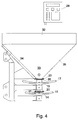
- the centrifugal fertilizer spreader according to Figures 3 and 4 differs from that Centrifugal fertilizer spreader according to FIGS. 1 and 2 first of all in that the Storage containers 30, 31 and 32 not next to each other but next to each other are arranged.
- the lower funnel ends 33 of the storage containers 30, 31 and 32 are located at the same height.
- the front and rear hopper walls 34 and 35 of the Storage containers 30, 31 and 32 are aligned with one another when viewed from the side.
- the lower ends 33 of the storage containers 30, 31 and 32 are metering devices 20 assigned the material to these storage containers 30, 31 and 32nd assigned centrifugal disks 14, 15 with throwing blades 16, 17, which in The disc level can be adjusted in different angles.
- the centrifugal disks 15 assigned to the outer storage containers 31 and 32 are arranged higher than those assigned to the middle reservoir 30 Centrifugal discs 15.
- the lower funnel ends 33 of the middle Storage container 30 assigned centrifugal disks 14 are those of the lower funnel ends 33 to the lower centrifugal discs 15 and conductive Supply shafts 36 assigned guide elements. At the bottom At the end of each supply shaft 36 there is a metering device 20 Feed shafts 36 are from the funnel ends 33 of the middle one Storage container 30 to the side and down.
- the metering elements 20 correspond to the metering elements according to the centrifugal spreader in Fig. 1 and 2.
- the centrifugal fertilizer spreader according to Figures 5 and 6 differs from that Centrifugal broadcaster according to the Fig.1 and 2 first in that the Storage containers 37, 38 and 39 are arranged side by side.
- the lower Funnel ends 40 are at the same height.
- the lower ends 40 of the Storage containers 37, 38 and 39 are associated with metering elements 20 that hold the material the centrifugal disks 15 associated with these storage containers 37, 38 and 39 Throwing blades 17, the disc plane in different angular positions can be adjustable, feed. All centrifugal disks 15 with the Throwing blades 17 which are assigned to the individual storage containers are the same educated.
- the different throwing distances and working widths of the individual The centrifugal discs or the centrifugal fertilizer spreader are different speeds of the centrifugal disks 15, which over the Hydraulic motors 19 which are connected to a control device and via a On-board computer system 28 are controlled and regulated, realized.
- stirring elements Above the Dosing elements are arranged stirring elements, which on the hydraulic motors 27th are driven.
- the setting devices 23 are assigned to the dosing members 20. Furthermore, the metering elements or the centrifugal disks 15 Adjustment devices can be assigned, by means of which the feed surface of the the metering elements on the centrifugal discs of the material set or can be changed in order to adjust the throwing distance and To carry out spreading material distribution.
Landscapes
- Life Sciences & Earth Sciences (AREA)
- Soil Sciences (AREA)
- Environmental Sciences (AREA)
- Fertilizing (AREA)
Applications Claiming Priority (4)
| Application Number | Priority Date | Filing Date | Title |
|---|---|---|---|
| DE19745440 | 1997-10-15 | ||
| DE19745440 | 1997-10-15 | ||
| DE19748876 | 1997-11-06 | ||
| DE19748876A DE19748876A1 (de) | 1997-10-15 | 1997-11-06 | Schleuderstreuer |
Publications (1)
| Publication Number | Publication Date |
|---|---|
| EP0910939A1 true EP0910939A1 (fr) | 1999-04-28 |
Family
ID=26040822
Family Applications (1)
| Application Number | Title | Priority Date | Filing Date |
|---|---|---|---|
| EP98117952A Withdrawn EP0910939A1 (fr) | 1997-10-15 | 1998-09-22 | Epandeur centrifuge |
Country Status (1)
| Country | Link |
|---|---|
| EP (1) | EP0910939A1 (fr) |
Cited By (6)
| Publication number | Priority date | Publication date | Assignee | Title |
|---|---|---|---|---|
| EP1090542A3 (fr) * | 1999-10-09 | 2001-09-26 | Amazonen-Werke H. Dreyer GmbH & Co. KG | Epandeur centrifuge |
| WO2002094004A3 (fr) * | 2001-04-02 | 2003-04-10 | Amazonen Werke Dreyer H | Epandeur d'engrais centrifuge |
| US11744169B2 (en) | 2019-11-14 | 2023-09-05 | Cnh Industrial Canada, Ltd. | Particulate material metering system for an agricultural implement |
| US11765991B2 (en) | 2019-11-14 | 2023-09-26 | Cnh Industrial Canada, Ltd. | Particulate material metering system for an agricultural implement |
| US12268119B2 (en) | 2011-03-10 | 2025-04-08 | Cnh Industrial Canada, Ltd. | Agricultural metering system having multiple meter rollers |
| US12349614B2 (en) | 2021-11-10 | 2025-07-08 | Deere & Company | Air seeding turn compensation using yaw rate from sensor on towing vehicle |
Citations (6)
| Publication number | Priority date | Publication date | Assignee | Title |
|---|---|---|---|---|
| EP0246575A2 (fr) * | 1986-05-23 | 1987-11-25 | Amazonen-Werke H. Dreyer GmbH & Co. KG | Distributeur à disques avec trémie |
| EP0278251A1 (fr) * | 1987-01-24 | 1988-08-17 | Amazonen-Werke H. Dreyer GmbH & Co. KG | Epandeur à disques centrifuges |
| DE3739265A1 (de) * | 1987-11-20 | 1989-06-01 | Amazonen Werke Dreyer H | Schleuderstreuer |
| EP0472855A1 (fr) * | 1990-08-25 | 1992-03-04 | Rauch Landmaschinenfabrik GmbH | Méthode d'étalonnage d'un distributeur d'engrais |
| EP0497166A1 (fr) * | 1991-01-31 | 1992-08-05 | Amazonen-Werke H. Dreyer GmbH & Co. KG | Epandeur centrifuge |
| DE4417549A1 (de) * | 1994-05-19 | 1995-11-23 | Bosch Gmbh Robert | Anordnung zur Dosierung und Verteilung von Streugut |
-
1998
- 1998-09-22 EP EP98117952A patent/EP0910939A1/fr not_active Withdrawn
Patent Citations (6)
| Publication number | Priority date | Publication date | Assignee | Title |
|---|---|---|---|---|
| EP0246575A2 (fr) * | 1986-05-23 | 1987-11-25 | Amazonen-Werke H. Dreyer GmbH & Co. KG | Distributeur à disques avec trémie |
| EP0278251A1 (fr) * | 1987-01-24 | 1988-08-17 | Amazonen-Werke H. Dreyer GmbH & Co. KG | Epandeur à disques centrifuges |
| DE3739265A1 (de) * | 1987-11-20 | 1989-06-01 | Amazonen Werke Dreyer H | Schleuderstreuer |
| EP0472855A1 (fr) * | 1990-08-25 | 1992-03-04 | Rauch Landmaschinenfabrik GmbH | Méthode d'étalonnage d'un distributeur d'engrais |
| EP0497166A1 (fr) * | 1991-01-31 | 1992-08-05 | Amazonen-Werke H. Dreyer GmbH & Co. KG | Epandeur centrifuge |
| DE4417549A1 (de) * | 1994-05-19 | 1995-11-23 | Bosch Gmbh Robert | Anordnung zur Dosierung und Verteilung von Streugut |
Cited By (6)
| Publication number | Priority date | Publication date | Assignee | Title |
|---|---|---|---|---|
| EP1090542A3 (fr) * | 1999-10-09 | 2001-09-26 | Amazonen-Werke H. Dreyer GmbH & Co. KG | Epandeur centrifuge |
| WO2002094004A3 (fr) * | 2001-04-02 | 2003-04-10 | Amazonen Werke Dreyer H | Epandeur d'engrais centrifuge |
| US12268119B2 (en) | 2011-03-10 | 2025-04-08 | Cnh Industrial Canada, Ltd. | Agricultural metering system having multiple meter rollers |
| US11744169B2 (en) | 2019-11-14 | 2023-09-05 | Cnh Industrial Canada, Ltd. | Particulate material metering system for an agricultural implement |
| US11765991B2 (en) | 2019-11-14 | 2023-09-26 | Cnh Industrial Canada, Ltd. | Particulate material metering system for an agricultural implement |
| US12349614B2 (en) | 2021-11-10 | 2025-07-08 | Deere & Company | Air seeding turn compensation using yaw rate from sensor on towing vehicle |
Similar Documents
| Publication | Publication Date | Title |
|---|---|---|
| EP0578988B2 (fr) | Dispositif pour épandre des matériaux en agriculture | |
| EP0330839B1 (fr) | Epandeur centrifuge | |
| EP0445842A1 (fr) | Distributeur d'engrais centrifuge avec trémie | |
| EP0540889B2 (fr) | Epandeur d'engrais centrifuge | |
| EP0820219B1 (fr) | Epandeur d'engrais centrifuge | |
| EP0545894B1 (fr) | Epandeur centrifuge | |
| EP0497166A1 (fr) | Epandeur centrifuge | |
| DE4134315A1 (de) | Schleuderduengerstreuer | |
| DE60300291T2 (de) | Abgabevorrichtung für Substanzen zum landwirtschaftlichen Gebrauch | |
| EP1542525B1 (fr) | Distributeur d'engrais centrifuge | |
| EP0870423A1 (fr) | Méthode pour déposer un seul fertilisant, ou bien plusieurs en même temps, avec un épandeur d'engrais | |
| DE19748876A1 (de) | Schleuderstreuer | |
| EP0613613A1 (fr) | Epandeur centrifuge | |
| EP0916247A1 (fr) | Epandeur centrifuge | |
| DE19802658A1 (de) | Verteilmaschine | |
| EP0379103A1 (fr) | Epandeur centrifuge | |
| DD297905A5 (de) | Schleuderduengerstreuer | |
| EP0386540B1 (fr) | Système de fabrication d'une série d'épandeurs de capacité croissante | |
| EP0791286A2 (fr) | Epandeur centrifuge | |
| DE19829782A1 (de) | Verfahren zum Einstellen eines Zentrifugaldüngerstreuers | |
| EP0901748A1 (fr) | Méthode d'utilisation d'un distributeur centrifuge | |
| DE19652907A1 (de) | Schleuderdüngerstreuer | |
| DE3533585A1 (de) | Dreipunktanbaumaschine zum ausbringen von koernigem material | |
| DE102010016871A1 (de) | Schleuderstreuer | |
| EP0904682A1 (fr) | Epandeur centrifuge |
Legal Events
| Date | Code | Title | Description |
|---|---|---|---|
| PUAI | Public reference made under article 153(3) epc to a published international application that has entered the european phase |
Free format text: ORIGINAL CODE: 0009012 |
|
| AK | Designated contracting states |
Kind code of ref document: A1 Designated state(s): DE FR GB |
|
| AX | Request for extension of the european patent |
Free format text: AL;LT;LV;MK;RO;SI |
|
| 17P | Request for examination filed |
Effective date: 19991015 |
|
| AKX | Designation fees paid |
Free format text: DE FR GB |
|
| STAA | Information on the status of an ep patent application or granted ep patent |
Free format text: STATUS: THE APPLICATION HAS BEEN WITHDRAWN |
|
| 18W | Application withdrawn |
Withdrawal date: 20000721 |