EP0386962A2 - Ultradünne sich selbst ausbildende molekulare Filme, Vorrichtung und Verfahren zu ihrer Herstellung und ihre Aufbringung auf Oberflächen - Google Patents
Ultradünne sich selbst ausbildende molekulare Filme, Vorrichtung und Verfahren zu ihrer Herstellung und ihre Aufbringung auf Oberflächen Download PDFInfo
- Publication number
- EP0386962A2 EP0386962A2 EP90302259A EP90302259A EP0386962A2 EP 0386962 A2 EP0386962 A2 EP 0386962A2 EP 90302259 A EP90302259 A EP 90302259A EP 90302259 A EP90302259 A EP 90302259A EP 0386962 A2 EP0386962 A2 EP 0386962A2
- Authority
- EP
- European Patent Office
- Prior art keywords
- film
- forming solution
- liquid
- aqueous liquid
- holding means
- Prior art date
- Legal status (The legal status is an assumption and is not a legal conclusion. Google has not performed a legal analysis and makes no representation as to the accuracy of the status listed.)
- Withdrawn
Links
Images



Classifications
-
- B—PERFORMING OPERATIONS; TRANSPORTING
- B82—NANOTECHNOLOGY
- B82Y—SPECIFIC USES OR APPLICATIONS OF NANOSTRUCTURES; MEASUREMENT OR ANALYSIS OF NANOSTRUCTURES; MANUFACTURE OR TREATMENT OF NANOSTRUCTURES
- B82Y30/00—Nanotechnology for materials or surface science, e.g. nanocomposites
-
- C—CHEMISTRY; METALLURGY
- C08—ORGANIC MACROMOLECULAR COMPOUNDS; THEIR PREPARATION OR CHEMICAL WORKING-UP; COMPOSITIONS BASED THEREON
- C08J—WORKING-UP; GENERAL PROCESSES OF COMPOUNDING; AFTER-TREATMENT NOT COVERED BY SUBCLASSES C08B, C08C, C08F, C08G or C08H
- C08J5/00—Manufacture of articles or shaped materials containing macromolecular substances
- C08J5/18—Manufacture of films or sheets
-
- B—PERFORMING OPERATIONS; TRANSPORTING
- B05—SPRAYING OR ATOMISING IN GENERAL; APPLYING FLUENT MATERIALS TO SURFACES, IN GENERAL
- B05D—PROCESSES FOR APPLYING FLUENT MATERIALS TO SURFACES, IN GENERAL
- B05D1/00—Processes for applying liquids or other fluent materials
- B05D1/18—Processes for applying liquids or other fluent materials performed by dipping
- B05D1/20—Processes for applying liquids or other fluent materials performed by dipping substances to be applied floating on a fluid
-
- B—PERFORMING OPERATIONS; TRANSPORTING
- B05—SPRAYING OR ATOMISING IN GENERAL; APPLYING FLUENT MATERIALS TO SURFACES, IN GENERAL
- B05D—PROCESSES FOR APPLYING FLUENT MATERIALS TO SURFACES, IN GENERAL
- B05D1/00—Processes for applying liquids or other fluent materials
- B05D1/18—Processes for applying liquids or other fluent materials performed by dipping
- B05D1/20—Processes for applying liquids or other fluent materials performed by dipping substances to be applied floating on a fluid
- B05D1/202—Langmuir Blodgett films (LB films)
- B05D1/206—LB troughs
-
- B—PERFORMING OPERATIONS; TRANSPORTING
- B29—WORKING OF PLASTICS; WORKING OF SUBSTANCES IN A PLASTIC STATE IN GENERAL
- B29C—SHAPING OR JOINING OF PLASTICS; SHAPING OF MATERIAL IN A PLASTIC STATE, NOT OTHERWISE PROVIDED FOR; AFTER-TREATMENT OF THE SHAPED PRODUCTS, e.g. REPAIRING
- B29C39/00—Shaping by casting, i.e. introducing the moulding material into a mould or between confining surfaces without significant moulding pressure; Apparatus therefor
- B29C39/14—Shaping by casting, i.e. introducing the moulding material into a mould or between confining surfaces without significant moulding pressure; Apparatus therefor for making articles of indefinite length
-
- B—PERFORMING OPERATIONS; TRANSPORTING
- B29—WORKING OF PLASTICS; WORKING OF SUBSTANCES IN A PLASTIC STATE IN GENERAL
- B29C—SHAPING OR JOINING OF PLASTICS; SHAPING OF MATERIAL IN A PLASTIC STATE, NOT OTHERWISE PROVIDED FOR; AFTER-TREATMENT OF THE SHAPED PRODUCTS, e.g. REPAIRING
- B29C39/00—Shaping by casting, i.e. introducing the moulding material into a mould or between confining surfaces without significant moulding pressure; Apparatus therefor
- B29C39/22—Component parts, details or accessories; Auxiliary operations
- B29C39/42—Casting under special conditions, e.g. vacuum
-
- B—PERFORMING OPERATIONS; TRANSPORTING
- B82—NANOTECHNOLOGY
- B82Y—SPECIFIC USES OR APPLICATIONS OF NANOSTRUCTURES; MEASUREMENT OR ANALYSIS OF NANOSTRUCTURES; MANUFACTURE OR TREATMENT OF NANOSTRUCTURES
- B82Y40/00—Manufacture or treatment of nanostructures
-
- C—CHEMISTRY; METALLURGY
- C08—ORGANIC MACROMOLECULAR COMPOUNDS; THEIR PREPARATION OR CHEMICAL WORKING-UP; COMPOSITIONS BASED THEREON
- C08J—WORKING-UP; GENERAL PROCESSES OF COMPOUNDING; AFTER-TREATMENT NOT COVERED BY SUBCLASSES C08B, C08C, C08F, C08G or C08H
- C08J7/00—Chemical treatment or coating of shaped articles made of macromolecular substances
- C08J7/04—Coating
Definitions
- This application relates to ultra-thin films, and to apparatus and methods for making such films.
- the invention is more particularly but not exclusively applicable to self-assembling molecular films and will be described with particular reference thereto. However, it will be appreciated that the invention has broader aspects and can be used for making other types of films, such as polymer thin films.
- self-assembling molecular film means one in which the molecules self-assemble into an ordered film.
- An ultra-thin self-assembling molecular film has ordered amphiphilic molecules that are oriented relative to one another in two directions.
- a film of this type is formed by confining the film during its formation in such a manner that the molecules are ordered in two directions, and are not allowed to become randomly disoriented, as they do in known techniques.
- the present invention provides a film made from a film-forming solution containing amphiphilic molecules in which the molecules are ordered in the film and are arranged in the film in a plurality of aligned units, and the aligned units are oriented relative to one another in two directions.
- a self-assembling molecular fluid membrane is prepared by delivering a substantially continuous curtain of film-forming solution containing amphiphilic molecules to a surface of an aqueous liquid, confining the film-forming solution against movement in all but one direction along the said surface, whereby the film-forming solution solidifies into a self-assembling molecular fluid membrane in which the molecules are ordered and arranged in aligned units that are themselves oriented relative to one another in two directions generally parallel to the said surface.
- apparatus for manufacturing film from a film-forming solution containing amphiphilic molecules comprises liquid-holding means for holding an aqueous liquid having a liquid surface and on which a film-forming solution containing amphiphilic molecules is solidifiable, the said liquid-holding means having side boundaries at opposite ends of a width dimension extending substantially perpendicular to a film-forming direction, and delivery means for delivering a film-forming solution containing amphiphilic molecules to the liquid-holding means in a substantially continuous thin stream extending substantially continuously across the said width dimension, whereby the solution floats in an aqueous liquid held by the liquid-holding means and solidifies into a self-assembling molecular thin film with its molecules ordered throughout the film and arranged in a plurality of aligned units that are oriented in a direction substantially perpendicular to the liquid surface and in a direction substantially parallel to the film-forming direction.
- a film-forming solution containing amphiphilic molecules and solvent is delivered to an aqueous or other liquid.
- the solvent dissolves in the liquid and leaves behind the pure amphiphilic molecules on the surface of the aqueous liquid to solidify into an ultra-thin, self-assembling molecular film.
- the amphiphilic molecules from the film-forming solution self-assemble in their natural equilibrium condition.
- Film made in accordance with the present application can have anywhere from 0 to 100% crystallinity.
- the percentage of molecules that will crystallise in the film can be controlled by adding chemicals that reduce the crystallising action.
- the film Even though the film has very little actual crystallinity or is completely amorphous, the film still has aligned regions under an optical microscope.
- the ordered nature of the molecules can be determined by x-ray diffraction, and the orientation of the crystals can be determined by use of an optical microscope.
- aligned units For convenience of description, whether the film is one having actual crystals or simply aligned regions in an amorphous state, the crystals and regions will be referred to as aligned units.
- reference to an ultra-thin, self-assembling molecular membrane or film is intended to include an amorphous type of film having aligned units that look like crystals but really are not true crystals.
- Film made in accordance with the present application can be applied to glass, ceramic, or porcelain surfaces.
- the film can also be applied to metal, plastics, and other substrate surfaces to protect and modify such surfaces.
- polypropylene packaging does not accept many types of ink and film of the present application can be applied to the packaging for printing on the film with these inks.
- Film of the present application is also a very good anti-corrosion coating for metals.
- the film of the present application can be applied to substrates in its ultra-thin, self-assembling molecular membrane or film structure in which each molecule can move up and down perpendicular to the plane of the film but cannot rotate or move in other directions. This helps each molecule to attach and freeze in place on the substrate surface.
- the polar groups of the film are adsorbed to a substrate surface by forces that include chemical bonding, dipolar attraction, hydrogen bonding and van der Waals forces. The film is then dried in situ on the substrate surface.
- Film made in accordance with the present invention can form simultaneous multilayers of individual self-assembling molecular films separated from one another by a thin film of a liquid.
- the number of layers formed, and the thickness of the film can be varied by controlling the rate at which additional film-forming solution is delivered and the rate at which solidified film is removed.
- the film-forming solution can be delivered above or below an aqueous liquid for solidification on the surface of the aqueous liquid.
- Stacked self-assembling molecular films from different film-forming solutions can be formed to provide a film having layers of different materials. Solidified film is removed from an aqueous liquid by lifting the film at an angle preferably less than 30 o in order to minimise the possibility of disrupting the self-assembling molecular nature of the film.
- the film of the present invention is thus an ultra-thin, self-assembling molecular film that has better properties than previously known films.
- the apparatus and method of the present invention make such a film in a relatively simple, economical and continuous manner, which was not possible before.
- Figure 1 shows a liquid-holding means A that may take many forms, and is illustrated as a generally rectangular trough having end walls 10, 12 and substantially parallel opposite side walls 14, 16.
- Liquid-holding means A holds an aqueous liquid 20 that may be distilled water or water having certain other substances dissolved therein.
- aqueous liquid 20 may be distilled water or water having certain other substances dissolved therein.
- glycerol may be mixed with water to vary the density of the aqueous liquid.
- liquid 20 is of type for which polar groups of amphiphilic molecules have a strong affinity.
- Delivery means B for film-forming solution extends substantially completely across liquid-holding means A between its side walls 14 and 16 and closely adjacent to one end 12.
- Delivery means B includes an elongated outlet or slit 22 extending substantially completely and continuously across the entire width of liquid holding means A between side walls 14 and 16.
- An elongated porous member 24 can be provided to cover or fill the delivery slit for the film-forming solution.
- TH provides a diffuser for reducing the velocity and increasing the static pressure of the film-forming solution passing through it.
- the porous member can be a fabric wick, or can be an open-cell porous material such as air stone or sponge.
- outlet or slit 22 and diffuser 24 extend substantially continuously and completely across the entire width of liquid holding means A
- outlet or slit 22 and diffuser 24 extend substantially continuously and completely across the entire width of liquid holding means A
- Delivery means B can simply be an elongated tube with closed ends and having an elongated longitudinally extending outlet slit.
- internal baffles or variations in the cross-sectional area of the passages can be provided for enabling substantially uniform delivery of film-forming solution across the entire width of the delivery means and the liquid-holding means.
- Film-forming solution is delivered through a suitable conduit 26 and adjustable valve 28 to delivery means B. This makes it possible to vary the delivery rate of the film-forming solution and to vary the pushing force provided on the solidified film being formed. Obviously, other arrangements, such as a variable speed pump, can also be provided to vary the delivery rate of the film-forming solution.
- outlet 22 and diffuser 24 are located beneath the upper surface of aqueous liquid 20.
- solvent in the film-forming solution dissolves in aqueous liquid 20 instead of flashing off into the atmosphere.
- End 10 of liquid-holding means A can be slightly smaller in height than end 12 so that aqueous liquid 20 would continuously flow at a slow rate over end 10.
- a suitable inlet is then provided for liquid holding means A to continuously supply fresh or reconditioned aqueous liquid 20 to liquid holding means A.
- film-forming solution 30 As film-forming solution 30 is delivered into aqueous liquid 20 by delivery means B, it floats to the surface of aqueous liquid 20 and solidifies into a self-assembling molecular film C.
- Film pick-up or removal means is provided for removing film C from the surface of aqueous liquid 20.
- a roll 34 of plastics or metal foil, wax paper, release grade polyethylene, or polymeric material having a release grade silicone or polyethylene layer on its surface is provided.
- the roll of material 34 provides a web 36 extending substantially completely across the width of liquid-holding means A between side walls 14 and 16.
- Web 36 travels around a roll 38 and then to a take-up roll 40 mounted by adjustable mounting means such as elongated slots 42 in mounting members 44. Adjustment of take-up roll 40 makes it possible to vary the pick-up angle 50 between the upper surface of aqueous liquid 20 and external web portion 36a. Angle 50 is desirably less than 45 o , and is preferably less than 30 o .
- An adjustable angular velocity detector 52 may be connected with roll 38 and with a variable speed drive motor 54 for take-up roll 40 in order to provide movement of web 36 at a substantially constant velocity. Adjustment of angular velocity detector 52 makes it possible to increase or decrease the velocity of the web to vary the rate at which film C is removed from aqueous liquid 20. Solidified self-assembling molecular film C attaches itself to web 36 by molecular attraction and travels with web 36 to take-up roll 40.
- this is made possible by extruding the film-forming solution through a very narrow slit to shear the film-forming solution as it is delivered, and also by delivering the film-forming solution across substantially the entire width of liquid-holding means A between side walls 14 and 16. With the film-forming solution extending in a substantially continuous curtain across the entire width of liquid-holding means A as it is delivered by delivery means B, solidification takes place with the film and film-forming solution transversely confined between side walls 14 and 16.
- Figure 3 shows film C having polar groups 60 on amphiphilic molecules attracted to aqueous liquid 20, while non-polar groups 62 extend away from aqueous liquid 20.
- Figure 4 shows molecules 70 as being ordered within film C.
- molecules 70 self-assemble in their natural equilibrium ordered condition.
- the molecules are ordered in the sense that they are assembled in a uniform relationship relative to one another as opposed to being randomly distributed in a disordered manner.
- Molecules are ordered on a micron (micrometre) level, which can be determined by x-ray diffraction.
- Molecules 70 arrange themselves into crystals or aligned units 72 in Figure 5. Although many aligned units are not crystals, they appear to be crystals when viewed with an optical microscope. Therefore, whether the molecules are arranged in crystals or only aligned units, both arrangements will be referred to as aligned units 72.
- Aligned units 72 are oriented relative to one another in both x and y directions, that is, in a direction parallel to film-forming direction x and in direction y transverse or perpendicular to film-forming direction x. By confining the film-forming solution between side walls 14 and 16, aligned units 72 are made to orient themselves relative to one another both longitudinally and transversely of liquid-holding means A. This provides a solidified film having more uniform properties than previously possible.
- Figure 6 shows a prior arrangement in which a drop or supply of film-forming solution 80 placed on the surface of an aqueous liquid solidifies into a thin film having units 82 that are completely disoriented and randomly distributed relative to one another.
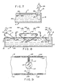
- Figure 7 shows film C as including a plurality of individual layers or membranes 90, 92 and 94. It has been found that film-forming solution 30 delivered by delivery means B simultaneously forms multilayers 90, 92 and 94. It is not completely understood how this takes place, but it seems to be analogous to the bubble-formation phenomenon. It is possible that additional layers form below and/or above an initial layer. In any case, it has been found that a plurality of individual layers forms and these layers are separated from one another by an extremely thin film or bearing layer of aqueous liquid.
- the number of layers 90, 92, 94 that are formed, and thereby the thickness of film C can be varied by varying the delivery rate of film-forming solution 30, and/or by varying the rate at which solidified film C is removed from the aqueous liquid. Obviously, both delivery and removal can be controlled to vary the film thickness and the number of layers or self-assembling molecular membranes that are formed.
- the film-forming solution 30 provided by delivery means B provides a pushing force on film C as it solidifies, while the pick-up or removal means provides a pulling force on such film. At least one of such forces is varied to vary the film thickness and the number of simultaneous multilayers that are formed.
- Each layer 90, 92, 94 is a monomolecular membrane, and such membranes are assembled to form a multi-molecular film C.
- Figures 8 and 9 show a pair of spaced-apart chains 102, 104 extending around sprockets 105-107, at least one pair of which is rotatably driven.
- Small article holding means in Figure 9 includes clamps 108 that are clamped on chains 104 and have oppositely disposed arcuate supports 110 connected with clamps 108 by telescoping spring loaded connections 112.
- Spring loaded connections 112 yieldably bias arcuate supports 110 toward one another.
- An article 114 is shown as being held between supports 110. As articles 114 travel through film C, a coating of film C attaches to the surfaces of the articles.
- Film removal means D is shown as being in the form of a continuous web 120 extending around rollers 121-123, at least one of which is rotatably driven by a variable speed motor 124. Film removed from aqueous liquid 20 by removal means D can simply be discarded if so desired. This arrangement makes it possible to vary the thickness of film C and thereby the coating thickness applied to articles 114.
- Drying means 130 may be provided above articles 114 after they have been coated by film C.
- the conveyor chains can be arranged in an elongated path with heating means 130 located remote from liquid holding means A where articles 114 can be removed and inserted.
- the small articles that are provided with a film coating can be of many types, such as lenses.
- Figure 10 shows another arrangement wherein a layer 140 of a solvent such as octane or hexane or other alkanes that water is positioned on one side of delivery means B and end wall 10.
- Layer 140 floats on aqueous liquid 20 to provide an interface 142 therewith.
- the outlet slit for film-forming solution delivery means B and the diffuser 24 are located for delivering film-forming solution 30 within layer 140.
- the film-forming solution 30 then sinks through layer 140 to interface 142 where it solidifies into thin film C.
- the film-forming solution can also be delivered into an aqueous liquid layer depending upon the film-forming substrate used by lowering the diffuser 24 in the water layer. This then will form the thin film at the interface.
- the arrangement of Figure 10 has been shown shortened for convenience of illustration and it will be recognized that it could be elongated to have the removal means for removing film at a predetermined rate to vary the thickness thereof.
- the film-forming solution 30 can be comprised of silanes.
- the arrangement of Figure 10 makes it possible to solidify film in an anerobic environment, and the solvent used in the film-forming solution can be polar or non-polar.
- Figure 11 shows another arrangement wherein a layer 20 of aqueous liquid floats on a bottom layer 150 having a density greater than water.
- layer 150 can be a phenylmethyl polysiloxane.
- One brand of such material is available as 710 fluid from Dow Corning. This liquid has a density of approximately 1.11 grams per milliliter and is immiscible in water.
- Film-forming solution delivery means B is positioned with its outlet and diffuser 24 located for deliverying film-forming solution 30 within layer 150. Film-forming solution 30 then rises to interface 152 between layers 20, 150 where film C solidifies with the polar groups 60 of the amphiphilic molecules attracted to layer 20. This is another arrangement that makes it possible to solidify film C in an anaerobic environment.
- Figure 12 shows another arrangement wherein a plurality of layers 20 of aqueous liquid are separated from one another by a plurality of layers 150 of a liquid having a density greater than water and being immiscible in water.
- the densities of the various layers can be adjusted as by adding various amounts of glycerol to the aqueous liquid, and by adding octane or hexane to the other layers.
- Film-forming solution delivery means B is provided with two different valves 28, 28a for supplying two different types of film-forming solutions through outlet slits and diffusers 24, 24a. This makes it possible to simultaneously form two films C and C′ from one outlet or diffuser 24, and two additional different films Ca and Ca′ from the other delivery diffuser 24a. These different films can be removed in the manner described with reference to Figures 1 and 2, and can be used for coating articles as suggested with reference to Figures 8-10.
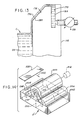
- Figure 13 shows another arrangement wherein film-forming solution 30 is fed to a transversely elongated reservoir 170 in a delivery means 172 that extends substantially completely across the side walls of a liquid- holding means adjacent to one end of it.
- a spillway 174 is provided over which film-forming solution 30 can flow in a substantially continuous curtain 176 to the surface of aqueous liquid 30 for solidification into film C.
- a fabric member 180 completely covering spillway 174, and extending from reservoir 170 to a location beneath the surface of aqueous liquid 20 defines flow-enhancing means for enhancing the flow of film-forming solution 30 without having any localized disruptions therein.
- Flow-enhancing means 180 can be a woven fabric such as cotton and can also take other forms. A woven cotton fabric is a particularly good flow-enhancing means.
- Figure 14 shows another arrangement wherein liquid-holding means A′ is divided into two compartments as by a divider 200.
- One compartment 202 holds an aqueous liquid while the other compartment 204 holds a film-forming solution.
- Rotatable roller 206 is mounted for engaging an aqueous liquid within compartment 202.
- Roller 208 is rotatably mounted for engaging film-forming solution within compartment 204.
- Roller 210 is rotatably mounted between rollers 206, 208 and in an engagement therewith.
- Roller 210 is suitably rotatably driven as by a variable speed motor 212.
- Rollers 206-210 may be drivingly connected with one another as by belts 214, 216 extending around pulleys on the ends of the rollers, or they may be driven by engagement with one another.
- Belts 214, 216 are preferably twisted to impart rotation of rollers 206, 208 in a direction reverse to that of roller 210. Clockwise rotation of roller 210 results in counterclockwise rotation of 206 which transfers an aqueous liquid from compartment 202 onto the surface of roller 210. Thus, roller 210 and its outer surface becomes a movable liquid holding means for holding an aqueous liquid on which film-forming solution may solidify.
- roller 208 rotates in a counterclockwise direction and transfers film-forming solution from compartment 204 onto the layer of aqueous liquid on roller 210.
- the film-forming solution solidifies on roller 210, it engages the surface of a substrate 220 moving longitudinally past roller 210 as indicated by arrow 222.
- the polar groups of the self-assembling molecular film attach themselves to the surface of substrate 220 for providing a coating thereon.
- Substrate 220 may be a web for storing the film or may be an article to be coated with the film.
- Rollers 206, 208 can be independently driven by individual variable speed motors.
- the pulleys are preferably arranged such that roller 208 is rotating at a greater velocity than roller 210.
- This provides longitudinal shearing action on the film-forming solution as it is being delivered from roller 208 to roller 210, and this helps to provide ordering of the molecules and orientation of the aligned units.
- a doctor blade or the like can be provided for obtaining a uniform film of aqueous liquid on the outer surface of roller 210.
- the film-forming apparatus shown in Figure 14 can be duplicated on the opposite side of substrate 220 for providing a self-assembling molecular film on both opposite surfaces thereof simultaneously.
- Film-forming solutions used in accordance with the present application can be made by dissolving an amphiphilic material or "amphiphile,” having low solubility and volatility, into a low-boiling organic solvent, such as chloroform, hexane, methylene chloride or the like, or into a polar solvent, such as ethanol, acetone, propylene carbonate or the like.
- a low-boiling organic solvent such as chloroform, hexane, methylene chloride or the like
- a polar solvent such as ethanol, acetone, propylene carbonate or the like.
- Materials that can be used to form film in accordance with the present application include, but are not necessarily limited to, the following:
- amphiphiles which include carboxylic acid (-COOH) groups, or their associated salts, as the major polar component.
- the apolar component typically consists of a long linear alkane segment. Examples include brassidic acid, elaidic acid, stearic acid, arachic acid, and other naturally occurring fatty acids, as well as synthetic compounds which include diacetylene, vinyl-unsaturated, or fused linear or branched aromatic residues within the apolar regions. (A balance must be achieved, as is well known to those skilled in the art, between the length of the alkane or aromatic apolar residues, and the acid residue, in order to provide true monolayer-forming character on a water surface.)
- amphiphiles which include alcohol (-OH) groups as the major polar component.
- the apolar component typically consists of a long linear alkane segment. Examples include brassidic alcohol, elaidic alcohol, stearic alcohol, arachic alcohol, and other fatty alcohols, as well as synthetic alcohol compounds, which include diacetylene, vinyl-unsaturated, or fused linear or branched aromatic residues within the apolar regions.
- amphiphiles which include amide (-NHCO) groups as the major polar component.
- the apolar component typically consists of a long linear alkane segment. Examples include brassidic amide, elaidic amide, stearic amide, arachic amide, and other fatty amides, as well as synthetic amide compounds, which include diacetylene, vinyl-unsaturated, or fused linear or branched aromatic residues within the apolar regions.
- amphiphiles which include primary (-NH2), secondary (-NHR), or tertiary amine (-NR2) groups as the major polar component.
- the apolar component typically consists of a long linear alkane segment. Examples include brassidic amine, elaidic amine, stearic amine, arachic amine, and other fatty amines, as well as synthetic amine compounds, which include diacetylene, vinyl-unsaturated, or fused linear or branched aromatic residues within the apolar regions.
- amphiphiles which include cyanide (-CN) groups as the major polar component.
- the apolar component typically consists of a long linear alkane segment. Examples include brassidic cyanide, elaidic cyanide, stearic cyanide, arachic cyanide, and other fatty cyanides, as well as synthetic cyanide compounds, which include diacetylene, vinyl-unsaturated, or fused linear or branched aromatic residues within the apolar regions.
- amphiphiles which include nitrate (-NO2) groups as the major polar component.
- the apolar component typically consists of a long linear alkane segment. Examples include brassidic nitrate, elaidic nitrate, stearic nitrate, arachic nitrate, and other fatty nitrates, as well as synthetic nitrate compounds, which include diacetylene, vinyl-unsaturated, or fused linear or branched aromatic residues within the apolar regions.
- amphiphiles which include phosphate (-PO4) groups as the major polar component.
- the apolar component typically consists of a long linear alkane segment. Examples include brassidic phosphate, elaidic phosphate, stearic phosphate, arachic phosphate, and other fatty phosphates, as well as synthetic phosphate compounds, which include diacetylene, vinyl-unsaturated, or fused linear or branched aromatic residues within the apolar regions.
- amphiphiles which include sulphonate (-SO3) groups as the major polar component.
- the apolar component typically consists of a long linear alkane segment. Examples include brassidic sulphonate, elaidic sulphonate, stearic sulphonate, arachic sulphonate, and other fatty sulphonates, as well as synthetic sulphonic compounds, which include diacetylene, vinyl-unsaturated, or fused linear or branched aromatic residues within the apolar regions.
- amphiphiles which include silanol Si-(X) n .
- X halogens, hydroxy, alkoxy, amine or imine or similar groups as the major polar component
- n 1-3.
- the apolar component typically consists of a long linear alkane segment. Examples include brassidic silane, elaidic silane, stearic silane, arachic silane, and other fatty silanes with alkyl chain C1-C16, as well as synthetic silane compounds, which include diacetylene, vinyl unsaturated, or fused linear or branched aromatic residues within the apolar regions.
- Silanes can be used to form film in an anaerobic environment, and the solvent used can be either polar or non-polar. The use of non-polar solvents was not heretofore possible.
- amphiphiles having, in their apolar regions, residues or structures comprising organic dyes with and without metal substituents (e.g., phthalocyanines, porphyrins, phenol blues, etc.), inorganic dyes (e.g., chromates, iron oxides, etc.), nonlinear oscillators (e.g., p-nitroanaline and derivates, etc.), and/or photoconductors (e.g., carbazoles, acridones, etc.) are also useful in accordance with the invention.
- organic dyes with and without metal substituents e.g., phthalocyanines, porphyrins, phenol blues, etc.
- inorganic dyes e.g., chromates, iron oxides, etc.
- nonlinear oscillators e.g., p-nitroanaline and derivates, etc.
- photoconductors e.g., carbazoles, acridones
- amphiphiles useful in accordance with the invention should be capable of forming a true self-assembling molecular layer on a water surface (water/gas or water/oil interface), when spread from a solvent.
- the amphiphiles useful in accordance with the invention must be virtually insoluble in aqueous media, at certain pHs, with/without certain salt types or concentrations added to the aqueous media.
- Nearly all commercial polymers can be used to form film in accordance with the present application including, but not limited to, polyesters, polycarbonates, polyamides and fluorocarbons. Materials that form self-assembling molecular multilayers are particularly advantageous to form film in accordance with the present application.
- a concentrated solution of such materials such as the foregoing preferred amphiphilic compounds
- concentrations of about 0.01 mg/ml to about 1000 mg/ml are utilized.
- solutions of a concentration of about 0.5 mg/ml to about 20 mg/ml are used.
- Film-forming solutions are made by dissolving a suitable amphiphile in a suitable low-boiling organic solvent.
- Usable solvents include, but are not limited to, chloroform, hexane and methylene chloride, and polar solvents such as ethanol, acetone and propylene carbonate.
- the monolayer formed from the film-forming solution was compressed in order to compress the molecules together in the plane of the film.
- the present application allows the molecules to assemble in their natural equilibrium state.
- the solvent in the film-forming solution preferably dissolves into an aqueous liquid instead of flashing off into the atmosphere.
- the ratio of the delivery rate of film-forming solution to the pick-up rate of solidified film is directly proportional to the film thickness and the number of layers in the film. It is desirable that the delivery means for the film-forming solution provides a pressure drop across the delivery slit that is very low, from 0 to 5 psi. (0 to 35 kPa).
- Film in accordance with the application comprises a plurality of aligned units arranged side-by-side and end-to-end. 100x examination using an optical microscope can be used to distinguish the ordered and oriented film of the present application from a single crystal in a prior art-type of film.
- Film made in accordance with the present application can be made in many different thicknesses, but is preferably less than about 6 microns thick. Film of the present application is also characterized by its uniform thickness throughout its area made possible by the monomolecular layers of uniform thickness being intimately attached to one another at their interfaces in a multilayer film.
Landscapes
- Chemical & Material Sciences (AREA)
- Engineering & Computer Science (AREA)
- Nanotechnology (AREA)
- Manufacturing & Machinery (AREA)
- Materials Engineering (AREA)
- Condensed Matter Physics & Semiconductors (AREA)
- Polymers & Plastics (AREA)
- Medicinal Chemistry (AREA)
- Health & Medical Sciences (AREA)
- Physics & Mathematics (AREA)
- Chemical Kinetics & Catalysis (AREA)
- Organic Chemistry (AREA)
- General Physics & Mathematics (AREA)
- Crystallography & Structural Chemistry (AREA)
- Composite Materials (AREA)
- Mechanical Engineering (AREA)
- Application Of Or Painting With Fluid Materials (AREA)
- Manufacture Of Macromolecular Shaped Articles (AREA)
Applications Claiming Priority (2)
| Application Number | Priority Date | Filing Date | Title |
|---|---|---|---|
| US32108889A | 1989-03-09 | 1989-03-09 | |
| US321088 | 1989-03-09 |
Publications (2)
| Publication Number | Publication Date |
|---|---|
| EP0386962A2 true EP0386962A2 (de) | 1990-09-12 |
| EP0386962A3 EP0386962A3 (de) | 1991-04-03 |
Family
ID=23249131
Family Applications (1)
| Application Number | Title | Priority Date | Filing Date |
|---|---|---|---|
| EP19900302259 Withdrawn EP0386962A3 (de) | 1989-03-09 | 1990-03-02 | Ultradünne sich selbst ausbildende molekulare Filme, Vorrichtung und Verfahren zu ihrer Herstellung und ihre Aufbringung auf Oberflächen |
Country Status (4)
| Country | Link |
|---|---|
| EP (1) | EP0386962A3 (de) |
| JP (1) | JPH02235936A (de) |
| KR (1) | KR900014473A (de) |
| AU (1) | AU4991690A (de) |
Cited By (6)
| Publication number | Priority date | Publication date | Assignee | Title |
|---|---|---|---|---|
| EP0759162A4 (de) * | 1994-05-10 | 1998-01-07 | Univ Illinois | Strukturen mit feldempfindlicher durchlässigkeitsregulierung |
| EP0663868B1 (de) * | 1991-10-10 | 1999-03-24 | nanoFILM, Ltd. | Verfahren und zusammensetzung zur aufbringung von dunnen filmen amphiphiler moleküle auf substrate |
| US7544483B2 (en) | 2002-06-14 | 2009-06-09 | Monier Tadros | Method for the production of protamine |
| WO2014070646A1 (en) | 2012-10-31 | 2014-05-08 | Pioneer Hi-Bred International, Inc. | Transformed plants having increased beta-carotene levels, increased half-life and bioavailability and methods of producing such |
| EP3189899A4 (de) * | 2014-09-02 | 2018-05-02 | Obshchestvo s Ogranichennoy Otvetstvennostyu "Izovac Technologies" | Vorrichtung zur herstellung nanostrukturierter beschichtungen auf einer festen oberfläche |
| WO2021071824A1 (en) * | 2019-10-07 | 2021-04-15 | The University Of Chicago | Large lateral scale two-dimensional materials and other thin films, and associated systems and methods |
Family Cites Families (7)
| Publication number | Priority date | Publication date | Assignee | Title |
|---|---|---|---|---|
| US2607081A (en) * | 1951-04-23 | 1952-08-19 | Du Pont | Inhibiting polymerization during preparation of synthetic resin sheets |
| FR2038632A5 (en) * | 1969-03-20 | 1971-01-08 | Rhone Poulenc Sa | Float production of thin polymer sheet |
| US3767737A (en) * | 1971-09-07 | 1973-10-23 | Gen Electric | Method for production casting of ultrathin polymer membranes |
| US3876738A (en) * | 1973-07-18 | 1975-04-08 | Amf Inc | Process for producing microporous films and products |
| JPS62129316A (ja) * | 1985-07-16 | 1987-06-11 | Kanegafuchi Chem Ind Co Ltd | ポリイミド前駆体を部分的に閉環させた薄膜 |
| DE3724364A1 (de) * | 1987-07-23 | 1989-02-02 | Hoechst Ag | Film aus mindestens einer monomolekularen schicht |
| US4970120A (en) * | 1987-07-25 | 1990-11-13 | Hoechst Aktiengesellschaft | Film comprising unimolecular layers |
-
1989
- 1989-11-15 JP JP1297244A patent/JPH02235936A/ja active Pending
-
1990
- 1990-02-07 KR KR1019900001448A patent/KR900014473A/ko not_active Withdrawn
- 1990-02-19 AU AU49916/90A patent/AU4991690A/en not_active Abandoned
- 1990-03-02 EP EP19900302259 patent/EP0386962A3/de not_active Withdrawn
Cited By (7)
| Publication number | Priority date | Publication date | Assignee | Title |
|---|---|---|---|---|
| EP0663868B1 (de) * | 1991-10-10 | 1999-03-24 | nanoFILM, Ltd. | Verfahren und zusammensetzung zur aufbringung von dunnen filmen amphiphiler moleküle auf substrate |
| EP0759162A4 (de) * | 1994-05-10 | 1998-01-07 | Univ Illinois | Strukturen mit feldempfindlicher durchlässigkeitsregulierung |
| US7544483B2 (en) | 2002-06-14 | 2009-06-09 | Monier Tadros | Method for the production of protamine |
| WO2014070646A1 (en) | 2012-10-31 | 2014-05-08 | Pioneer Hi-Bred International, Inc. | Transformed plants having increased beta-carotene levels, increased half-life and bioavailability and methods of producing such |
| EP3189899A4 (de) * | 2014-09-02 | 2018-05-02 | Obshchestvo s Ogranichennoy Otvetstvennostyu "Izovac Technologies" | Vorrichtung zur herstellung nanostrukturierter beschichtungen auf einer festen oberfläche |
| WO2021071824A1 (en) * | 2019-10-07 | 2021-04-15 | The University Of Chicago | Large lateral scale two-dimensional materials and other thin films, and associated systems and methods |
| US12030081B2 (en) | 2019-10-07 | 2024-07-09 | The University Of Chicago | Large lateral scale two-dimensional materials and other thin films, and associated systems and methods |
Also Published As
| Publication number | Publication date |
|---|---|
| AU4991690A (en) | 1990-09-13 |
| KR900014473A (ko) | 1990-10-24 |
| JPH02235936A (ja) | 1990-09-18 |
| EP0386962A3 (de) | 1991-04-03 |
Similar Documents
| Publication | Publication Date | Title |
|---|---|---|
| US5106561A (en) | Method of making film | |
| US5173365A (en) | Ultra-thin molecular film | |
| US7591905B2 (en) | Method and apparatus for two dimensional assembly of particles | |
| DE69505279T2 (de) | Methode und vorrichtung zum auftragen einer dünnen,flüssigen,gestreiften beschichtung | |
| US20110135834A1 (en) | Modular transfer apparatus and process | |
| CA2210077A1 (en) | Method and apparatus for applying thin fluid coatings | |
| DE60303509T2 (de) | Verfahren und vorrichtung zum zweidimensionalen aufbau von partikeln | |
| US20050118338A1 (en) | Control of the spatial distribution and sorting of micro-or nano-meter or molecular scale objects on patterned surfaces | |
| Fang | Ordered arrays of self-assembled lipid tubules: fabrication and applications | |
| EP1028816A1 (de) | Verfahren und vorrichtung zur herstellung von monoschichten aus partikeln oder molekülen | |
| JPH02235936A (ja) | 自己集合性極薄分子フィルム,並びにそれを作製するための,及びそれを表面に施すための装置と方法 | |
| Picard | Fine particle monolayers made by a mobile dynamic thin laminar flow (DTLF) device | |
| US5313884A (en) | Reverse roller coating apparatus | |
| Malcolm | The flow of molecular monolayers in relation to the design of Langmuir troughs and the deposition of Langmuir-Blodgett films | |
| EP3189899B1 (de) | Vorrichtung zur herstellung nanostrukturierter beschichtungen auf einer festen oberfläche | |
| Kajiyama et al. | Permeation property of built-up thin film of artificial lipid with hydrophilic and hydrophobic surfaces | |
| JPH067737A (ja) | 累積膜の連続製造方法 | |
| Govor et al. | Self-assembled patterns from evaporating layered fluids | |
| JPS624468A (ja) | 単分子膜形成方法 | |
| Deb et al. | Langmuir–Blodgett Films: A Unique Approach Towards Monomolecular Assemblies | |
| JPS63229172A (ja) | 液体表面上での単分子膜形成方法及び固体基板上への単分子膜の単層又は多層累積装置 | |
| IE910627A1 (en) | Process for the preparation of thin films | |
| ITTO20000469A1 (it) | Procedimento per la preparazione di monostrati di particelle o molecole. | |
| Hussain et al. | Preparation of ODA-clay hybrid films by Langmuir-Blodgett technique | |
| Dziomkina et al. | Defined colloidal 3D architectures |
Legal Events
| Date | Code | Title | Description |
|---|---|---|---|
| PUAI | Public reference made under article 153(3) epc to a published international application that has entered the european phase |
Free format text: ORIGINAL CODE: 0009012 |
|
| AK | Designated contracting states |
Kind code of ref document: A2 Designated state(s): AT BE CH DE DK ES FR GB GR IT LI LU NL SE |
|
| PUAL | Search report despatched |
Free format text: ORIGINAL CODE: 0009013 |
|
| AK | Designated contracting states |
Kind code of ref document: A3 Designated state(s): AT BE CH DE DK ES FR GB GR IT LI LU NL SE |
|
| 17P | Request for examination filed |
Effective date: 19910809 |
|
| STAA | Information on the status of an ep patent application or granted ep patent |
Free format text: STATUS: THE APPLICATION HAS BEEN WITHDRAWN |
|
| 18W | Application withdrawn |
Withdrawal date: 19920323 |