EP0387100A2 - Verfahren und Vorrichtung zur Steuerung des Zündzeitpunktes bei einer inneren Brennkraftmaschine - Google Patents
Verfahren und Vorrichtung zur Steuerung des Zündzeitpunktes bei einer inneren Brennkraftmaschine Download PDFInfo
- Publication number
- EP0387100A2 EP0387100A2 EP90302585A EP90302585A EP0387100A2 EP 0387100 A2 EP0387100 A2 EP 0387100A2 EP 90302585 A EP90302585 A EP 90302585A EP 90302585 A EP90302585 A EP 90302585A EP 0387100 A2 EP0387100 A2 EP 0387100A2
- Authority
- EP
- European Patent Office
- Prior art keywords
- signal
- engine
- ignition timing
- revolutions
- internal combustion
- Prior art date
- Legal status (The legal status is an assumption and is not a legal conclusion. Google has not performed a legal analysis and makes no representation as to the accuracy of the status listed.)
- Granted
Links
Images





Classifications
-
- F—MECHANICAL ENGINEERING; LIGHTING; HEATING; WEAPONS; BLASTING
- F02—COMBUSTION ENGINES; HOT-GAS OR COMBUSTION-PRODUCT ENGINE PLANTS
- F02P—IGNITION, OTHER THAN COMPRESSION IGNITION, FOR INTERNAL-COMBUSTION ENGINES; TESTING OF IGNITION TIMING IN COMPRESSION-IGNITION ENGINES
- F02P5/00—Advancing or retarding ignition; Control therefor
- F02P5/04—Advancing or retarding ignition; Control therefor automatically, as a function of the working conditions of the engine or vehicle or of the atmospheric conditions
- F02P5/145—Advancing or retarding ignition; Control therefor automatically, as a function of the working conditions of the engine or vehicle or of the atmospheric conditions using electrical means
- F02P5/15—Digital data processing
- F02P5/1502—Digital data processing using one central computing unit
- F02P5/151—Digital data processing using one central computing unit with means for compensating the variation of the characteristics of the engine or of a sensor, e.g. by ageing
-
- F—MECHANICAL ENGINEERING; LIGHTING; HEATING; WEAPONS; BLASTING
- F02—COMBUSTION ENGINES; HOT-GAS OR COMBUSTION-PRODUCT ENGINE PLANTS
- F02P—IGNITION, OTHER THAN COMPRESSION IGNITION, FOR INTERNAL-COMBUSTION ENGINES; TESTING OF IGNITION TIMING IN COMPRESSION-IGNITION ENGINES
- F02P5/00—Advancing or retarding ignition; Control therefor
-
- F—MECHANICAL ENGINEERING; LIGHTING; HEATING; WEAPONS; BLASTING
- F02—COMBUSTION ENGINES; HOT-GAS OR COMBUSTION-PRODUCT ENGINE PLANTS
- F02D—CONTROLLING COMBUSTION ENGINES
- F02D37/00—Non-electrical conjoint control of two or more functions of engines, not otherwise provided for
- F02D37/02—Non-electrical conjoint control of two or more functions of engines, not otherwise provided for one of the functions being ignition
-
- F—MECHANICAL ENGINEERING; LIGHTING; HEATING; WEAPONS; BLASTING
- F02—COMBUSTION ENGINES; HOT-GAS OR COMBUSTION-PRODUCT ENGINE PLANTS
- F02D—CONTROLLING COMBUSTION ENGINES
- F02D41/00—Electrical control of supply of combustible mixture or its constituents
- F02D41/02—Circuit arrangements for generating control signals
- F02D41/14—Introducing closed-loop corrections
- F02D41/1401—Introducing closed-loop corrections characterised by the control or regulation method
- F02D41/1408—Dithering techniques
-
- F—MECHANICAL ENGINEERING; LIGHTING; HEATING; WEAPONS; BLASTING
- F02—COMBUSTION ENGINES; HOT-GAS OR COMBUSTION-PRODUCT ENGINE PLANTS
- F02P—IGNITION, OTHER THAN COMPRESSION IGNITION, FOR INTERNAL-COMBUSTION ENGINES; TESTING OF IGNITION TIMING IN COMPRESSION-IGNITION ENGINES
- F02P5/00—Advancing or retarding ignition; Control therefor
- F02P5/04—Advancing or retarding ignition; Control therefor automatically, as a function of the working conditions of the engine or vehicle or of the atmospheric conditions
- F02P5/045—Advancing or retarding ignition; Control therefor automatically, as a function of the working conditions of the engine or vehicle or of the atmospheric conditions combined with electronic control of other engine functions, e.g. fuel injection
-
- Y—GENERAL TAGGING OF NEW TECHNOLOGICAL DEVELOPMENTS; GENERAL TAGGING OF CROSS-SECTIONAL TECHNOLOGIES SPANNING OVER SEVERAL SECTIONS OF THE IPC; TECHNICAL SUBJECTS COVERED BY FORMER USPC CROSS-REFERENCE ART COLLECTIONS [XRACs] AND DIGESTS
- Y02—TECHNOLOGIES OR APPLICATIONS FOR MITIGATION OR ADAPTATION AGAINST CLIMATE CHANGE
- Y02T—CLIMATE CHANGE MITIGATION TECHNOLOGIES RELATED TO TRANSPORTATION
- Y02T10/00—Road transport of goods or passengers
- Y02T10/10—Internal combustion engine [ICE] based vehicles
- Y02T10/40—Engine management systems
Definitions
- This invention relates to an ignition timing control method for an internal combustion engine and to an apparatus for performing said method.
- the invention has particular suitablility for controlling and maintaining an internal combustion engine ignition timing at an optimum position to obtain improved fuel consumption.
- an internal combustion engine changes its generating torque when the ignition timing is adjusted, and generates the maximum torque at an optimum ignition timing. Accordingly, it is clear that the fuel consumption rate of the internal combustion engine will be improved if the ignition timing is continously varied so as to yield the maximum torque under different operating conditions.
- a present date technique is to hold ignition timing information in a read only memory (ROM) and it has been proposed to control the ignition timing of an internal combustion engine in accordance with the map data, the map data being prepared to indicate the ignition timing providing maximum output in response to the number of engine revolutions and load on the internal combustion engine.
- ROM read only memory
- the optimum ignition timing fluctuates with behaviour of individual engines and due to ageing caused by carbon deposits, sensor drift, actuator drift, and in the use of fuels having different octane numbers. It has therefore been extremely difficult to control the engine in proper response to such fluctuating conditions.
- an engine control apparatus including means forgenerating a psuedo-random signal, means for applying said pseudo random signal to means defining an engine variable having a noise frequency component, means for detecting the combined pseudo random signal and engine variable having said noise frequency component, means for correlating the pseudo-random signal with said ccmbined signal to filter out the noise frequency component, means for integrating the combined signal and means for using the result of said integration for a control function.
- said means for generating a pseudo random signal is a means for generating an M series signal having an impulse type self correlation function
- said means defining an engine variable is a sensor for dectecting the number of revolutions of an internal combustion engine.
- a basic ignition advance angle is derived from memory means comprising a map of engine load against engine revolutions and adder means are provided for combining said basic ignition advance angle with the output of said means for integrating whereby the ignition timing angle is adjusted to an optimum value.
- a method of controlling an internal combustion engine including the steps of generating a pseudo random signal, applying said pseudo-random signal to an engine variable having a noise frequency component, detecting the combined pseudo random signal and said engine variable having said noise frequency component, correlating the pseudo-random signal with said combined signal to filter out the noise component, integrating the ccmbined result and using the result of said integration for a control fuction.
- the pseudo-random signal is a search signal having an impulse type self correlation function and advantageously the control function is an ignition timing control for an internal combustion engine and the result of said integration is combined with a basic engine ignition advance angle to provide an optimum ignition timing signal.
- said pseudo-random signal has an impulse type self correlation function and is overlapped onto an ignition timing signal, a correlation signal is read out which is a function obtained by integration by parts of said pseudo-random signal stored in a memory in synchronism with said pseudo-random signal, determining an output torque gradient relative to ignition timing caused by the pseudo-random signal from said mutual correlation signal and the number of revolutions of the internal combustion engine detected by a revolution sensor, generating a correction signal obtained by integration of said output torque gradient and correcting said ignition timing by the correction signal to produce an up/down manipulation of said ignition timing signal to thereby vary the number of revolutions of the engine.
- said pseudo-random signal is an M series signal having binary values.
- an ignition timing control method for an internal combustion engine having a micro computer for performing computations in response to number of revolutions and load on the internal combustion engine, and for producing ignition timing adjustments, the ignition timing control method changing the number of revolutions of the engine a small amount through up/down manipulation of said ignition timing by overlapping a search signal having an impulse-type self correlation function on said ignition timing signal, computing a mutual correlation function of the number of revolutions of the internal combustion engine and of said search signal, and correcting said ignition timing by generating a correction signal using said mutual correlation function.
- an ignition timing control method for an internal combustion engine having a micro computer adapted to perform computations in response to number of revolutions and load on the internal combustion engine and to adjust the ignition timing of said engine with an ignition timing signal generated on the basis of the computed results, said method including the steps of changing the number of revolutions of the engine by a smalL amount through up/down manipulation of said ignition timing by overlapping a search signal having an impulse-type self correlation function on said ignition timing signal, reading out a correlation signal which is a function obtained by integration by parts of said search signal stored in a memory of said micro computer in synchronism with said search signal, determining an output torque gradient at a unit change of the ignition timing caused by the search signal from said mutual correlation signal and the number of revolutions of the engine, generating a correction signal obtained by integration of said output torque gradient and correcting said ignition timing by the correction signal.
- an ignition timing control method for an internal combustion engine having a micro computer which performs computations in response to the number of revolutions and the load on the internal combustion engine and makes ignition timing adjustments with an ignition timing signal generated on the basis of said computed results said ignition timing control method including the steps of changing a number of revolutions of the internal combustion engine through up/down manipulation of said ignition timing by overlapping a search signal having
- a method of correcting an internal combustion engine parameter which is susceptible to electrical noise including the steps of combining said parameter with a search signal having an impulse-type self correlation function, digitally filtering the combined signal to provide a correcting signal and modifying a condition of said engine with said correcting signal.
- the present invention changes the ignition timing of an internal combustion engine in accordance with a search signal which may be a signal known as an "M series signal" having an impulse-type self correlation function and to control the ignition timing on the basis of the rate of change of the number of revolutions of the engine at that time.
- a search signal which may be a signal known as an "M series signal” having an impulse-type self correlation function and to control the ignition timing on the basis of the rate of change of the number of revolutions of the engine at that time.
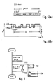
- FIG. 1a An apparatus of the invention in simplified form is shown in Figure 1a in which an internal combustion engine 1 has a parameter thereof which is to be sensed or corrected.
- the parameter to be sensed or corrected has a noise signal component thereon which makes detection of a small incremental change of the parameter impossible to detect in the prior art.
- a psuedo random signal is generated which is herein termed a search signal and which may be an M series signal known per se , briefly described later herein but described more fully in "CORRELATION FUNCTION AND SPECTRUM - Measurement and Application thereof", edited by Takashi Isobe, published by Tokyo-Daigaku-Shuppansha.
- the search signal is generated by a generator 2 which outputs the search signal to be added by adder 7 into the parameter to be sensed or corrected, e.g. fuel injection time and/or ignition timing.
- the parameter with the search signal added thereto and, of course including the noise signal component, is applied as one input to a correlator 3, the other input of the correlator 3 being provided from the search signal generator 2.
- the correlator 3 thus is able to detect the combined engine parameter and the search signal and to correlate the search signal so that, effectively, the noise and the search signal are removed in the correlation process.
- the output of the correlator is applied to an integrator 4 which acts as a digital filter, the output of the intergrator 4 providing a correction factor ⁇ 1.
- the correction factor ⁇ 1 as shown in Figure 1(b) is applied to a unit 5 for correcting or diagnosing sensor and/or engine parameters.
- the output of the unit 5 may also be applied to an alarm 6 shown in broken lines.
- the speed, i.e. number of revolutions N, of an internal combustion engine is detected by a crank angle sensor 12, and air quantity Q a sucked into a cylinder of the engine is detected by an air flow sensor 14.
- the crank angle sensor 12 also supplies reference signals REF shown in Figure 9(a) and position indicating signals at, for example, 1° intervals as shown in Figure 9(b).
- the signals REF are generated for example at 110° before top dead center (TDC) and the REF signals and POS signals are supplied to a control unit (not shown in Figure 2).
- An air fuel ratio compensator 18 receives signals representative of load L and engine revolutions N (and optionally the output of an air fuel ratio sensor O2) and supplies a signal representative thereof to one input of a control unit 20, shown diagrammatically as a multiplier.
- the other input of the unit 20 is a standard injection timing signal T p derived by unit 19 that is proportional to load L.
- the unit 20 provides a fuel injection time signal T i for a cylinder of the internal combustion engine, the signal being provided to a fuel injector 22.
- the control unit 20 provides as an output the actual fuel injection time T i either by adding the injection time calculated by the air/fuel ratio compensator 18 to the standard fuel injection time T p (as shown in Figure 2) or by multiplying the standard time T p by a correction coefficient (not shown).
- the fuel injector 12 injects the fuel into the cylinder of the engine for the injection period T i .
- An ignition timing control unit 24 generates a basic ignition advance angle ⁇ advB which is determined in response to the number of revolutions of the internal combustion engine and load and read from a map held in ROM in the unit 14.
- a pseudo random signal having varying mark ( ⁇ )/space ratio which repeats after time period n ⁇ where n is an integer is used as a correction signal and the pseudo random signal, search signal is an M series signal generated by a generator 26 located within a single-chip micro computer 50.
- the M series signal x ⁇ (t) is based on the data shown in Figfure 6(a) and 6(b) described later herein.
- the M series signal has a signal component of ignition advance angle ⁇ advM .
- a parameter y(t) representative of the number of engine revolutions is combined with the M series signal, the resultant is detected and the M series signal correlated by unit 28.
- the output of the correlator ⁇ is applied to an integral control 30 and to a proportional control 32.
- the output of the proportional control 32, k ⁇ is multiplied in unit 34 to provide a signal ⁇ advPI which is applied to an adder 36.
- the output of adder 36 is signal ⁇ advP which is applied to one input of another adder 42 having as another input the output ⁇ advI from unit 30.
- the resultant output from adder 42 is ⁇ adv O ⁇ which is the optimised signal component of the ignition advance angle and given by x ⁇ 1 (t).
- the output from adder 42 is applied to another adder 44 which receives as another input the output ⁇ advM from the M series signal generator 26.
- the combined signals are applied to another adder 46 having input x ⁇ O (t) which is the basic ignition advance angle ⁇ advB to provide an output x(t) which is the ignition timing signal ⁇ ig applied to the ignition coil 48.
- a mutual correlation function is performed of the M series signal x ⁇ (t) and engine RPM N represented by y (t), the correlation function is integrated and the output ⁇ is a phase integral which is itself integrated and after combining with the M series signal in adder 44 so the signal is overlapped onto the basic ignition advance angle ⁇ advB denoted by x ⁇ O (t) and the ignition timing supplied to the coil 48.
- the M series signal as shown in Figure 3(a) has an amplitude a, a minumum pulse width ⁇ , period n ⁇ where n is the maximum sequence and in the present embodiment equals 31. However n equals 5 and 15 are integers found by trial and experiment for different engine types which may also be used.
- the M series signal x ⁇ (t) is generated with the amplitude a in a range causing a change in the number of engine revolutions that will not be perceived by a driver of the vehicle and the M series signal is overlapped on the ignition timing signal ⁇ ig.
- the mutual correlation function and the phase shift integral of this M series signal x ⁇ (t) versus the number of revolutions y (t) of the engine are calculated to determine output torque gradient ⁇ .
- the output torque gradient is integrated and combined on the original engine timing signal. In such a manner the ignition timing is controlled so as to be maintained at the optimum position without the necessity as in the prior art of excessively fluctuating the engine speed of revolution so that jerking of the vehicle is not noted by a driver with use of this invention.
- RPM y (t) may be considered as the DC component about which the engine RPM ⁇ (t) fluctuates.
- x(t) x ⁇ (t) + x (t) (1)
- y(t) ⁇ (t) + y (t) (2)
- the characteristics shown in Figure 3(c) of torque (which is equivalent to engine speed of rotation) against ignition timing ( ⁇ ig) has a characteristic which is initially positive and then negative.
- the optimum ignition angle ⁇ optimum is taken when the slope of the torque/ignition angle curve is zero. The slope of the curve is thus constantly monitored for the optimum angle at which torque is maximum.
- the impulse response g( ⁇ ) is given by equation (10) below using the mutual correlation function ⁇ x ⁇ ( ⁇ ) between x ⁇ (t) and ⁇ (t).
- g( ⁇ ) ⁇ x ⁇ ( ⁇ ) / ⁇ x ⁇ x ⁇ (o) (10) where, ⁇ x ⁇ x ⁇ (O) corresponds to the integrated value of self correlation function ⁇ x ⁇ x ⁇ , and is given by the following equation;
- the mutual correlation function ⁇ x ⁇ ( ⁇ ) is transformed as shown below using equation (2);
- y(t) is composed of fluctuating components due to the influence of M-series signal x ⁇ (t), and the DC component from x(t) ; however, it is difficult to separate and detect these components so that a directly obtainable function is a mutual correlation function ⁇ x ⁇ y shown by the following equation.
- ⁇ x ⁇ y 1 n ⁇ ⁇ n ⁇ o y(t) ⁇ x ⁇ (t- ⁇ )dt (13′)
- the value of ⁇ x ⁇ y ( ⁇ ) approximates to the value of ⁇ x ⁇ y( ⁇ ) if the value of large because the value of ⁇ x ⁇ y ( ⁇ ) is no longer influenced by x ⁇ (t).
- ⁇ x ⁇ y ( ⁇ ) can be approximately substituted by the average value of ⁇ x ⁇ y( ⁇ ) in the interval between ⁇ 1 and ⁇ 2.
- ⁇ 1 and ⁇ 2 are bias compensation terms and they are selected to have values close to n . ⁇ .
- ⁇ S is the starting time of the integration in consideration of the leading adge of the impulse response due to the pseudo-white noise of the M-series signal.
- ⁇ L is the ending time of the integration inverval for impulse response integration. This is set in advance, in accordance with the impulse response characteristics.
- This output torque slope ⁇ corresponds to the change in number of revolutions of the internal combustion engine, when the ignition timing is changed by a unit quantity by the search signal, and this is called the output torque gradient
- the optimum ignition timing is more smoothly achieved by overlapping the further integration of the above-mentioned output torque gradient ⁇ on the ignition timing signal ⁇ ig.
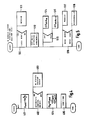
- a basic ignition advance angle ⁇ advB which is a function of engine revolutions N and load (Q a /N) is determined in step 401.
- an M series ignition advance angle setting routine 403 is set to start, the M series routine being described more fully with reference to Figure 5.
- processing step 404 is shown schematically in Figure 2 as the summation of inputs of adders 44 and 46.
- the power is supplied to the ignition coil 48.
- the M series signal is shown in Figure 6(b) having a abscissa of time against ignition angle ⁇ ig and the mean amplitude of the M series signal is at ⁇ advB with the amplitude of the M series signal being represented by ⁇ advM .
- the M series signal component ignition advance angle routine is shown in detail.
- the M series signals are generated by successive readout of bit data from previously set M series signal x ⁇ (t) data.
- the data is read out of a register, schematically shown in Figure 6(a) having register positions 2 O to 2 n-1 and having a total count herein shown as 2 MCNT .
- the first run of data is determined in step 510 and if affirmative a counter MCNT is cleared at step 511. Retrievals for the M series signal bit data are then performed at step 512, then, using equation:- where a is the amplitude of the M series signal.
- the M series signal component ignition advance angle ⁇ advM is thus generated at steps 513, 514 and 515.
- the counter/register MCNT is updated in accordance with following: where, n-1 : period of M-series signal.
- FIG 7 is a flow diagram of the slope of the torque/ignition timing slope detection and correlation performed by unit 28.
- the M series signal x ⁇ (t) is sampled together with the number of revolutions of the internal combustion engine N at step 701 and both sets of data are input and memorised in the micro computer.
- the output torque gradient ⁇ is computed at step 704 in accordance with equations 14 and 15.
- m is an interger as will be described later herein.
- step 702 it is determined whether the data m and n is stored in memory and if it is then the calculation for ⁇ can be performed.
- the equation (19a) evaluated at step 801 is the output of unit 30 shown in Figure 2.
- the integration control gain coefficient G is a coefficient representing the relationship between an output torque gradient and an optmised ignition timing and is set in accordance with individual internal combustion engines.
- the optimised signal component ignition advance angle ⁇ adv O ⁇ is preferably formed in two steps in conformity with the immediate factor of Proportional output ⁇ and in accordance with a phase delay time L.
- Figure 9 shows the relative timings on which the respective calculation routines operate.
- Figure 9(a) shows the ignition timing setting routine to start with the timing of reference signals REF which are generated for each cylinder.
- the reference signals are generated at 110° before top dead centre (TDC) of each cylinder.
- TDC top dead centre
- reference signals REF are generated every 120°, that is, three pulses are generated per revolution, i.e. two revolutions are performed in one cycle so that six reference signals REF are generated during one cycle.
- Reference signals R1 to R3 correspond to the first cylinder to the third cylinder only and the period T ref of the reference signal REF becomes smaller as the number of engine revolutions increases.
- the position signals are shown in Figure 9(b) and are generated at 1° intervals at rotation of the crank shaft.
- the ignition coil current is controlled in response to the calculated results of this routine, and an ignition pulse is generated at the previously determined ignition timing.
- the flow time for the ignition coil current is determined upon conditions such as output voltage of the battery and number of revolutions of the internal combustion engine, and the starting time for the current T S is adjusted to a value computed by the ignition advance angle setting routine, as shown in Figure 9(d) and 9(e). For example, if an M series signal such as the one shown in Figure 9(c) is produced, and the ignition advance angle is changed with ⁇ a then the starting time for the current T S is modified with ⁇ a resulting in an adjustment T f of the ignition coil current and the ignition pulse shown in Figure 9(f) is generated at time T f .
- an optimised control routine starts at an optimised control timing which is determined by dividing the reference signal RET into 1/m, where m is predetermined integer.
- the timing period T ref /m at which the optimised control routine is set to start is proportional to the reference signal REF, the number of revolutions of the internal combustion engine is detected by measuring the interval of the optmised control timing operation. Since the detected number of revolutions has the same value within the period from one optimised control timing pulse generation to the next timing pulse generation (such as an interval T shown in Figure 9(g)), the optimised control routine is set to start at anywhere within the interval T.
- any number from 1 to 5 can be selected as the value for integer m, however, even if a larger number of m is selected, the detected number of revolutions is virtually the same at low speed running and such a larger number will only result in increasing a burden on the micro-computer. In practice, values such as 1 or 2 are adequate.
- both routines are not always sychronised and, moreover, priority may be given with regard to either of the processings.
- the optimised control routine may be run on a time basis; further if there is insufficient processing time, the processing of the ignition advance angle setting routine may be given priority so that the control can be made certain.
- the processing may be separately executed during the measuring period for obtaining an output torque gradient in every period of the M series signal T ref .N and during the control output period so as to control the ignition timing at an optimised value.
- the minimum pulse widths ⁇ of the M series signal is an integer as large as the number of combustion strokes of the internal combustion engine.
- a reference signal REF is generated at every 120°, that is to say, six signals for every 2 revolutions, and the minimum pulse width ⁇ is set at an integer as large as the period T ref of the reference signal REF.
- the minimum pulse width ⁇ is set at the same magnitude as the number of combustion strokes, then the result is as shown in Figure 10(a), and if the minimum pulse width is set to be six times as large as the number of combustion strokes then the result is as shown in Figure 10(b).
- the minimum pulse width is set at the number of combustion strokes, all the cylinders are given the same ignition timing signal. If the minimum pulse width ⁇ is set as a magnitude less than the number of combustion strokes it may happen that two or more ignition timing commands are given simultaneously to one cylinder or the M series signal falls into disorder. This minimum pulse width is set at a small magnitude with an increasing number of engine revolutions.
- Equation (20) In the calculations for the indicial (step) response ⁇ , the equation is transformed into the form of equation (20) below by exchanging the time integral in the mutual correlation function with the integral of the above phase ⁇ :- where Z : power of auto correlation of M series signal, i.e. area of triangle having base 2 ⁇ of Figure 3(b), and X(t) is a function corresponding to the intergration by parts of the signal x ⁇ (t) represented by equation (21) below, and depends on x ⁇ (t) only, with no relation to the response signal y(t) of an internal combustion engine control system.
- this correlation signal X(t) needs to be stored in a memory, provided the initial value X(0) is first determined and the difference is calculated at each timing.
- T S a sampling period
- the micro processor 150 in this embodiment has an M series signal generator 26 supplying signal x ⁇ (t) to an adder 44 added and to a correlation signal generator 128.
- the output from the correlation signal generator is signal X(t) which is supplied as one input to a multiplier 129, the other input of the multiplying being signal y(t) representative of the engine rotational speed.
- Output from multiplier 129 is fed to a time integrater 130 the output of which is signal ⁇ supplied to an integral control unit 131.
- Output from unit 131 is signal ⁇ adv O ⁇ which is supplied to another input to the adder 44.
- the remaining part of the circuit shown in Figure 11 is similar to that shown in Figure 2.
- the correlation function X(t) is calculated in accordance with equation (28) sychronously with the M series signal and is stored in a memory.
- the optimised control programme for execution by a micro computer is shown in the flow diagram of Figure 12.
- a data input 1201 the number of revolutions of the internal combustion engine y is sampled and the correlation signal is generated at step 1202 to provide X(t) as shown in equation (21).
- the optimimum signal component ignition advance angle ⁇ adv O ⁇ is determined using equation (19) (c) at step 1205.
- the output torque gradient ⁇ is reset at step 1206 to prepare for the next cycle calculation.
- the correlation function is calculated in a step-by-step method. Therefore there is no need to store the M series data signals x(t) and the number of revolutions of the internal combustion engine y over one cycle of the M series signal, thus the memory capacity required is greatly reduced. Because, the integral by phase ⁇ is executed in advance, real time execution is limits to the time integral only and the time required for calculations is therefore greatly reduced.
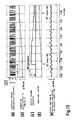
- Figure 13 shows the results of some simulations of the present invention when applied to a six cylinder internal combustion engine.
- Figure 13(a) shows M series signal changes of plus or minus 1° which are overlapped onto an ignition timing signal and the number of engine revolutions changed with the M series signal by approximately 50 RPM as shown by Figure 13(b).
- a mutual correlation function between the detected number of revolutions of the engine was calculated for each period of the M series signal to provide an output torque gradient as shown in Figure 13(c) and as a result of the overlap of the integrated value of the output torque gradient on the ignition timing signal, so the ignition timing moved from its initial position of 20° before TDC to a new position of 28° before TDC (the optimum position) in about 4 seconds as shown by Figure 13(d).
- the acceleration of the vehicle in the direction of travel was within ⁇ 0.03 G, which is in a range that would not be perceived by a driver as shown in Figure 13(e).
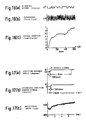
- Figure 17 shows the test results using an actual car, where the M series signal overlapped for 620 msec, as shown in Figure 17(a).
- the ignition timing was corrected by about 10° from 23° to 30° as shown in Figure 17(a) and 17(b) and the delay time L was 140 msec.
- the revolution speed exhibited a hill climbing characteristic as shown in Figure 17(c) and the ignition timing moved to the optimum position.
- the invention renders ignition timing control of an internal combustion engine smoother, providing very small velocity changes for change in ignition timing.
- the subject invention has been described in relation to modifying the ignition timing, the invention is not intended to be so restricted.
- the M series signal could be used to incrementally modify fuel injection pulse width or could be used to detect an output from an O2 sensor to control fuel injection to thereby provide a cleaner exhaust gas.
Landscapes
- Engineering & Computer Science (AREA)
- Chemical & Material Sciences (AREA)
- Combustion & Propulsion (AREA)
- Mechanical Engineering (AREA)
- General Engineering & Computer Science (AREA)
- Theoretical Computer Science (AREA)
- Signal Processing (AREA)
- Electrical Control Of Ignition Timing (AREA)
- Combined Controls Of Internal Combustion Engines (AREA)
Applications Claiming Priority (2)
| Application Number | Priority Date | Filing Date | Title |
|---|---|---|---|
| JP1056487A JPH0689731B2 (ja) | 1989-03-10 | 1989-03-10 | 内燃機関の点火時期制御方法および装置 |
| JP56487/89 | 1989-03-10 |
Publications (3)
| Publication Number | Publication Date |
|---|---|
| EP0387100A2 true EP0387100A2 (de) | 1990-09-12 |
| EP0387100A3 EP0387100A3 (de) | 1993-09-15 |
| EP0387100B1 EP0387100B1 (de) | 1997-10-08 |
Family
ID=13028459
Family Applications (1)
| Application Number | Title | Priority Date | Filing Date |
|---|---|---|---|
| EP90302585A Expired - Lifetime EP0387100B1 (de) | 1989-03-10 | 1990-03-12 | Verfahren und Vorrichtung zur Steuerung des Zündzeitpunktes bei einer inneren Brennkraftmaschine |
Country Status (5)
| Country | Link |
|---|---|
| US (1) | US5144560A (de) |
| EP (1) | EP0387100B1 (de) |
| JP (1) | JPH0689731B2 (de) |
| KR (1) | KR900014740A (de) |
| DE (1) | DE69031546T2 (de) |
Cited By (4)
| Publication number | Priority date | Publication date | Assignee | Title |
|---|---|---|---|---|
| WO1997018467A1 (en) * | 1995-11-16 | 1997-05-22 | Aromascan Plc | Sensor interrogation |
| EP1985832A1 (de) | 2007-04-25 | 2008-10-29 | HONDA MOTOR CO., Ltd. | Steuerparameter für Suche |
| CN103912432A (zh) * | 2013-01-07 | 2014-07-09 | 通用汽车环球科技运作有限责任公司 | 随机调节发动机点火频率来减少振动的系统和方法 |
| DE102017223662A1 (de) * | 2017-12-22 | 2019-06-27 | Volkswagen Aktiengesellschaft | Vorrichtung und Verfahren zur Diagnose variabler Ventilbetriebsstellungen |
Families Citing this family (14)
| Publication number | Priority date | Publication date | Assignee | Title |
|---|---|---|---|---|
| JPH03210065A (ja) * | 1990-01-12 | 1991-09-13 | Nissan Motor Co Ltd | エンジンのノッキング制御装置 |
| JP3303981B2 (ja) * | 1991-12-20 | 2002-07-22 | 株式会社日立製作所 | エンジン排気ガス浄化装置の診断装置 |
| JPH06294371A (ja) * | 1993-04-12 | 1994-10-21 | Mitsubishi Electric Corp | 内燃機関点火装置 |
| US5559705A (en) * | 1995-02-03 | 1996-09-24 | Motorola, Inc. | Adaptive profile correction for rotating position encoders in reciprocating engines |
| AU9295298A (en) * | 1997-11-03 | 1999-05-24 | Engelhard Corporation | Apparatus and method for diagnosis of catalyst performance |
| US6026639A (en) * | 1997-11-03 | 2000-02-22 | Engelhard Corporation | Apparatus and method for diagnosis of catalyst performance |
| DE10100873A1 (de) * | 2001-01-11 | 2002-08-08 | Siemens Ag | Verfahren zum Einschalten einer induktiven Last |
| US6834540B2 (en) * | 2002-09-20 | 2004-12-28 | Spx Corporation | Engine cylinder event fill-in (phylinder) |
| JP4364777B2 (ja) * | 2004-12-02 | 2009-11-18 | 本田技研工業株式会社 | 内燃機関の空燃比制御装置 |
| JP4486923B2 (ja) * | 2005-12-19 | 2010-06-23 | 本田技研工業株式会社 | 制御装置 |
| US20090118984A1 (en) * | 2007-11-05 | 2009-05-07 | Xiuyu Che | Ignition Method with Energy Conservation and Environmental Protection for Gasoline Engine |
| DE102013208721A1 (de) * | 2012-06-12 | 2013-12-12 | Ford Global Technologies, Llc | Verfahren und Vorrichtung zum Betreiben eines Verbrennungsmotors |
| JP7087609B2 (ja) * | 2018-04-11 | 2022-06-21 | トヨタ自動車株式会社 | エンジン制御装置 |
| DE102019113807B4 (de) * | 2019-05-23 | 2024-01-04 | Volkswagen Aktiengesellschaft | Verfahren zum Betreiben eines Verbrennungsmotors |
Family Cites Families (11)
| Publication number | Priority date | Publication date | Assignee | Title |
|---|---|---|---|---|
| JPS5388426A (en) * | 1977-01-17 | 1978-08-03 | Hitachi Ltd | Ignition timing control system for internal combustion engine |
| FR2381919A1 (fr) * | 1977-02-25 | 1978-09-22 | Anvar | Dispositif numerique de controle d'avance pour moteurs a combustion interne |
| DE2739508C2 (de) * | 1977-09-02 | 1986-01-16 | Robert Bosch Gmbh, 7000 Stuttgart | Vorrichtung zur Extremwertregelung bei Brennkraftmaschinen |
| US4375668A (en) * | 1978-05-08 | 1983-03-01 | The Bendix Corporation | Timing optimization control |
| US4379333A (en) * | 1979-08-29 | 1983-04-05 | Nippondenso Co., Ltd. | Method and system for operating a power-producing machine at maximum torque under varying operating conditions |
| JPS5768537A (en) * | 1980-10-17 | 1982-04-26 | Nissan Motor Co Ltd | Fuel controller |
| EP0235418B1 (de) * | 1986-03-03 | 1990-08-22 | Optimizer Control Corporation | System und Verfahren zum Optimieren der Arbeitsweise einer Kraftmaschine |
| JPS61244856A (ja) * | 1985-04-24 | 1986-10-31 | Nippon Denso Co Ltd | エンジンの信号処理装置 |
| DE3642771A1 (de) * | 1986-12-15 | 1988-06-23 | Kuipers Ulrich | Verfahren und vorrichtung zur messung der messgroesse eines messobjekts |
| GB8700759D0 (en) * | 1987-01-14 | 1987-02-18 | Lucas Ind Plc | Adaptive control system |
| JP2502385B2 (ja) * | 1989-09-06 | 1996-05-29 | 株式会社日立製作所 | 内燃機関の燃料量及び点火時期制御方法および装置 |
-
1989
- 1989-03-10 JP JP1056487A patent/JPH0689731B2/ja not_active Expired - Lifetime
-
1990
- 1990-03-06 KR KR1019900002935A patent/KR900014740A/ko not_active Withdrawn
- 1990-03-12 US US07/492,596 patent/US5144560A/en not_active Expired - Fee Related
- 1990-03-12 EP EP90302585A patent/EP0387100B1/de not_active Expired - Lifetime
- 1990-03-12 DE DE69031546T patent/DE69031546T2/de not_active Expired - Fee Related
Cited By (6)
| Publication number | Priority date | Publication date | Assignee | Title |
|---|---|---|---|---|
| WO1997018467A1 (en) * | 1995-11-16 | 1997-05-22 | Aromascan Plc | Sensor interrogation |
| US6236951B1 (en) | 1995-11-16 | 2001-05-22 | Osmetech Plc | Sensor interrogation |
| EP1985832A1 (de) | 2007-04-25 | 2008-10-29 | HONDA MOTOR CO., Ltd. | Steuerparameter für Suche |
| CN103912432A (zh) * | 2013-01-07 | 2014-07-09 | 通用汽车环球科技运作有限责任公司 | 随机调节发动机点火频率来减少振动的系统和方法 |
| CN103912432B (zh) * | 2013-01-07 | 2016-08-24 | 通用汽车环球科技运作有限责任公司 | 随机调节发动机点火频率来减少振动的系统和方法 |
| DE102017223662A1 (de) * | 2017-12-22 | 2019-06-27 | Volkswagen Aktiengesellschaft | Vorrichtung und Verfahren zur Diagnose variabler Ventilbetriebsstellungen |
Also Published As
| Publication number | Publication date |
|---|---|
| EP0387100A3 (de) | 1993-09-15 |
| DE69031546D1 (de) | 1997-11-13 |
| KR900014740A (ko) | 1990-10-24 |
| EP0387100B1 (de) | 1997-10-08 |
| JPH0689731B2 (ja) | 1994-11-14 |
| DE69031546T2 (de) | 1998-04-02 |
| US5144560A (en) | 1992-09-01 |
| JPH02238172A (ja) | 1990-09-20 |
Similar Documents
| Publication | Publication Date | Title |
|---|---|---|
| EP0387100A2 (de) | Verfahren und Vorrichtung zur Steuerung des Zündzeitpunktes bei einer inneren Brennkraftmaschine | |
| EP0589517A1 (de) | Verfahren zur Vorausbestimmung des Luftstroms in einem Zylinder | |
| EP0185552B1 (de) | Vorrichtung zum Steuern des Betriebs eines Innenverbrennungsmotors | |
| EP0070724B1 (de) | Verfahren zur Regelung der Leistung einer funkengezündeten Brennkraftmaschine | |
| JPH0528365Y2 (de) | ||
| US4577718A (en) | Apparatus for controlling the speed of a vehicle with internal combustion engine | |
| US4789939A (en) | Adaptive air fuel control using hydrocarbon variability feedback | |
| EP0416856B1 (de) | Diagnosesystem und optimales Steuerungssystem für einen Innenverbrennungsmotor | |
| EP0297747B1 (de) | Adaptives Steuerungssystem für eine Brennkraftmaschine | |
| EP0345814B1 (de) | Elektrisches Steuergerät für Kraftfahrzeug und Kompensationsverfahren der Zeitverzögerung von Messdaten | |
| EP0309103B1 (de) | Anpassungsfähiges Steuersystem für eine innere Brennkraftmaschine | |
| US4971011A (en) | Air and fuel control system for internal combustion engine | |
| EP0184626A2 (de) | Steuerverfahren für einen Motor mit Kraftstoffeinspritzung | |
| US5129379A (en) | Diagnosis system and optimum control system for internal combustion engine | |
| US4930482A (en) | Fuel control apparatus for engines | |
| EP0314081B1 (de) | Steuerungssystem für Brennkraftmaschine mit verbesserten Steuerungskenngrössen während des Übergangsbetriebs | |
| KR19990062660A (ko) | 엔진 제어 장치 | |
| US4633838A (en) | Method and system for controlling internal-combustion engine | |
| US6302083B1 (en) | Method for cylinder equalization in an internal combustion engine operating by direct injection | |
| JPH02130240A (ja) | 内燃機関の空燃比制御装置 | |
| EP0332119B1 (de) | Elektronisches Motor-Steuerungsverfahren | |
| JP3469254B2 (ja) | 内燃機関の電子燃料供給量制御装置 | |
| EP0234715B1 (de) | Lernendes Steuerungssystem für Brennkraftmaschine | |
| JPH10184429A (ja) | エンジン制御方式 | |
| EP0070732B1 (de) | Verfahren zur Darstellung eines Energie-Ausgangssignals |
Legal Events
| Date | Code | Title | Description |
|---|---|---|---|
| PUAI | Public reference made under article 153(3) epc to a published international application that has entered the european phase |
Free format text: ORIGINAL CODE: 0009012 |
|
| 17P | Request for examination filed |
Effective date: 19900406 |
|
| AK | Designated contracting states |
Kind code of ref document: A2 Designated state(s): DE GB |
|
| PUAL | Search report despatched |
Free format text: ORIGINAL CODE: 0009013 |
|
| AK | Designated contracting states |
Kind code of ref document: A3 Designated state(s): DE GB |
|
| 17Q | First examination report despatched |
Effective date: 19950626 |
|
| GRAG | Despatch of communication of intention to grant |
Free format text: ORIGINAL CODE: EPIDOS AGRA |
|
| GRAH | Despatch of communication of intention to grant a patent |
Free format text: ORIGINAL CODE: EPIDOS IGRA |
|
| GRAH | Despatch of communication of intention to grant a patent |
Free format text: ORIGINAL CODE: EPIDOS IGRA |
|
| GRAA | (expected) grant |
Free format text: ORIGINAL CODE: 0009210 |
|
| AK | Designated contracting states |
Kind code of ref document: B1 Designated state(s): DE GB |
|
| REF | Corresponds to: |
Ref document number: 69031546 Country of ref document: DE Date of ref document: 19971113 |
|
| PLBE | No opposition filed within time limit |
Free format text: ORIGINAL CODE: 0009261 |
|
| STAA | Information on the status of an ep patent application or granted ep patent |
Free format text: STATUS: NO OPPOSITION FILED WITHIN TIME LIMIT |
|
| 26N | No opposition filed | ||
| REG | Reference to a national code |
Ref country code: GB Ref legal event code: IF02 |
|
| PGFP | Annual fee paid to national office [announced via postgrant information from national office to epo] |
Ref country code: GB Payment date: 20020301 Year of fee payment: 13 |
|
| PGFP | Annual fee paid to national office [announced via postgrant information from national office to epo] |
Ref country code: DE Payment date: 20020328 Year of fee payment: 13 |
|
| PG25 | Lapsed in a contracting state [announced via postgrant information from national office to epo] |
Ref country code: GB Free format text: LAPSE BECAUSE OF NON-PAYMENT OF DUE FEES Effective date: 20030312 |
|
| PG25 | Lapsed in a contracting state [announced via postgrant information from national office to epo] |
Ref country code: DE Free format text: LAPSE BECAUSE OF NON-PAYMENT OF DUE FEES Effective date: 20031001 |
|
| GBPC | Gb: european patent ceased through non-payment of renewal fee |
Effective date: 20030312 |