EP0387632A2 - Dispositif de coupure et d'enroulage pour rubans - Google Patents
Dispositif de coupure et d'enroulage pour rubans Download PDFInfo
- Publication number
- EP0387632A2 EP0387632A2 EP90104077A EP90104077A EP0387632A2 EP 0387632 A2 EP0387632 A2 EP 0387632A2 EP 90104077 A EP90104077 A EP 90104077A EP 90104077 A EP90104077 A EP 90104077A EP 0387632 A2 EP0387632 A2 EP 0387632A2
- Authority
- EP
- European Patent Office
- Prior art keywords
- winding
- film
- cutting
- strips
- web
- Prior art date
- Legal status (The legal status is an assumption and is not a legal conclusion. Google has not performed a legal analysis and makes no representation as to the accuracy of the status listed.)
- Granted
Links
Images
Classifications
-
- B—PERFORMING OPERATIONS; TRANSPORTING
- B65—CONVEYING; PACKING; STORING; HANDLING THIN OR FILAMENTARY MATERIAL
- B65H—HANDLING THIN OR FILAMENTARY MATERIAL, e.g. SHEETS, WEBS, CABLES
- B65H19/00—Changing the web roll
- B65H19/22—Changing the web roll in winding mechanisms or in connection with winding operations
-
- B—PERFORMING OPERATIONS; TRANSPORTING
- B65—CONVEYING; PACKING; STORING; HANDLING THIN OR FILAMENTARY MATERIAL
- B65H—HANDLING THIN OR FILAMENTARY MATERIAL, e.g. SHEETS, WEBS, CABLES
- B65H2301/00—Handling processes for sheets or webs
- B65H2301/50—Auxiliary process performed during handling process
- B65H2301/51—Modifying a characteristic of handled material
- B65H2301/513—Modifying electric properties
- B65H2301/5133—Removing electrostatic charge
Definitions
- the invention relates to a cutting and winding device for film strips, in which, following a slitting station for cutting film strips from a web, the film strips arranged essentially in a horizontal row are guided to a winding or winding unit. It also relates to a method for changing the spool or winding core when winding up the film strips.
- a continuous film web of constant width is cut into individual film strips. This is done with the help of a row of stationary separating knives arranged perpendicular to the web running direction, which are equally spaced from one another and protrude into the web with their cutting edges directed against the web movement.
- the finished film strips are then individually wound onto spools or flangeless winding cores on a winding unit.
- the individual winding units can be arranged in a row one behind the other or next to one another in the running direction of the film strips, or if there are a large number of film strips to be wound up, several rows of winding units can also be arranged one above the other in tiers.
- DE 34 14 636 describes a method for changing bobbins, in which the amount of waste which is to be reduced when winding up several rows of winding units which are arranged one behind the other.
- a cutting and winding device is known, in which the separate film strips are wound onto cores which are firmly connected to a winding shaft, and four winding shafts are present within a winding star, which are axially displaceable and one denaturing and one Assembly device can be supplied, which simultaneously takes care of the removal of one winding shaft from winding cores and the loading of another shaft with new winding cores.
- a reel cutting and winding machine for film strips is known, in which, following a longitudinal cutting station for cutting web strips from a web, a separation station is provided for separating adjacent web strips into separate winding axes, with alignment combs in the longitudinal grooves of each winding axis radial alignment edges are adjustably arranged, which position the winding tubes.
- a corresponding device is known in which, following a slitting station for cutting strips of film from a web, the films on individual Winding cores are guided and each winding core is assigned a drive roller resting on the circumference of the winding.
- winding devices for cut web strips are known, in which the strips are guided over a so-called spreading comb, which are pins which deflect the film strips in different directions and the strips are wound up with a device according to DE 23 65 606 mentioned above.
- this requires extensive effort when changing the bobbin as soon as the full winding circumference is reached.
- a 65 cm wide magnetic tape web is cut lengthways into 3.81 mm wide strips, which are wound on winding cores, around 170 tape windings have to be glued at the end and removed from the winding axis, after which these winding axes are newly fitted with cores, on which then the beginnings of the film strips must be attached.
- This can mean a considerable changeover time, which is about as long as the winding time.
- a further work step arises from the fact that the finished tape rolls may have to be provided with intermediate layers for transport and stacked on top of each other in larger containers.
- the device described above takes up a considerable amount of space. Therefore, the task was to find a winding device of the generic type mentioned above, which - is compact - Significantly reduced changeover times when changing the winding - already delivers ready-to-ship packages.
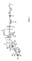
- Figure 1 shows schematically the side view of a preferred embodiment of the device according to the invention.
- the film web (1) coming from a casting or extrusion device (not shown) is fed in the direction of the arrow via a cross cutting device (2) to be described further below, and subsequently via a loop puller (8) to compensate for the web voltage fluctuations.
- the web is subsequently cut lengthwise into narrow strips (4) by means of a separating knife arrangement (9), the axis of which is arranged perpendicular to the direction of the film web, or a reel cutter.
- a separating knife arrangement 9
- Such arrangements are known from numerous publications, for example from DE 24 05 849 or DE 37 01 716 from the applicant, where in particular arrangements for cutting magnetic tape webs in film strips are described.
- the cut strips are passed between a pivotable pressure roller (6), the width of which is at least as large as the entire width of the film web, and a guide suction comb (3).
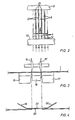
- the suction comb consists (FIG. 2) of a number of vertically arranged segments (5), the number and width of which corresponds to the number and width of the film strips and which can be subjected to negative pressure. The segments are spaced from each other. The suction comb is laterally pivotable in the film running direction.
- the winding of the film strips (4) is accomplished by a rotatable winding device (10) consisting of at least two arms (12, 12 '), at the free ends of which a drivable shaft (13, 13') is located as the winding axis.
- a rotatable winding device consisting of at least two arms (12, 12 '), at the free ends of which a drivable shaft (13, 13') is located as the winding axis.
- flange coils or flangeless winding cores 14, 14 '
- Flange-less winding cores and particularly preferably stackable winding cores according to DE 24 48 853 are preferred for winding according to the device according to the invention, which are stacked on top of one another so that they are tensioned on a winding shaft in such a way that the windings or the winding surfaces lie practically spaced apart.
- the cross-cutting device (2) already mentioned is used to produce a defined strip length, one strip length being provided with the following one with a specific adhesive point.
- this device consists in a preferred embodiment of a three-part cutting table. This has two fixed parallel support rails (16, 17) transverse to the film running direction and a narrow movable support rail (18) arranged between them. Between the two columns of the rails (16, 17) and the vertically displaceable rail (18), two cutting wheels (15, 15 ') or cutting knife blades for cross-cutting the web (1) can be immersed.
- adhesive tape (22) for connecting the two separate web pieces a tape provided with an adhesive surface is preferably used, the two lateral ends (19, 19 ') of which are turned away from the adhesive surface (20), are bent at an obtuse angle and are free of adhesive (FIG. 4).
- the cutting table can consist of only two support rails, with one there between the gap, a rail being horizontally displaced after the separation of the web by the width of the rail (18) and the adhesive connection subsequently being produced.
- the adhesive tape (22) can also have only one glue-free, bent end.
- the full tape windings (23) wound on the winding cores (14) are each with an adhesive tape (22) on the outer circumference of the tape winding.
- the roller (6) is then pivoted onto the suction comb (3), the segments (5) of which are subjected to negative pressure, so that they suck in the film strips (4).
- the rotatable roller (6) is wetted on its cylindrical surface (24) with a liquid, for example water, for moistening the underside of the film web strips.
- the cutting wheel (7) is lowered onto the film level and the film strips (4) are cut off transversely to the web direction. This leaves from the glue point (22) to the end of the film a film residue (4 ') of 5 to 20 cm, from the interface to the beginning of the suction comb (3) about 5 to 10 cm.
- the winding device (10) rotates through 180 °, so that now on the winding shaft (13 ') already unwound cores (14') are located adjacent to the suction comb.
- the roller (6) is pivoted away from the suction comb, whereupon the latter with the held strip ends (4) the winding shaft (13 ') with the cores (14') is pivoted to a small distance, so that it reaches the position shown in dashed lines in Figure 1.
- On the winding cores (14 ') now come the moistened undersides of the ends of the cut strips (4) to lie.
- the empty cores (14 ') may have been moistened beforehand by an appropriate device.
- the outer periphery of the intermediate layer foils (21) provided between the winding cores can dip into the open gaps (25) between the segments (5) of the guide suction comb (3). This can be facilitated by the winding shaft (13 ') starting up briefly, for example, and the intermediate layers being tightened as a result of centrifugal force.
- the winding shaft (13 ') is slowly driven then faster and the winding process begins, while at the same time the negative pressure is removed from the segments (5).
- the suction comb is either suddenly or gradually pivoted away with the winding diameter (23 ') of the newly emerging tape roll and returns to its original position ( Figure 1).
- the high speed up to about 1000 m / min. can take place, on the arm (12) of the device (10) all finished tape rolls (23) can be completely removed as a unit and packed ready for dispatch, for example in a packaging unit according to DE-PS 26 55 254 or DE-GM 87 16 579 and 87 16 580 or 88 03 062 from the applicant.
- the shaft (13) is then re-equipped with empty winding cores.
- a defined strip length of the film web is expediently formed by the cross cutting already described direction (2). This is done by cutting the foil web at certain intervals on this device with the cutting wheels (15, 15 ') while the web is stationary, then the support rail is moved downwards and the narrow piece of tape located on it is removed in some way. Then an adhesive tape (22) is applied and the two tape ends are connected to one another by the adhesive surface (20). There is a short distance between the tape ends, which can be a few millimeters to a few centimeters. If this glue point reaches the tape roll on the winding shaft (13 or 13 '), the tape end sticks and the winding process is ended. It can then be continued in a new cycle as described above.
- the processor can then, for example for the purpose of loading or winding magnetic tape and cassettes, easily open the gluing points for each magnetic tape roll, the so-called pancake at the protruding end of the gluing point, remove the short film residues (4 ') and then according to the magnetic tape strips in loader or winder introduce the known prior art.
Landscapes
- Replacement Of Web Rolls (AREA)
- Winding Of Webs (AREA)
Applications Claiming Priority (2)
| Application Number | Priority Date | Filing Date | Title |
|---|---|---|---|
| DE3908451A DE3908451A1 (de) | 1989-03-15 | 1989-03-15 | Schneide- und wickelvorrichtung fuer folienstreifen |
| DE3908451 | 1989-03-15 |
Publications (3)
| Publication Number | Publication Date |
|---|---|
| EP0387632A2 true EP0387632A2 (fr) | 1990-09-19 |
| EP0387632A3 EP0387632A3 (fr) | 1991-04-10 |
| EP0387632B1 EP0387632B1 (fr) | 1994-06-01 |
Family
ID=6376409
Family Applications (1)
| Application Number | Title | Priority Date | Filing Date |
|---|---|---|---|
| EP90104077A Expired - Lifetime EP0387632B1 (fr) | 1989-03-15 | 1990-03-02 | Dispositif de coupure et d'enroulage pour rubans |
Country Status (4)
| Country | Link |
|---|---|
| US (1) | US5040737A (fr) |
| EP (1) | EP0387632B1 (fr) |
| JP (1) | JPH02276747A (fr) |
| DE (2) | DE3908451A1 (fr) |
Cited By (4)
| Publication number | Priority date | Publication date | Assignee | Title |
|---|---|---|---|---|
| EP0585092A1 (fr) * | 1992-08-26 | 1994-03-02 | Ykk Corporation | Enrouleuse automatique pour produits en forme de ruban |
| WO2012112999A1 (fr) * | 2011-02-21 | 2012-08-30 | Inova Lisec Technologiezentrum Gmbh | Procédé et dispositif de manipulation de découpes de feuilles |
| CN105129486A (zh) * | 2015-08-10 | 2015-12-09 | 桂林威迈壁纸有限公司 | 一种壁纸收集装置 |
| CN107364751A (zh) * | 2016-05-11 | 2017-11-21 | A.塞利无纺股份公司 | 具有横向切割和锚固装置的卷绕条带的机器和方法 |
Families Citing this family (11)
| Publication number | Priority date | Publication date | Assignee | Title |
|---|---|---|---|---|
| DE59309033D1 (de) * | 1992-02-06 | 1998-11-12 | Emtec Magnetics Gmbh | Wickeleinrichtung für Magnetbänder |
| ATE141891T1 (de) * | 1992-03-04 | 1996-09-15 | Ciba Geigy Ag | Verfahren und vorrichtung zum aufwickeln von wickelfähigen substraten |
| DE9302492U1 (de) * | 1993-02-20 | 1993-04-15 | BASF Magnetics GmbH, 6800 Mannheim | Wickelarm |
| FR2722127B1 (fr) * | 1994-07-06 | 1996-08-14 | Kodak Pathe | Procede et dispositif pour le decoupage de produits photographiques en bandes |
| DE4447031C2 (de) * | 1994-12-28 | 1998-04-16 | Emtec Magnetics Gmbh | Wickeleinrichtung für bandförmige Aufzeichnungsträger |
| DE4447032C2 (de) * | 1994-12-28 | 1998-03-26 | Emtec Magnetics Gmbh | Wickeleinrichtung für bandförmige Aufzeichnungsträger |
| SE522269C2 (sv) * | 2000-04-27 | 2004-01-27 | Doktor Ruben Innovation Ab | Mataranordning med förflyttningsbart fasthållningsorgan och förfarande för att förflytta densamma |
| DE102004016217A1 (de) * | 2004-04-01 | 2005-10-20 | Brueckner Maschbau | Verfahren und Vorrichtung zum Bearbeiten einer Folienbahn |
| ES2346621B1 (es) * | 2008-12-23 | 2011-08-03 | Airbus Operations, S.L. | Procedimiento y dispositivo para la obtencion de piezas longitudinales. |
| CN110921384B (zh) * | 2019-12-19 | 2020-12-25 | 常州市新创智能科技有限公司 | 一种多层纤维织物的抓取方法、系统及其收卷方法 |
| CN221253280U (zh) * | 2023-11-27 | 2024-07-02 | 无锡先导智能装备股份有限公司 | 输送装置和生箔机 |
Family Cites Families (15)
| Publication number | Priority date | Publication date | Assignee | Title |
|---|---|---|---|---|
| US2365213A (en) * | 1943-09-25 | 1944-12-19 | Bernard M Packtor | Stripping machine |
| US2698359A (en) * | 1947-04-03 | 1954-12-28 | Int Electronics Co | Method and apparatus for making magnetic tape records |
| US2664139A (en) * | 1950-12-21 | 1953-12-29 | Audio Devices Inc | Production of magnetic sound tape |
| ES400106A1 (es) * | 1971-02-27 | 1975-06-16 | Alberto | Perfeccionamientos en una maquina automatica para formar rollos de tejido en pieza. |
| DE2405849C2 (de) * | 1974-02-07 | 1984-10-31 | Agfa-Gevaert Ag, 5090 Leverkusen | Schneidevorrichtung zum Längsschneiden von Folienbahnen |
| DE2448853C3 (de) * | 1974-10-14 | 1985-12-05 | Agfa-Gevaert Ag, 5090 Leverkusen | Flanschloser, stapelbarer Wickelkern für ein Magnetband |
| US4026491A (en) * | 1975-12-31 | 1977-05-31 | Theodore Bostroem | Winder drums for strip slitting lines |
| US4116398A (en) * | 1977-04-07 | 1978-09-26 | Central States Tooling Service, Inc. | Automatic ribbon winding machine |
| US4339294A (en) * | 1979-12-19 | 1982-07-13 | Ciba-Geigy Ag | Method and apparatus for making reeled strip material |
| DE3002999C2 (de) * | 1980-01-29 | 1982-02-11 | Sundwiger Eisenhütte Maschinenfabrik Grah & Co, 5870 Hemer | Vorrichtung zum Einklenmmen der Teilstreifen eines längsgeteilten Bandes |
| GB2123801B (en) * | 1982-07-17 | 1986-06-25 | Hurley Moate Eng | Improvments in or relating to splicing webs |
| DE3414636C2 (de) * | 1983-05-04 | 1987-04-16 | Barmag Barmer Maschinenfabrik Ag, 5630 Remscheid | Spulenwechsel beim Aufwickeln von durch Zerschneiden einer Folienbahn erzeugten Folienbändchen |
| DE3418741C2 (de) * | 1984-05-19 | 1986-06-19 | Erwin Kampf Gmbh & Co Maschinenfabrik, 5276 Wiehl | Schneid- und Wickelmaschine |
| DE3701716C3 (de) * | 1987-01-22 | 1996-06-20 | Basf Magnetics Gmbh | Verfahren zum Schneiden von Magnetbändern |
| US4883178A (en) * | 1987-12-16 | 1989-11-28 | Agfa-Gevaert Aktiengessellschaft | Multiple packing for magnetic tapes wound on cores |
-
1989
- 1989-03-15 DE DE3908451A patent/DE3908451A1/de not_active Withdrawn
-
1990
- 1990-02-27 US US07/486,003 patent/US5040737A/en not_active Expired - Fee Related
- 1990-03-02 DE DE59005859T patent/DE59005859D1/de not_active Expired - Fee Related
- 1990-03-02 EP EP90104077A patent/EP0387632B1/fr not_active Expired - Lifetime
- 1990-03-15 JP JP2062829A patent/JPH02276747A/ja active Pending
Cited By (8)
| Publication number | Priority date | Publication date | Assignee | Title |
|---|---|---|---|---|
| EP0585092A1 (fr) * | 1992-08-26 | 1994-03-02 | Ykk Corporation | Enrouleuse automatique pour produits en forme de ruban |
| US5419511A (en) * | 1992-08-26 | 1995-05-30 | Yoshida Kogyo K.K. | Automatic winding machine for tape-like articles |
| WO2012112999A1 (fr) * | 2011-02-21 | 2012-08-30 | Inova Lisec Technologiezentrum Gmbh | Procédé et dispositif de manipulation de découpes de feuilles |
| EA021572B1 (ru) * | 2011-02-21 | 2015-07-30 | Лисец Аустриа Гмбх | Способ и устройство для снятия листовых заготовок |
| US9242828B2 (en) | 2011-02-21 | 2016-01-26 | Lisec Austria Gmbh | Method and apparatus for handling sheet blanks |
| CN105129486A (zh) * | 2015-08-10 | 2015-12-09 | 桂林威迈壁纸有限公司 | 一种壁纸收集装置 |
| CN107364751A (zh) * | 2016-05-11 | 2017-11-21 | A.塞利无纺股份公司 | 具有横向切割和锚固装置的卷绕条带的机器和方法 |
| CN107364751B (zh) * | 2016-05-11 | 2021-11-05 | A.塞利无纺股份公司 | 具有横向切割和锚固装置的卷绕条带的机器和方法 |
Also Published As
| Publication number | Publication date |
|---|---|
| JPH02276747A (ja) | 1990-11-13 |
| DE3908451A1 (de) | 1990-09-20 |
| EP0387632A3 (fr) | 1991-04-10 |
| DE59005859D1 (de) | 1994-07-07 |
| EP0387632B1 (fr) | 1994-06-01 |
| US5040737A (en) | 1991-08-20 |
Similar Documents
| Publication | Publication Date | Title |
|---|---|---|
| EP0387632B1 (fr) | Dispositif de coupure et d'enroulage pour rubans | |
| DE3687229T2 (de) | Zufuhrsystem eines bandes zu einer fertigungslinie. | |
| DE3811159C2 (de) | Kontaktwalzen-Wickelmaschine für Materialbahnen | |
| EP0754640A2 (fr) | Machine d'enroulement pour enrouler des bandes | |
| DE3811138A1 (de) | Verfahren und vorrichtung zum behandeln des endabschnitts von aufgerolltem papier | |
| DE2326854A1 (de) | Verfahren und vorrichtung zum abtrennen einer bahn | |
| CH643409A5 (de) | Vorrichtung zum wickeln von spulen fuer statoren elektrischer maschinen. | |
| WO1980001794A1 (fr) | Dispositif permettant d'obtenir un changement de rouleaux volant | |
| EP0236561B1 (fr) | Procédé d'emmagasinage de produits imprimés arrivant en formation imbriquée | |
| EP0427126B1 (fr) | Dispositif pour changer une bande | |
| EP2803609B1 (fr) | Machine d'enroulement de matériaux en forme de bande | |
| EP0352564B1 (fr) | Procédé et dispositif de manipulation et de traitement ultérieur d'une bande du type en nid d'abeilles | |
| WO2000056645A1 (fr) | Systeme permettant de relier deux bandes de matiere | |
| DE69510311T2 (de) | Verfahren und Anordnung zum Schneiden einer Bahn | |
| DE2900319A1 (de) | Beidseitiges klebeband und verfahren zu seiner herstellung | |
| WO1997002750A1 (fr) | Dispositif pour la production de rouleaux de feuilles de pate et de feuilles separatrices | |
| DE4222880C2 (de) | Splicevorrichtung | |
| DE3440107C2 (fr) | ||
| EP0382898A2 (fr) | Bobineuse à rouleaux porteurs pour l'enroulement de matériaux en bande | |
| DE102018105547A1 (de) | Verfahren und Vorrichtungen zum Ausrüsten eines Bandes mit einem Klebeband und zum Konfektionieren | |
| DE19753870B4 (de) | Verfahren und Vorrichtung zum Verbinden des Endes einer ersten Materialbahn mit dem Anfang einer zweiten Materialbahn | |
| DE19857205A1 (de) | Verfahren zum Aufwickeln einer kontinuierlich zugeführten Materialbahn und Vorrichtung zur Durchführung des Verfahrens | |
| DE69505057T2 (de) | Verfahren und Vorrichtung zum Schneiden von photographischen Produkten in Streifen | |
| DE3703599A1 (de) | Umwickelautomat fuer folien | |
| EP1038814B1 (fr) | Système d'enroulage pour des bandes d'une composition duroplastique |
Legal Events
| Date | Code | Title | Description |
|---|---|---|---|
| PUAI | Public reference made under article 153(3) epc to a published international application that has entered the european phase |
Free format text: ORIGINAL CODE: 0009012 |
|
| 17P | Request for examination filed |
Effective date: 19900307 |
|
| AK | Designated contracting states |
Kind code of ref document: A2 Designated state(s): DE FR GB IT NL |
|
| PUAL | Search report despatched |
Free format text: ORIGINAL CODE: 0009013 |
|
| AK | Designated contracting states |
Kind code of ref document: A3 Designated state(s): DE FR GB IT NL |
|
| RAP1 | Party data changed (applicant data changed or rights of an application transferred) |
Owner name: BASF MAGNETICS GMBH |
|
| 17Q | First examination report despatched |
Effective date: 19921203 |
|
| GRAA | (expected) grant |
Free format text: ORIGINAL CODE: 0009210 |
|
| AK | Designated contracting states |
Kind code of ref document: B1 Designated state(s): DE FR GB IT NL |
|
| PG25 | Lapsed in a contracting state [announced via postgrant information from national office to epo] |
Ref country code: NL Effective date: 19940601 Ref country code: FR Free format text: THE PATENT HAS BEEN ANNULLED BY A DECISION OF A NATIONAL AUTHORITY Effective date: 19940601 |
|
| REF | Corresponds to: |
Ref document number: 59005859 Country of ref document: DE Date of ref document: 19940707 |
|
| ITF | It: translation for a ep patent filed | ||
| GBT | Gb: translation of ep patent filed (gb section 77(6)(a)/1977) |
Effective date: 19940630 |
|
| ET | Fr: translation filed | ||
| NLV1 | Nl: lapsed or annulled due to failure to fulfill the requirements of art. 29p and 29m of the patents act | ||
| PG25 | Lapsed in a contracting state [announced via postgrant information from national office to epo] |
Ref country code: GB Effective date: 19950302 |
|
| PLBE | No opposition filed within time limit |
Free format text: ORIGINAL CODE: 0009261 |
|
| STAA | Information on the status of an ep patent application or granted ep patent |
Free format text: STATUS: NO OPPOSITION FILED WITHIN TIME LIMIT |
|
| 26N | No opposition filed | ||
| GBPC | Gb: european patent ceased through non-payment of renewal fee |
Effective date: 19950302 |
|
| PG25 | Lapsed in a contracting state [announced via postgrant information from national office to epo] |
Ref country code: DE Effective date: 19951201 |
|
| REG | Reference to a national code |
Ref country code: FR Ref legal event code: ST |
|
| PG25 | Lapsed in a contracting state [announced via postgrant information from national office to epo] |
Ref country code: IT Free format text: LAPSE BECAUSE OF NON-PAYMENT OF DUE FEES;WARNING: LAPSES OF ITALIAN PATENTS WITH EFFECTIVE DATE BEFORE 2007 MAY HAVE OCCURRED AT ANY TIME BEFORE 2007. THE CORRECT EFFECTIVE DATE MAY BE DIFFERENT FROM THE ONE RECORDED. Effective date: 20050302 |