EP0387710A2 - Générateur d'impulsions - Google Patents
Générateur d'impulsions Download PDFInfo
- Publication number
- EP0387710A2 EP0387710A2 EP19900104495 EP90104495A EP0387710A2 EP 0387710 A2 EP0387710 A2 EP 0387710A2 EP 19900104495 EP19900104495 EP 19900104495 EP 90104495 A EP90104495 A EP 90104495A EP 0387710 A2 EP0387710 A2 EP 0387710A2
- Authority
- EP
- European Patent Office
- Prior art keywords
- pulse generator
- ratchet wheel
- generator according
- tooth
- teeth
- Prior art date
- Legal status (The legal status is an assumption and is not a legal conclusion. Google has not performed a legal analysis and makes no representation as to the accuracy of the status listed.)
- Withdrawn
Links
- 239000000696 magnetic material Substances 0.000 claims abstract description 6
- 230000004888 barrier function Effects 0.000 claims description 4
- 238000003466 welding Methods 0.000 claims description 2
- 230000000694 effects Effects 0.000 abstract description 4
- 239000011295 pitch Substances 0.000 description 8
- 230000011514 reflex Effects 0.000 description 2
- 238000011156 evaluation Methods 0.000 description 1
- 239000004922 lacquer Substances 0.000 description 1
- 238000004519 manufacturing process Methods 0.000 description 1
- 239000000463 material Substances 0.000 description 1
- 238000004080 punching Methods 0.000 description 1
Images
Classifications
-
- G—PHYSICS
- G01—MEASURING; TESTING
- G01P—MEASURING LINEAR OR ANGULAR SPEED, ACCELERATION, DECELERATION, OR SHOCK; INDICATING PRESENCE, ABSENCE, OR DIRECTION, OF MOVEMENT
- G01P3/00—Measuring linear or angular speed; Measuring differences of linear or angular speeds
- G01P3/42—Devices characterised by the use of electric or magnetic means
- G01P3/44—Devices characterised by the use of electric or magnetic means for measuring angular speed
- G01P3/48—Devices characterised by the use of electric or magnetic means for measuring angular speed by measuring frequency of generated current or voltage
- G01P3/481—Devices characterised by the use of electric or magnetic means for measuring angular speed by measuring frequency of generated current or voltage of pulse signals
- G01P3/488—Devices characterised by the use of electric or magnetic means for measuring angular speed by measuring frequency of generated current or voltage of pulse signals delivered by variable reluctance detectors
-
- G—PHYSICS
- G01—MEASURING; TESTING
- G01P—MEASURING LINEAR OR ANGULAR SPEED, ACCELERATION, DECELERATION, OR SHOCK; INDICATING PRESENCE, ABSENCE, OR DIRECTION, OF MOVEMENT
- G01P13/00—Indicating or recording presence, absence, or direction, of movement
- G01P13/02—Indicating direction only, e.g. by weather vane
- G01P13/04—Indicating positive or negative direction of a linear movement or clockwise or anti-clockwise direction of a rotational movement
-
- G—PHYSICS
- G01—MEASURING; TESTING
- G01P—MEASURING LINEAR OR ANGULAR SPEED, ACCELERATION, DECELERATION, OR SHOCK; INDICATING PRESENCE, ABSENCE, OR DIRECTION, OF MOVEMENT
- G01P3/00—Measuring linear or angular speed; Measuring differences of linear or angular speeds
- G01P3/42—Devices characterised by the use of electric or magnetic means
- G01P3/44—Devices characterised by the use of electric or magnetic means for measuring angular speed
- G01P3/48—Devices characterised by the use of electric or magnetic means for measuring angular speed by measuring frequency of generated current or voltage
- G01P3/481—Devices characterised by the use of electric or magnetic means for measuring angular speed by measuring frequency of generated current or voltage of pulse signals
- G01P3/486—Devices characterised by the use of electric or magnetic means for measuring angular speed by measuring frequency of generated current or voltage of pulse signals delivered by photo-electric detectors
Definitions
- the present invention relates to a pulse generator according to the preamble of claim 1.
- Such a pulse generator is known from the "Bit Generator BG 40" brochure from ITT Components, 1983.
- two pole shoes provided at a spacing of the tooth pitch are arranged in such a way that their pole faces are directed against the circumference of the ratchet wheel.
- the locking wheel In order to achieve a good locking effect, the locking wheel must be thick enough to form a sufficiently large pole face through the tooth end face on the circumference.
- a thick toothed washer is relatively expensive to manufacture because the teeth have to be milled.
- the object is to be able to form a ratchet wheel thin and it should still have a large pole face per tooth.
- the tooth length is included in the size of the pole face.
- the tooth thickness can therefore be made very small.
- Such a thin ratchet wheel can easily be produced by punching out and has a low mass.
- the teeth 4 have an elongated rectangular shape with a length-to-width ratio of approximately 2: 1 to 6: 1, preferably 3: 1 to 5: 1.
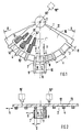
- two pole shoes 7 and 8 are arranged in a plane 6 parallel to the plane 5 of the ratchet wheel 1 at a mutual spacing of a tooth pitch z. These expediently have radially projecting tabs 9 and 10, which are connected by a permanent magnet 11 and are magnetically polarized by this in opposite polarity to one another. The permanent magnet 11 can thereby be attached outside the circumference of the ratchet wheel 1.
- the shape of the pole shoes 7, 8 is expediently chosen so that they are congruent with the teeth 4 of the ratchet wheel 1.
- a magnetic yoke in the form of a magnetizable strip is between the adjacent teeth 4 on the side of the pole wheel 1 facing away from the pole shoes 7, 8 on the side of the pole wheel 1 facing away from the pole shoes 7, 8 or a guide disk 12 made of soft magnetic material used in the exemplary embodiment is provided.
- This magnetic inference, i.e. the strip or the guide disk 12 extends over the area of the tooth gaps 3.
- the areas of the tooth gaps 3 are preferably covered to about 30 to 100%, in particular over 50%.
- the guide disk 12 and the ratchet wheel 1 are fixed to one another without axial play and in particular connected to one another, e.g. by riveting and / or spot welding.
- the width of the tooth gap 3 corresponds approximately to three to six times the tooth width B.
- the thickness D of the pole shoes 7, 8 corresponds approximately to the tooth width B.
- Locking wheels 1 are used which have a number of teeth of nZ or a tooth pitch of 1 n .z with n equal to an integer from eg 2 to 5.
- the free side 13 of the guide disk 12 and / or the one or both free side (s) 16 of the ratchet wheel 1 is light-reflecting, for example high-gloss, and is on these sides, as shown in FIG 1, a pattern similar to a spoked wheel with, for example, the number of spokes 14 corresponding to the number of teeth nZ corresponding to the tooth pitch 1 n .Z made of non-reflective or poorly reflective material, e.g. black matt lacquer.
- This printed side (s) 16 and / or 13 is or are scanned by a reflex light barrier.
- each pattern 14 'and 14 ⁇ is assigned a reflected light barrier 15' and 15 ⁇ .
- the reflex light barriers 15 ', 15 ⁇ are arranged on a radius vector or a diameter with different radius R1 and R2. The number of pulses and the left or right rotation can be determined by a corresponding electronic evaluation circuit and output as control signals.
Landscapes
- Physics & Mathematics (AREA)
- General Physics & Mathematics (AREA)
- Transmission And Conversion Of Sensor Element Output (AREA)
- Linear Motors (AREA)
Applications Claiming Priority (2)
| Application Number | Priority Date | Filing Date | Title |
|---|---|---|---|
| DE19893908751 DE3908751A1 (de) | 1989-03-17 | 1989-03-17 | Impulsgenerator |
| DE3908751 | 1989-03-17 |
Publications (2)
| Publication Number | Publication Date |
|---|---|
| EP0387710A2 true EP0387710A2 (fr) | 1990-09-19 |
| EP0387710A3 EP0387710A3 (fr) | 1993-02-03 |
Family
ID=6376555
Family Applications (1)
| Application Number | Title | Priority Date | Filing Date |
|---|---|---|---|
| EP19900104495 Withdrawn EP0387710A3 (fr) | 1989-03-17 | 1990-03-09 | Générateur d'impulsions |
Country Status (2)
| Country | Link |
|---|---|
| EP (1) | EP0387710A3 (fr) |
| DE (1) | DE3908751A1 (fr) |
Cited By (4)
| Publication number | Priority date | Publication date | Assignee | Title |
|---|---|---|---|---|
| GB2309518A (en) * | 1996-01-26 | 1997-07-30 | Asahi Optical Co Ltd | Encoder for detecting forward/reverse rotation |
| GB2313191A (en) * | 1993-06-08 | 1997-11-19 | Samsung Electronics Co Ltd | Robot cleaner direction sensor |
| GB2278937B (en) * | 1993-06-08 | 1998-01-14 | Samsung Electronics Co Ltd | Robot cleaner |
| US5821531A (en) * | 1996-01-26 | 1998-10-13 | Asahi Kogaku Kogyo Kabushiki Kaisha | Dual sensor encoder for detecting forward/reverse rotation having light modulating patterns with a predetermined phase different |
Family Cites Families (5)
| Publication number | Priority date | Publication date | Assignee | Title |
|---|---|---|---|---|
| US3482130A (en) * | 1967-12-28 | 1969-12-02 | Ford Motor Co | Reluctance pickup speed device for a speedometer cable |
| DE2054852C3 (de) * | 1969-11-10 | 1980-02-28 | Lucas Industries Ltd., Birmingham (Ver. Koenigreich) | Vorrichtung zur Messung der Drehzahl eines Fahrzeugrades |
| JPS5736569A (ja) * | 1980-08-13 | 1982-02-27 | Hitachi Ltd | Kaitenkinokaitensokudoseigyoyoshuhasuhatsudenki |
| JPS5917163A (ja) * | 1982-07-20 | 1984-01-28 | Nippon Soken Inc | 回転検出器 |
| JPS59144354A (ja) * | 1983-02-01 | 1984-08-18 | Seiko Epson Corp | 周波数発電機 |
-
1989
- 1989-03-17 DE DE19893908751 patent/DE3908751A1/de not_active Withdrawn
-
1990
- 1990-03-09 EP EP19900104495 patent/EP0387710A3/fr not_active Withdrawn
Cited By (6)
| Publication number | Priority date | Publication date | Assignee | Title |
|---|---|---|---|---|
| GB2313191A (en) * | 1993-06-08 | 1997-11-19 | Samsung Electronics Co Ltd | Robot cleaner direction sensor |
| GB2278937B (en) * | 1993-06-08 | 1998-01-14 | Samsung Electronics Co Ltd | Robot cleaner |
| GB2313191B (en) * | 1993-06-08 | 1998-01-14 | Samsung Electronics Co Ltd | Robot cleaner |
| GB2309518A (en) * | 1996-01-26 | 1997-07-30 | Asahi Optical Co Ltd | Encoder for detecting forward/reverse rotation |
| US5821531A (en) * | 1996-01-26 | 1998-10-13 | Asahi Kogaku Kogyo Kabushiki Kaisha | Dual sensor encoder for detecting forward/reverse rotation having light modulating patterns with a predetermined phase different |
| GB2309518B (en) * | 1996-01-26 | 1999-12-15 | Asahi Optical Co Ltd | Encoder for detecting forward/reverse rotation |
Also Published As
| Publication number | Publication date |
|---|---|
| DE3908751A1 (de) | 1990-09-20 |
| EP0387710A3 (fr) | 1993-02-03 |
Similar Documents
| Publication | Publication Date | Title |
|---|---|---|
| DE3821083C2 (fr) | ||
| DE4243778A1 (de) | Vorrichtung oder Verfahren zur Lageerkennung | |
| DE2840963A1 (de) | Optischer rotationskodierer | |
| DE19749140B4 (de) | Uhrwerk | |
| DE102004028855A1 (de) | Drehwinkeldetektor | |
| DE69025565T2 (de) | Vorrichtung und Verfahren für optische Kodierung | |
| DE2924590A1 (de) | Vorrichtung und verfahren zum erfassen der drehzahl und winkellage einer rotierenden welle | |
| EP0160811A2 (fr) | Dispositif de mesure photo-électrique | |
| DE2211049A1 (de) | Vorrichtung zum Auslesen eines platten förmigen Informationsträgers, der in opti scher Form kodierte Bild und/oder Tonsignale enthalt | |
| DE69001657T2 (de) | Optische kodierer. | |
| DE3640156C2 (fr) | ||
| DE19601242A1 (de) | Versatz-Erfassungseinrichtung | |
| DE3621564A1 (de) | Optischer codierer | |
| DE4306487A1 (en) | Detecting absolute displacement of object, e.g. servomotor shaft - operating micromachine with elements made from polycrystalline silicon in magnetic field as object moves, and storing relative positions of micromachine elements | |
| DE19601964A1 (de) | Aufbau eines Lenkwinkelsensormuduls | |
| WO1997026174A1 (fr) | Capteur d'angle de braquage avec systeme d'evaluation de la piste incrementielle pour la determination de la valeur absolue | |
| DE2817010C2 (de) | Einrichtung zur Abgabe von Impulsen bei der Vorbeibewegung von zwei relativ zueinander bewegbaren Teilen | |
| DE68906033T2 (de) | Sensoreinrichtung. | |
| EP0387710A2 (fr) | Générateur d'impulsions | |
| DE4311496C2 (de) | Handbetätigter Winkelgeber | |
| DE68918277T2 (de) | Rotierende kodiervorrichtung. | |
| EP0633545A1 (fr) | Compteur à rouleaux à plusieurs chiffres avec un codeur | |
| EP0566923B1 (fr) | Dispositif pour mesurer sans contact la position axiale d'un objet tournant | |
| DE19753775A1 (de) | Meßvorrichtung zur berührungslosen Erfassung eines Drehwinkels | |
| DE2243082B2 (de) | Symbolanzeigevorrichtung mit einer maskenplatte |
Legal Events
| Date | Code | Title | Description |
|---|---|---|---|
| PUAI | Public reference made under article 153(3) epc to a published international application that has entered the european phase |
Free format text: ORIGINAL CODE: 0009012 |
|
| AK | Designated contracting states |
Kind code of ref document: A2 Designated state(s): DE FR GB |
|
| RAP3 | Party data changed (applicant data changed or rights of an application transferred) |
Owner name: ALCATEL SEL AKTIENGESELLSCHAFT |
|
| PUAL | Search report despatched |
Free format text: ORIGINAL CODE: 0009013 |
|
| AK | Designated contracting states |
Kind code of ref document: A3 Designated state(s): DE FR GB |
|
| STAA | Information on the status of an ep patent application or granted ep patent |
Free format text: STATUS: THE APPLICATION IS DEEMED TO BE WITHDRAWN |
|
| 18D | Application deemed to be withdrawn |
Effective date: 19930804 |