EP0387989A2 - Schleifmaschine - Google Patents
Schleifmaschine Download PDFInfo
- Publication number
- EP0387989A2 EP0387989A2 EP90301120A EP90301120A EP0387989A2 EP 0387989 A2 EP0387989 A2 EP 0387989A2 EP 90301120 A EP90301120 A EP 90301120A EP 90301120 A EP90301120 A EP 90301120A EP 0387989 A2 EP0387989 A2 EP 0387989A2
- Authority
- EP
- European Patent Office
- Prior art keywords
- workpiece
- grinding
- tilting
- shaft
- rotor shaft
- Prior art date
- Legal status (The legal status is an assumption and is not a legal conclusion. Google has not performed a legal analysis and makes no representation as to the accuracy of the status listed.)
- Withdrawn
Links
- 230000000694 effects Effects 0.000 claims abstract description 11
- 230000001419 dependent effect Effects 0.000 claims 1
- 238000005259 measurement Methods 0.000 description 6
- 238000004519 manufacturing process Methods 0.000 description 4
- 238000001514 detection method Methods 0.000 description 3
- 230000002035 prolonged effect Effects 0.000 description 3
- 230000004044 response Effects 0.000 description 3
- 238000005452 bending Methods 0.000 description 1
- 238000010276 construction Methods 0.000 description 1
- 238000010586 diagram Methods 0.000 description 1
- 238000006073 displacement reaction Methods 0.000 description 1
- 238000003754 machining Methods 0.000 description 1
- 239000002699 waste material Substances 0.000 description 1
Images


Classifications
-
- B—PERFORMING OPERATIONS; TRANSPORTING
- B24—GRINDING; POLISHING
- B24B—MACHINES, DEVICES, OR PROCESSES FOR GRINDING OR POLISHING; DRESSING OR CONDITIONING OF ABRADING SURFACES; FEEDING OF GRINDING, POLISHING, OR LAPPING AGENTS
- B24B41/00—Component parts such as frames, beds, carriages, headstocks
- B24B41/04—Headstocks; Working-spindles; Features relating thereto
- B24B41/044—Grinding spindles with magnetic or electromagnetic bearings; Features related thereto
Definitions
- the present invention relates to a grinding machine.
- a grinding machine comprising first mounting means for mounting a workpiece which is to be ground; second mounting means for mounting a grinding member to effect grinding of the workpiece; drive means for effecting relative rotation of the first and second mounting means; and tilting means for effecting relative tilting of the first and second mounting means so that the workpiece can be accurately ground to predetermined dimensions characterised in that at least one of said first and second mounting means is constituted by a shaft which is mounted within a housing, the housing having electromagnets which are arranged to produce a magnetic force which is effective to float and radially support the shaft; the said tilting means electrically controlling the electromagnets so that the magnetic force produced by the latter can be adjusted to tilt the shaft with respect to the housing.
- the shaft is a rotor shaft which is driven by said drive means.
- the tilting means preferably includes measuring means for measuring the amount of taper present in a surface of the workpiece which is being ground, and calculating means connected to the measuring means for calculating the angle of relative tilt of the first and second mounting means required to correct for the said taper, the tilting means in operation producing the said relative tilt.
- the said electromagnets are preferably spaced from each other axially of the shaft, the tilting means in operation causing the magnetic forces produced by the respective electromagnets to be varied relative to each other.
- the rotor shaft is arranged to receive a grinding wheel thereon.
- the measuring means may be arranged to measure the amount of taper present in the bore of the workpiece.
- a grinding shaft S is elastically deformed due to grinding resistance during the grinding operation so that a grinding wheel G, which is carried by the grinding shaft S, is tilted. Therefore, a workpiece W is correspondingly set in an inclined position at a tilt angle ⁇ so as to avoid the tapering of a machined hole H.
- the workpiece W When carrying out internal grinding as shown in Figure 7, the workpiece W is normally ground while positioned parallel to the grinding shaft S, and the grinding shaft S is shifted in the cutting or radial direction A while maintaining this parallel relationship. In such positioning, the grinding shaft is bent by an angle of tilt ⁇ due to the grinding resistance. If the grinding operation were finished in these conditions, the hole of the workpiece W would have a taper angle ⁇ as shown in Figure 8.
- the workpiece W may be set in a position in which it is inclined at the angle ⁇ as shown in Figure 9.
- the grinding operation is carried out to avoid the tapering of the machined hole H which is shown in Figure 5.
- this tapering or broadening amount d exceeds a predetermined value over the product tolerance of the workpiece W
- the grinding wheel G is replaced by a new one to carry out the grinding of several further workpieces W until the taper again exceeds the tolerance.
- the current grinding wheel G is again replaced by another new one to maintain the cylindricality of the machined workpieces W within the tolerance during the sequential grinding of the workpieces.
- a chuck of the workpiece in order to place the workpiece W in an inclined position corresponding to the initial tilt ⁇ of the grinding shaft S, a chuck of the workpiece, a table for supporting the chuck, and a spindle or spindle table must also be inclined.
- These members have relatively great weight so that it is difficult to effect fine adjustment.
- the adjustment thereof needs specific intuition and skill, thereby causing problems such as long adjustment time and poor accuracy.
- the grinding wheel G has to be frequency replaced by a new one so as to maintain the initial sharpness. Therefore, the life of the grinding wheels is shortened and this causes increased production costs.
- the magnetic force produced by the electromagnets is electrically controlled to effect easy tilting of the rotor shaft so as thereby to tilt the grinding wheel.
- the response is excellent and fine adjustment can be easily effected.
- the adjustment moreover, does not need intuition or skill and can be carried out quickly. Further, the cylindricality of a machined workpiece can be ensured with a high degree of accuracy.
- a grinding machine comprises a magnetically supported spindle or housing 1 having a substantially cylindrical base 2 which constitutes an outer frame.
- a rotor shaft 3 is disposed in the base 2 so as to extend axially of the latter.
- a pair of radial magnetic bearings in the form of radial electromagnets 5 and 6 are provided in the base 2 adjacent opposite end portions of the rotor shaft 3 so as to magnetically float and radially support the rotor shaft 3.
- a motor 8 is disposed in the base 2 around an axially central portion of the rotor shaft 3 so as to drive the rotor shaft 3.
- a pair of axial magnetic bearings in the form of electromagnets 11 and 12 are disposed in the base 2 to control axial displacement of the rotor shaft 3, the electromagnets 11, 12 being disposed on opposite sides of a flange 10 which projects radially from a substantially central portion of the rotor shaft 3.
- a radial position sensor 14 is provided in the base 2 adjacent to the front radial electromagnet 5 so as to detect the radial position of the front of the rotor shaft 3, and another radial position sensor 15 is provided in the base 2 adjacent to the rear radial electromagnet 6 so as to detect the radial position of the rear of the rotor shaft 3. Further, an axial position sensor 16 is disposed adjacent to a step portion 3a formed at the front end portion of the rotor shaft 3 (the left side in Figure 1) so as to detect the axial position of the rotor shaft 3.
- a pair of mechanical bearings 18 and 19 are disposed in the base 2 around the opposite end portions of the rotor shaft 3 so as respectively to support the same at a reduced diameter portion 3b formed at the front end portion of the rotor shaft 3 and at another reduced diameter portion 3c formed at the rear end portion thereof.
- the rotor shaft 3 is thus directly and rotatably supported by the reduced diameter portions 3b and 3c when the radial electromagnets 5 and 6 are deenergized so that the rotor shaft 3 is no longer magnetically floated.
- a cylindrical grinding wheel 21 is attached to the front end of the reduced diameter portion 3b to grind a workpiece (not shown in Figure 1) when the rotor shaft 3 is rotated.
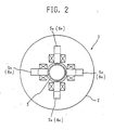
- the front radial electromagnet 5 is comprised of four sections 5a-5d disposed around the rotor shaft 3 equi-angularly
- the rear radial electromagnet 6 is also comprised of four sections 6a-6d disposed equi-angularly around the rotor shaft 3 and axially spaced from the front radial electromagnet 5.
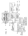
- a radial position detector circuit 20 operates according to signals from a pair of sensor components 14a and 14b of the front radial position sensor 14 to detect the front radial position of the rotor shaft 3, and a radial control circuit 22 operates according to the detection results to electrically control the radial electromagnet sections 5a and 5c to regulate the magnetic force produced thereby so as to maintain the rotor shaft 3 in a predetermined radial position.
- the rear radial electromagnet sections 6a and 6c are servo controlled through a pair of sensor components 15a and 15b of the rear radial position sensor 15, another radial position detector circuit 26 and another radial control circuit 23.
- the Figure 3 construction further includes an inner diameter measurement device 24 for measuring an inner diameter of a machined bore or hole H of a workpiece W which is held in a mounting means 30; a calculation circuit 25 for calculating the amount of taper of the machined hole H based on the measurement result; a CPU 27 for controlling tilting of the rotor shaft 3 according to the amount of taper; a memory 29; and a manual input unit 28.
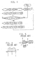
- step P1 the internal grinding of an individual workpiece W is carried out by means of the rotating grinding wheel 21.
- step P2 after finishing the grinding, the internal diameters of the opposite end portions of the machined bore H of the ground workpiece W are measured by means of the inner diameter measurement device 24.
- step P3 the amount of taper of the machined bore H is calculated by means of the calculation circuit 25 according to the result of the measurement effected by the measurement device 24.
- step P4 the calculated data is inputted into the CPU 27 (which constitutes the grinding machine controller) for effecting total control of the grinding machine.
- the amounts of taper of the ground workpieces W are sequentially determined, and the CPU 27 judges sequentially whether the thus obtained amounts of taper are within the tolerances. If the amounts of taper are within the tolerances, the grinding operation is continued as it is for following workpieces W.
- step P5 if an amount of taper exceeds the respective tolerance, the CPU 27 operates to compare the actual amount of taper with correlation data which have been provisionally stored in the memory 29 so as to calculate the amount of tilt ⁇ of the rotor shaft 3 which is effective to correct or avoid an excessive taper. Then in the step P6, the grinding wheel 21 is accordingly tilted by the calculated amount ⁇ through the supporting rotor shaft 3 so as thereby to continue the grinding operation for the subsequent workpiece.
- the CPU 27 operates according to the calculated amount of tilt to shift the detection signal fed from the front radial position detector circuit 20 to the front radial control circuit 22 in one direction, and to shift the other detection signal fed from the rear radial position detector sensor 26 to the rear radial control circuit 23 in the opposite direction. Consequently, the radial positions of the front and rear end portions of the rotor shaft 3 are moved from the central position in opposite directions, respectively, by means of the front and rear radial electromagnets 5 and 6 so as thereby to tilt the rotor shaft 3.
- the rotor shaft 3 can be rotated while having a tilt according to the calculated amount of tilt ⁇ . Accordingly, the grinding wheel 21 is also tilted by the same angular amount while rotating to carry out the grinding.
- the inner diameter measurement device 24; the calculation circuit 25 for calculating the amount of taper; the CPU 27; and the memory 29 constitute a tilting means operative to effect electrical control of the magnetically supporting forces of the radial electromagnets 5 and 6 for tilting the rotor shaft 3 with respect to the axis of the spindle 1.
- the response can be improved and fine adjustment can be facilitated.
- the adjustment of the tilting can be quickly carried out without specific intuition and skill.
- the grinding wheel 21 does not need to be frequency replaced by a new one.
- the grinding wheel 21 can be used for a long time to effect successive grinding of workpieces for a lengthy period. Thus the life of an individual grinding wheel can be prolonged so as to promote its efficient use and thereby reduce production costs.
- the tilting of the rotor shaft is effected automatically by means of the CPU 27 during the course of the sequential grinding of workpieces after the sharpness of the grinding wheel has varied.
- such tilting of the rotor shaft can be effected by manually inputting an instruction into the manual input unit 28 to control the CPU 27 at the time of the start of grinding for setting the rotor shaft.
- the grinding wheel is attached to the magnetically floated rotor shaft, and this rotor shaft is tilted with respect to the cylindrical axis of the workpiece to be machined.
- the tilting can be carried out relatively between the grinding wheel and the workpiece.
- the workpiece may be attached to a rotor shaft of a magnetically floating type spindle and this rotor shaft can be tilted.
- the rotating workpiece can be tilted with respect to a stationary grinding tool to achieve the same effect.
- the tilting means operates to electrically control the magnetic force produced by the radial electromagnets of the magnetically floating type spindle so as easily to tilt the rotor shaft.
- the grinding wheel is also easily tilted while effecting grinding of the workpieces. Accordingly, the response is improved and the adjustment is facilitated.
- the adjustment does not need intuition or skill and consequently there can be quick adjustment which thereby improves the cylindricality of the machined bore.
- the grinding wheel can be easily tilted to avoid or correct the excessive taper. Therefore, without frequent replacement or dressing of the grinding wheel, the grinding wheel can be used for a long time to effect the sequential grinding of a number of workpieces. Thus, the life of the grinding wheel can be prolonged for economical use thereof so as to reduce machining costs.
Landscapes
- Engineering & Computer Science (AREA)
- Mechanical Engineering (AREA)
- Grinding Of Cylindrical And Plane Surfaces (AREA)
- Constituent Portions Of Griding Lathes, Driving, Sensing And Control (AREA)
- Finish Polishing, Edge Sharpening, And Grinding By Specific Grinding Devices (AREA)
Applications Claiming Priority (2)
| Application Number | Priority Date | Filing Date | Title |
|---|---|---|---|
| JP60307/89 | 1989-03-13 | ||
| JP6030789A JPH01316168A (ja) | 1988-03-17 | 1989-03-13 | 研削盤 |
Publications (2)
| Publication Number | Publication Date |
|---|---|
| EP0387989A2 true EP0387989A2 (de) | 1990-09-19 |
| EP0387989A3 EP0387989A3 (de) | 1991-01-30 |
Family
ID=13138372
Family Applications (1)
| Application Number | Title | Priority Date | Filing Date |
|---|---|---|---|
| EP19900301120 Withdrawn EP0387989A3 (de) | 1989-03-13 | 1990-02-02 | Schleifmaschine |
Country Status (1)
| Country | Link |
|---|---|
| EP (1) | EP0387989A3 (de) |
Family Cites Families (3)
| Publication number | Priority date | Publication date | Assignee | Title |
|---|---|---|---|---|
| US4180946A (en) * | 1975-10-02 | 1980-01-01 | Maurice Brunet | Tool holding spindle assembly particularly for a grinding machine |
| CH623261A5 (en) * | 1978-07-14 | 1981-05-29 | Tschudin Werkzeugmasch | Process for the cylindrical grinding of cylindrical parts, and cylindrical grinding machine for carrying out this process |
| FR2606694B1 (fr) * | 1986-11-13 | 1989-03-24 | Europ Propulsion | Procede et dispositif d'usinage ultra-precis applique a l'execution de surfaces atypiques de revolution et aux usinages asservis |
-
1990
- 1990-02-02 EP EP19900301120 patent/EP0387989A3/de not_active Withdrawn
Also Published As
| Publication number | Publication date |
|---|---|
| EP0387989A3 (de) | 1991-01-30 |
Similar Documents
| Publication | Publication Date | Title |
|---|---|---|
| JP2516382B2 (ja) | 磁気軸受を主軸にもつ加工装置 | |
| US4956945A (en) | Internal grinder | |
| US5573443A (en) | Spindle and method for driving the same | |
| EP0324959B1 (de) | Verfahren und Vorrichtung zum Korrigieren von Reifenverformungen beim Profilschneiden | |
| US5024025A (en) | Control system of grinding machine | |
| EP1736278B1 (de) | Schleifverfahren | |
| JP2002001656A (ja) | トラバース円筒研削盤および長尺丸棒状のワークの円筒研削方法 | |
| US4998383A (en) | Means for resetting a cylindrical grinding machine | |
| EP0387989A2 (de) | Schleifmaschine | |
| JP2819129B2 (ja) | 接触位置検出装置および該装置を用いた工作機械 | |
| JPS6047061B2 (ja) | 鉄道車輛の車輪を再整形する方法 | |
| JPH07112671B2 (ja) | 磁気軸受をスピンドルにもつ加工装置 | |
| JPH11188621A (ja) | 研削盤におけるテーパ補正方法及びその装置 | |
| JPH01252358A (ja) | 撓み検知手段付スピンドル装置を備えた研削加工装置の制御方法 | |
| JP2000042867A (ja) | 回転型位置決め装置 | |
| JPH01240268A (ja) | 研削盤のドレス方法 | |
| JP2917085B2 (ja) | 研削盤の制御装置 | |
| JPH0645328Y2 (ja) | 研削盤の制御装置 | |
| JP2558201B2 (ja) | ボールナットねじ溝研削装置 | |
| JP2512753B2 (ja) | 研削盤の送り制御装置 | |
| JPH05192856A (ja) | 球面研削装置 | |
| JPH0899254A (ja) | スピンドル装置 | |
| JPH1110536A (ja) | ツルーイング装置及び方法 | |
| JPH106182A (ja) | 加工方法及び加工装置 | |
| JPH01252337A (ja) | 工作機械のピックフィード装置 |
Legal Events
| Date | Code | Title | Description |
|---|---|---|---|
| PUAI | Public reference made under article 153(3) epc to a published international application that has entered the european phase |
Free format text: ORIGINAL CODE: 0009012 |
|
| AK | Designated contracting states |
Kind code of ref document: A2 Designated state(s): DE FR |
|
| PUAL | Search report despatched |
Free format text: ORIGINAL CODE: 0009013 |
|
| AK | Designated contracting states |
Kind code of ref document: A3 Designated state(s): DE FR |
|
| STAA | Information on the status of an ep patent application or granted ep patent |
Free format text: STATUS: THE APPLICATION IS DEEMED TO BE WITHDRAWN |
|
| 18D | Application deemed to be withdrawn |
Effective date: 19910731 |