EP0388246A2 - Bewegbares Spielzeug mit Schwingungselement - Google Patents
Bewegbares Spielzeug mit Schwingungselement Download PDFInfo
- Publication number
- EP0388246A2 EP0388246A2 EP90400401A EP90400401A EP0388246A2 EP 0388246 A2 EP0388246 A2 EP 0388246A2 EP 90400401 A EP90400401 A EP 90400401A EP 90400401 A EP90400401 A EP 90400401A EP 0388246 A2 EP0388246 A2 EP 0388246A2
- Authority
- EP
- European Patent Office
- Prior art keywords
- toy
- accordance
- movable toy
- motor
- movable
- Prior art date
- Legal status (The legal status is an assumption and is not a legal conclusion. Google has not performed a legal analysis and makes no representation as to the accuracy of the status listed.)
- Withdrawn
Links
- 239000005060 rubber Substances 0.000 claims description 7
- 239000004744 fabric Substances 0.000 claims description 4
- 239000007779 soft material Substances 0.000 claims description 4
- 229920003002 synthetic resin Polymers 0.000 claims description 4
- 239000000057 synthetic resin Substances 0.000 claims description 4
- 230000000875 corresponding effect Effects 0.000 claims 2
- 238000010276 construction Methods 0.000 description 2
- 238000004519 manufacturing process Methods 0.000 description 2
- 239000000463 material Substances 0.000 description 2
- 229910000831 Steel Inorganic materials 0.000 description 1
- 230000002860 competitive effect Effects 0.000 description 1
- 239000004020 conductor Substances 0.000 description 1
- 238000010586 diagram Methods 0.000 description 1
- 230000005484 gravity Effects 0.000 description 1
- 238000012986 modification Methods 0.000 description 1
- 230000004048 modification Effects 0.000 description 1
- 239000010959 steel Substances 0.000 description 1
Images


Classifications
-
- A—HUMAN NECESSITIES
- A63—SPORTS; GAMES; AMUSEMENTS
- A63H—TOYS, e.g. TOPS, DOLLS, HOOPS OR BUILDING BLOCKS
- A63H11/00—Self-movable toy figures
- A63H11/02—Self-movable toy figures moved by vibrations produced by rotating eccentric weights
Definitions
- This invention relates to a movable toy, and more particularly to a movable soft toy that includes vibrating means and can be vibrated or moved in a predetermined direction.
- a movable toy to an immovable toy because a movable toy such as toy animal can be moved forward or backward while vibrating as if alive.
- the toy has to be provided with a mechanical device.
- Conventional mechanical devices which are housed within the toy body, generally consist of a plurality of gears interconnected with a drive mechanism through a pulley and a belt. Such toy can be vibrated at a stationary position, or moved forward or backward in a predetermined direction in response to the operation of the drive mechanism.
- the conventional mechanical device is generally composed of a plurality of various components and its operating mechanism is complicated. It is therefore burdensome to manufacture or assemble the components, which increases manufacturing cost to lower competitive power in the commercial market.
- a movable toy in accordance with the first embodiment of the present invention comprises a toy body and a vibrator.
- the vibrator has an upper cover and a lower cover and is mounted within the toy body.
- the vibrator includes a push member with a push plate on one end thereof.
- a push button switch mechanism is installed in a passthrough opening in the upper cover of the vibrator.
- a battery housing adapted to receive a battery is located within the covers of the vibrator as is a motor adapted to be energized into rotation by operation of the switch.
- a vibrating member is eccentrically mounted on the one side of the shaft of the motor.
- a movable soft toy in accordance with the first embodiment of the present invention, comprises a vibrator 1 having an upper cover 2 and a lower cover 3.
- the vibrator 1 is designed to be mounted on the bottom of the toy body 4 (see FIG. 4) which is shaped like an animal and made of some soft material such as cloth, rubber, or synthetic resin.
- a push member 5 having a circular push plate 5a on one end of a cylindrical body portion 5b is provided with a push button switch mechanism 6 at the other end thereof.
- Switch mechanism 6 may be of known design and includes an upper cam 7 and a lower cam 8 installed within a passthrough opening 2a in the bottom of the upper cover 2.
- the vibrator also includes a battery housing 9 adapted to receive a battery 10.
- the housing 9 is formed on both sides of the upper cover 2 and the lower cover 3 adjacent the push member 5.
- a motor 11 and a pair of switch plates 12 made of conductive material are fitted between the upper cover 2 and the lower cover 3.
- the switch plates 12 are each formed with an opening 12a and a pair of stepped portions 12b.
- a circular vibrating member 13 is eccentrically mounted on one end of the motor shaft 14.
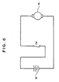
- the switching plates 12 and the push member 5 including the push button switch mechanism 6 form a switch means (SW) to connect and disconnect the motor 11 from the battery 10 (See FIG. 6), thus the vibrator 1 begins to vibrate or stops vibrating.
- SW switch means
- a coil spring 15 is resiliently installed around the cylindrical body portion 5b between the push plate 5a and the upper cover 2 as best seen in FIGS. 4 and 5.
- a pair of locking openings 16 are formed on both side surfaces of the upper cover 2 to receive corresponding locking lugs 17 of the lower cover 3, respectively.
- two pairs of mounting flanges 18, 18′ are formed on the inner surfaces of the upper cover 2 and lower cover 3 to receive two rubber rings 19 in which the motor 11 is supported.
- a guide protrusion 20, which is adapted to receive the opening 12a of the switch plates 12, is formed on both sides of the upper cover 2.
- a guide groove 21 which is adapted to receive the stepped portion 12b of the switch plates 12 is formed near each guide protrusion 20.
- the guide protrusion 20 and the guide groove 21 formed on the right side of the upper cover 2 are slightly higher than those formed on the left side of the upper cover 2 to leave a predetermined gap therebetween.
- a pair of guide slots (not shown) to receive corresponding guide protrusions 20 of the upper cover 2 are formed within each recess 22 of the lower cover 3. Accordingly, when the upper cover 2 and the lower cover 3 are assembled, they do not leave any clearance therebetween.
- Each end of the switch plates 12 is held between its respective guide protrusion 20 of the lower cover 3 and guide slot of the upper cover 2 to maintain the predetermined gap between the other overlapping ends to the switch plates 12.
- the push button switch mechanism 6 is provided with an upper cam 7 and a lower cam 8.
- the lower cam 8 is provided with a larger diameter portion having a pair of toothed portions 8a whose surfaces are cut away obliquely, a recess 8b which is formed longitudinally on the periphery thereof, and a smaller diameter portion which is adapted to be fitted within the cylindrical bore 5c of the push member 5.
- the recess 8b is adapted to cooperate with a stopper 23 formed in the passthrough opening 2a of the upper cover 2 so as to prevent rotation but permit slidable up and down movement.
- the upper cam 7 is provided with first and second toothed portions 7a, 7b whose surfaces are also cut away obliquely and a rectangular opening 7c formed between the toothed portions. Therefore, a pair of the toothed portions 8a, 8b of the lower cam 8 may contact preferentially the first or the second toothed portion 7a, 7b of the upper cam 7.
- the lower cam 8 whose recess 8b cooperates with the stopper 23 again moves straight up.
- the rectangular opening 7c of the upper cam 7 now coincides with the stopper 23 so that the stopper 23 is slidably received within the opening 7c. Accordingly the upper cam 7 moves down to disconnect the switch plates 12. Therefore DC current from the battery 10 to the motor 11 is cut off, the motor 11 stops rotating and the toy stops vibrating.
- the toy in accordance with the first embodiment of the present invention either vibrates or stops vibrating by selectively pressing the push member 5.
- the vibrating toy if it is laid on a flat surface such as a floor, it can be moved forward or backward. That is, the vibration induced by the vibrator 1 may change the friction force between the bottom face of the toy body 4 and the flat surface of the floor so that the friction force may vary from a maximum to a minimum value at the bottom face of the toy body 4 where the center of the graving exists. Therefore, the toy itself may be moved forward or backward in the direction upon which the combined forces exert.
- the center of the gravity of the vibrator 1 may be located at front portion of the toy body 4 so that the toy can be moved forward as shown in FIG. 4.
- the vibrator 1 is installed within the toy body 4 with the motor 11 being headed for backward movement, the toy may be moved backward as shown in FIG. 5. Therefore, the moving direction of the toy can be selected by changing the location and the mounting direction of the vibrator 1.
- the toy in accordance with the first embodiment of the present invention may not move in a straight line because the vibrating member 13 is mounted on only one end of the motor shaft 14. Thus the resultant force is headed in an oblique direction.
- FIG. 3 a second embodiment of the present invention in FIG. 3.
- the construction of the second embodiment is similar to that of the first embodiment except for the switch means (SW) and the vibrating member 13. Accordingly, the same reference numerals are given to the same components, respectively and detailed description of those now will be omitted.
- a vibrating member 13 is mounted on each end of the motor shafts 14, respectively and a spring-loaded push button switch 24 with a protrusion 24a is substituted for switch means (SW) of the first embodiment.
- the vibrating and moving pattern of the toy may be more stable due to the simple construction of the switch means (SW). That is, the push member 5 is provided with coil spring 15 as in FIG. 1. If the push plate 5a is pressed, the protrusion 24a of the push button switch 24, which is fitted within the rectangular bore 5c, moves up and the push button switch 24 is closed. Then DC current is supplied from the battery 10 to the motor 11 to rotate motor shafts 14. Therefore, the vibrating members 13 mounted on both ends of the motor shafts 14 rotate to produce a uniform vibration induced by the unbalanced rotational moment.
- SW switch means
- the toy moves in a straight line, forward or backward, owing to the resultant force which is the combined force of the weight of the vibrator 1 and the friction force between the toy body 4 and the floor.
- the toy can be moved forward or backward by preferentially installing the vibrator with its motor 11 headed for forward or backward motion.
- the push button switch 24 opens to stop the vibrating or moving operation of the toy. As described above, if the push plate 5a is pressed again, the toy is vibrated in a forward or backward motion.
- a movable toy incorporating the principles of the present invention can be vibrated and moved forward or backward in response to the vibration of the vibrating member 13 mounted eccentrically on one or both ends of the motor shafts 14.
- the toy may induce curiosity in children.
- the vibrator 1 which is mounted within the toy body 4 can be made of some soft material such as cloth, rubber, or synthetic resin as well as being simple to construct, the toy in accordance with the principles of the present invention can be applicable to any toy, regardless of its shape or material.
- each vibrating member is illustrated as being fixed to corresponding positions of the motor shafts, but each vibrating member can be fixed asymmetrically to the motor shafts. This can produce additional types of vibration and movement.
Landscapes
- Toys (AREA)
Applications Claiming Priority (4)
| Application Number | Priority Date | Filing Date | Title |
|---|---|---|---|
| KR891599U | 1989-02-16 | ||
| KR2019890001599U KR910007060Y1 (ko) | 1989-02-16 | 1989-02-16 | 봉제활동완구 |
| KR2019890016604U KR910009547Y1 (ko) | 1989-11-09 | 1989-11-09 | 활동 완구 |
| KR8916604U | 1989-11-09 |
Publications (2)
| Publication Number | Publication Date |
|---|---|
| EP0388246A2 true EP0388246A2 (de) | 1990-09-19 |
| EP0388246A3 EP0388246A3 (en) | 1990-12-05 |
Family
ID=26627985
Family Applications (1)
| Application Number | Title | Priority Date | Filing Date |
|---|---|---|---|
| EP19900400401 Withdrawn EP0388246A3 (en) | 1989-02-16 | 1990-02-14 | Movable toy with vibrating element |
Country Status (1)
| Country | Link |
|---|---|
| EP (1) | EP0388246A3 (de) |
Cited By (5)
| Publication number | Priority date | Publication date | Assignee | Title |
|---|---|---|---|---|
| GB2272649A (en) * | 1992-11-24 | 1994-05-25 | Sicke Steven Gresham | Motor driven playthings and games. |
| SG85158A1 (en) * | 1999-01-11 | 2001-12-19 | Tomy Co Ltd | Reaction toy |
| WO2003105981A1 (en) * | 2000-01-18 | 2003-12-24 | Kikkerland Design, Inc. | Self-propelled amusement device |
| US6826449B1 (en) * | 1997-12-30 | 2004-11-30 | Ali F. Abu-Taha | Method for producing natural motions |
| WO2014141572A1 (ja) * | 2013-03-15 | 2014-09-18 | 株式会社セガトイズ | 走行玩具 |
Family Cites Families (4)
| Publication number | Priority date | Publication date | Assignee | Title |
|---|---|---|---|---|
| GB1180384A (en) * | 1966-05-25 | 1970-02-04 | Bernard Stanley Benson | Improvements in and relating to Toys Activated by Oscillating or Rotating Weights |
| FR1564711A (de) * | 1968-02-21 | 1969-04-25 | ||
| US3530617A (en) * | 1968-07-02 | 1970-09-29 | Kurt Schwarz | Vibration driven vehicle |
| GB1595007A (en) * | 1978-05-30 | 1981-08-05 | Mitsubishi Pencil Co | Travelling toy |
-
1990
- 1990-02-14 EP EP19900400401 patent/EP0388246A3/en not_active Withdrawn
Cited By (7)
| Publication number | Priority date | Publication date | Assignee | Title |
|---|---|---|---|---|
| GB2272649A (en) * | 1992-11-24 | 1994-05-25 | Sicke Steven Gresham | Motor driven playthings and games. |
| GB2272649B (en) * | 1992-11-24 | 1995-12-06 | Sicke Steven Gresham | Motor driven playthings and games |
| US6826449B1 (en) * | 1997-12-30 | 2004-11-30 | Ali F. Abu-Taha | Method for producing natural motions |
| SG85158A1 (en) * | 1999-01-11 | 2001-12-19 | Tomy Co Ltd | Reaction toy |
| WO2003105981A1 (en) * | 2000-01-18 | 2003-12-24 | Kikkerland Design, Inc. | Self-propelled amusement device |
| WO2014141572A1 (ja) * | 2013-03-15 | 2014-09-18 | 株式会社セガトイズ | 走行玩具 |
| JP2014176557A (ja) * | 2013-03-15 | 2014-09-25 | Sega Toys:Kk | 走行玩具 |
Also Published As
| Publication number | Publication date |
|---|---|
| EP0388246A3 (en) | 1990-12-05 |
Similar Documents
| Publication | Publication Date | Title |
|---|---|---|
| US5221226A (en) | Movable toy | |
| JPH0637557Y2 (ja) | スイツチ装置 | |
| US5678312A (en) | Electric shaver with reduced vibration | |
| GB1565151A (en) | Electric shaver | |
| KR0157678B1 (ko) | 시소스위치 | |
| EP0388246A2 (de) | Bewegbares Spielzeug mit Schwingungselement | |
| US6506984B2 (en) | Rotary switch having click mechanism | |
| US3652963A (en) | Push button switch | |
| USRE35375E (en) | Movable toy | |
| US4893038A (en) | Device for limiting direction of rotation of synchronous motor | |
| JPH05215507A (ja) | センサ | |
| US5068633A (en) | Automatic canceling device for a winker | |
| US4121068A (en) | Polarity reversing electrical switch | |
| JPH08264075A (ja) | 多機能スイッチ | |
| US4426559A (en) | Push button switch having two resilient contacts operated at different times | |
| US3700843A (en) | Snap-in rigid lever actuating arrangement | |
| KR200171810Y1 (ko) | 키이 제조장치 | |
| KR100298507B1 (ko) | 스위치 | |
| JPS6010287Y2 (ja) | ジヤツク | |
| JPH026583Y2 (de) | ||
| JPS6355741B2 (de) | ||
| KR970009207B1 (ko) | 죠그셔틀 스위치 | |
| JP3658600B2 (ja) | ワイパモータ | |
| KR900003095Y1 (ko) | 브라쉬 (Brush) 고정판 고정 장치 | |
| JPS5854763Y2 (ja) | リレ− |
Legal Events
| Date | Code | Title | Description |
|---|---|---|---|
| PUAI | Public reference made under article 153(3) epc to a published international application that has entered the european phase |
Free format text: ORIGINAL CODE: 0009012 |
|
| AK | Designated contracting states |
Kind code of ref document: A2 Designated state(s): AT BE CH DE DK ES FR GB GR IT LI LU NL SE |
|
| PUAL | Search report despatched |
Free format text: ORIGINAL CODE: 0009013 |
|
| AK | Designated contracting states |
Kind code of ref document: A3 Designated state(s): AT BE CH DE DK ES FR GB GR IT LI LU NL SE |
|
| STAA | Information on the status of an ep patent application or granted ep patent |
Free format text: STATUS: THE APPLICATION IS DEEMED TO BE WITHDRAWN |
|
| 18D | Application deemed to be withdrawn |
Effective date: 19910507 |