EP0388345A2 - Optische Messkette für Winkel oder Lage mit Lichtleiterübertragung, mit Eigenlinearität- und -Referenzund bei Anwendung von einer oder mehreren Lichtquellen - Google Patents
Optische Messkette für Winkel oder Lage mit Lichtleiterübertragung, mit Eigenlinearität- und -Referenzund bei Anwendung von einer oder mehreren Lichtquellen Download PDFInfo
- Publication number
- EP0388345A2 EP0388345A2 EP90480038A EP90480038A EP0388345A2 EP 0388345 A2 EP0388345 A2 EP 0388345A2 EP 90480038 A EP90480038 A EP 90480038A EP 90480038 A EP90480038 A EP 90480038A EP 0388345 A2 EP0388345 A2 EP 0388345A2
- Authority
- EP
- European Patent Office
- Prior art keywords
- measurement
- optical
- light
- axis
- light waves
- Prior art date
- Legal status (The legal status is an assumption and is not a legal conclusion. Google has not performed a legal analysis and makes no representation as to the accuracy of the status listed.)
- Ceased
Links
Images



Classifications
-
- G—PHYSICS
- G01—MEASURING; TESTING
- G01D—MEASURING NOT SPECIALLY ADAPTED FOR A SPECIFIC VARIABLE; ARRANGEMENTS FOR MEASURING TWO OR MORE VARIABLES NOT COVERED IN A SINGLE OTHER SUBCLASS; TARIFF METERING APPARATUS; MEASURING OR TESTING NOT OTHERWISE PROVIDED FOR
- G01D5/00—Mechanical means for transferring the output of a sensing member; Means for converting the output of a sensing member to another variable where the form or nature of the sensing member does not constrain the means for converting; Transducers not specially adapted for a specific variable
- G01D5/26—Mechanical means for transferring the output of a sensing member; Means for converting the output of a sensing member to another variable where the form or nature of the sensing member does not constrain the means for converting; Transducers not specially adapted for a specific variable characterised by optical transfer means, i.e. using infrared, visible, or ultraviolet light
- G01D5/268—Mechanical means for transferring the output of a sensing member; Means for converting the output of a sensing member to another variable where the form or nature of the sensing member does not constrain the means for converting; Transducers not specially adapted for a specific variable characterised by optical transfer means, i.e. using infrared, visible, or ultraviolet light using optical fibres
-
- G—PHYSICS
- G01—MEASURING; TESTING
- G01D—MEASURING NOT SPECIALLY ADAPTED FOR A SPECIFIC VARIABLE; ARRANGEMENTS FOR MEASURING TWO OR MORE VARIABLES NOT COVERED IN A SINGLE OTHER SUBCLASS; TARIFF METERING APPARATUS; MEASURING OR TESTING NOT OTHERWISE PROVIDED FOR
- G01D5/00—Mechanical means for transferring the output of a sensing member; Means for converting the output of a sensing member to another variable where the form or nature of the sensing member does not constrain the means for converting; Transducers not specially adapted for a specific variable
- G01D5/26—Mechanical means for transferring the output of a sensing member; Means for converting the output of a sensing member to another variable where the form or nature of the sensing member does not constrain the means for converting; Transducers not specially adapted for a specific variable characterised by optical transfer means, i.e. using infrared, visible, or ultraviolet light
- G01D5/32—Mechanical means for transferring the output of a sensing member; Means for converting the output of a sensing member to another variable where the form or nature of the sensing member does not constrain the means for converting; Transducers not specially adapted for a specific variable characterised by optical transfer means, i.e. using infrared, visible, or ultraviolet light with attenuation or whole or partial obturation of beams of light
- G01D5/34—Mechanical means for transferring the output of a sensing member; Means for converting the output of a sensing member to another variable where the form or nature of the sensing member does not constrain the means for converting; Transducers not specially adapted for a specific variable characterised by optical transfer means, i.e. using infrared, visible, or ultraviolet light with attenuation or whole or partial obturation of beams of light the beams of light being detected by photocells
Definitions
- the present invention has for its object a referenced chain for angle measurement or position measurement, comprising only optical elements (transport of light by optical fiber to an optical measurement head and transport of information in return by optical fiber) and having an absolute character, that is to say not operating according to an incremental process.
- the detected signal is not proportional to the magnitude measured (angle or position).
- optical sensors with digital coding and transmission by fiber which include a high number of optical fibers associated with the various positions of the sensor; their resolution is naturally limited by the number of fibers put in place.
- Another known optical angle measurement device uses the absorption of a light beam on passing through an absorbent filter having the shape of a crown whose density depends linearly on the angular position; this device also has an optical referencing system for the measurement chain based on the optical Wheastone bridge method (a method that belongs to the public domain (see, for example, "a balancing technique in fiber sensors) modulated intensity optics ", B. CULSHAW et al., 2nd international conference on optical fibers, 1984, p.117, VDE-VERLAG GmbH Berlin).
- the main defect of this device is that the light beam does not coincide with the axis of rotation of the filter. This results in significant bulk.
- optical fiber couplers connecting four optical fibers, which prove to be unstable in difficult environmental conditions (vibrations, temperature variations, etc.). These instabilities are related to variations in the modal distribution of light energy in optical fibers.
- level of losses in this sensor led their inventors to use laser diodes in place of broad spectrum optical sources with the consequence of producing laser granularity at the level of the absorbent filter which greatly reduces its resolution and the repeatability of the measurements. .
- the encoder comprises: an element with a band whose transparency is complete with respect to two wavelengths L1 and L2 but varies according to the distance, angular or linear, for a third wavelength between L1 and L2; light emitting means emitting three beams of light at the three wavelengths; a first optical coupler mixing the beams; means for bidirectional optical fiber optic transmission (s); a second optical coupler dividing the light leaving the means into three beams after returning to the optical element and passing through the strip; three sensitive readers; and an electronic unit connected and determining the ratio between the average of the responses.
- position encoder whose code-carrying element comprises at least one band whose transparency varies, for a wavelength, in sine and / or cosine of the distance, angular or linear, from an origin, and which includes an opto-electronic transmitter, an opto-electronic reader, a processing unit, a bi-directional optical coupler, a bidirectional optical beam splitter-mixer, two micro-mirrors swiveling between a active position for returning the light to the strip and an inactive position, an autonomous energy supply source and an electronic signal processing unit which calculates the response of the reader when a micro-mirror is in the active position and when the two micro-mirrors are in the active position, the reader response when the two micro-mirrors are in the inactive position being deduced from the other responses.
- the reflective element (9) has several zones, having different light reflection coefficients, within two bands of different wavelength.
- An interposed element (51) is interposed between the end (7) and the reflective element (9), the interposed element having properties of light transmission which vary in space through the interposed element, in a transverse direction of the optical axis of the element (9).
- the interposed element (51) and the reflective element (9) are arranged in such a way that they can move, relatively to each other, in a direction transverse to the optical axis of the element ( 9).
- optical detector comprising an apparatus for directing the angular movement of a distant body lying around three perpendicular axes from a single point of observation.
- a compact and fully passive target is made to be attached to the body, the angular movement of which must be detected.
- the target reflects the light rays which represent the measurement functions, highest, lowest, and rotation.
- the reflected rays are optically detected and reduced to their components, along the highest, lowest and axes of rotation, which are represented visually through a single viewfinder.
- This device does not use optical fibers.
- JP-A-58 156802 this device does not allow angular measurement. It uses the principle of concealment and not filtering. There is no rotation measurement.
- the angle measuring device is absolute, that is to say non-incremental, intrinsically linear and referenced. It uses only optical components both at the level of the measurement head which constitutes the optical sensor itself, as well as the transport of the light waves towards the measurement head and of the light signals resulting from the measurement.
- the intrinsic linearity of the measurement is ensured by the very principle of the measurement and the properties of symmetry of the light beams at the level of the measurement head.
- the operation of the device according to the invention is independent of the modal distribution of the energy of the light waves inside the optical fibers; the device therefore has very high stability with respect to external disturbances exerted on the measuring chain (vibrations, temperature variations, etc.).
- this device containing only optical elements is naturally protected against electromagnetic disturbances.
- non-coherent light sources gives it excellent resolution, avoiding the appearance of laser granularity at the level of the measurement head.
- the measuring head has a very small footprint, which gives it a considerable advantage over the aforementioned systems.
- the device whatever the embodiment of the invention, comprises in particular a measuring head receiving one or more light waves coming from incoherent optical sources (broad spectrum centered around a wavelength) and transported by a fiber supply optics having a symmetry of revolution.
- the incident light beams are collimated and then intercepted by a set of diaphragms and / or filters (absorbent or interference), fixed and mobile, which constitutes the measurement system proper.
- the resulting light signals are then refocused and coupled to a return optical fiber which transports the signals to an intensity detector.
- Said device has a characteristic axis which is the axis of symmetry of the input and output optics; the diaphragms and / or filters are fixed or rotate around this axis.
- a single light wave is directed towards the measuring head and the measuring system consists of two diaphragms, one of which is fixed and the other capable of rotating around the axis of the head. optical.
- a means of referencing the measurement chain is provided by the implementation of an optical Wheastone bridge.
- the measurement system consists of a selective filter completely intercepting one of the two light waves and allowing the other to pass and a diaphragm or well from a second filter.
- the measurement system consists of a block of two selective semi-circular filters juxtaposed followed by a diaphragm or a second filter ; each element constituting the filter block allows one of the two light waves to pass completely and intercepts the other.
- the measurement system consists of a tiling, fixed or rotating, of three selective filters blocking one or more of the incident light waves and monitoring or preceded by a filter or fixed or rotating diaphragm.
- the measuring head has a main optical channel and a secondary optical channel eccentric with respect to the main channel making it possible to carry out a measurement intended to discern the angular sector of 180 ° of extent in which the angle measurement is carried out secondly, two return optical fibers making it possible to ensure the transfer of the different signals resulting from these measurements.
- the various optical elements making it possible to carry out the measurement can have geometrical and / or structural characteristics suitable for minimizing the effects of diffraction of the light waves at their borders.
- a means for controlling the intensities emitted by the light sources, at a constant level, is used.
- a mechanical reduction gear linked to the axis of rotation of the movable diaphragm of the measuring head, provides access to a greater range of angular measurement.
- a mechanical device is adapted to the measuring head enabling a rectilinear movement to be transformed into a rotary movement.
- the light beams, on which the measurement system operates have a perfect symmetry of revolution which results from the cylindrical symmetry of the fiber, the quality of the end of the fiber and the coincidence of the axis of the beam emerging from the supply and the axis of the measuring head.
- coherent optical sources can be used in place of broad spectrum sources.
- the return optical fiber next to the fiber supply optic so that the ends of the supply optical fiber and the return optical fiber are located in the focal plane of the fixed optical system and of symmetry of revolution intended to shape the light beam, and symmetrically with respect to to the axis of symmetry of the optics; concurrently, fixed or mobile optical elements, intended to reflect all or part of the incident light waves, are located inside the measurement head and are capable, if necessary, of participating directly in the measurement process.
- the device comprises a measurement head receiving a single non-coherent light wave coming from an optical source of broad spectrum centered around a given wavelength and transported by a fiber supply optics.
- the incident light beam is collimated, then intercepted by a set of two diaphragms, mobile and fixed, which constitutes the measurement system proper.
- the resulting light signal is then refocused and coupled to an output optical fiber which transports the signal to an intensity detector.
- the actual measurement system consists of two half-plane diaphragms whose edges pass through the axis of the system.
- the first diaphragm is fixed and intercepts half of the light beam collimated incident. It is followed by a movable diaphragm, capable of rotating around this axis and which intercepts a light energy proportional to the angle from which it is rotated.
- the measurement range of this device is therefore 180 °, with a resolution and precision which only depend on the quality of the mechanical device which guides the rotation of the mobile diaphragm.
- the symmetry of revolution of the light beam and the very principle of the measurement make it possible to overcome the problems linked to the modal distribution inside the fibers and to ensure an intrinsically linear measurement of the angle whose axis is rotated. driving the movable diaphragm.
- the assembly is compact and capable of a high degree of integration.
- the measurement chain of the device is referenced by an optical Wheastone bridge.
- the rotation mechanism of the movable diaphragm is multiplied and allows access to a greater range of measurement.
- the rotation mechanism of the movable diaphragm is coupled to a rack linked to a rectilinear displacement and allows access to an intrinsically linear measurement of a position.
- two non-coherent light waves of different wavelengths ⁇ 1 and ⁇ 2 are injected into an optical fiber which guides them to the measurement head.
- the actual measurement system differs from the system described according to the first embodiment of the present invention, in that one of the two diaphragms is replaced by a rotating blade which exclusively filters only one of the two light waves.
- the mobile element allowing the measurement to be made will be the blade or the diaphragm and may precede or follow the fixed element.
- the filter plate will either be a filter completely absorbing one of the two light waves, or an interference filter totally reflecting one of the two light waves.
- the axial symmetry of the two light beams is ensured in particular by the cylindrical symmetry of the supply fiber and the geometry of the measuring head.
- This property of axial symmetry of the two light beams and the very principle of the measurement mean that the two light waves can have different modal distributions at the level of the measurement head, without the measurement itself being affected. As a result, the intrinsic linearity of the measurement is ensured.
- the rotation mechanism of the movable diaphragm is multiplied and allows access to a greater range of measurement.
- the mechanism of rotation of the movable diaphragm is coupled to a rack linked to a rectilinear displacement and allows access to an intrinsically linear measurement of a position.
- two non-coherent light waves of different wavelengths ⁇ 1 and ⁇ 2 are injected into an optical fiber which guides them to the measurement head.
- the actual measurement system consists of a diaphragm and two juxtaposed semi-circular selective filters completely intercepting one of the two light waves and letting the other pass.
- the rotation mechanism of the movable diaphragm is multiplied and allows access to a greater range of measurement.
- the mechanism of rotation of the movable diaphragm is coupled to a rack linked to a rectilinear movement and allows access to an intrinsically linear measurement of a position.
- three non-coherent light waves of different wavelengths ⁇ 1, ⁇ 2 and ⁇ 3 are injected into an optical fiber which guides them to the measurement head.
- the actual measurement system consists of a tiling, fixed or rotating, absorbent or interference filters blocking one or more light waves among the previous ones, followed by a filter or a fixed or rotating diaphragm.
- the rotation mechanism of the mobile filter is multiplied and allows access to a greater measuring range.
- the rotation mechanism of the movable diaphragm is coupled to a rack linked to a rectilinear movement and allows access to an intrinsically linear measurement of a position.
- two non-coherent light waves of different wavelengths ⁇ 1 and ⁇ 2 are injected into an optical fiber which guides them to the measurement head.
- a collimating lens is followed by a diaphragm having, first, a circular opening centered on the axis of the measuring head and, second, a smaller eccentric circular opening.
- Two optical fibers are provided in return and consequently two focusing optics; a first operates in the axis of the measuring head and collects only the light selected by the main opening of the inlet diaphragm and the diaphragms and filter elements of the measuring head; the other optic collects the light coming from the eccentric opening of the diaphragm.
- the actual measurement system is made up of two semi-circular filters, just one placed, opaque to one or the other. two wavelengths, followed or preceded by a diaphragm whose edge passes precisely through the axis of the measuring head and which constitutes the rotating element of the system.
- the ratio of the difference of the intensities transmitted to their sum by the central channel of this measuring head provides access to a measuring range of 360 °, in a referenced manner.
- the transmission or not, by the rotating diaphragm, of light coming from the lateral opening of the diaphragm of the input optics makes it possible to identify the angular range (0 ° -180 ° or 180 ° -360 °) in which the measurement is carried out, which remains intrinsically linear.
- the rotation mechanism of the mobile filter is multiplied and allows access to a greater range of measurement.
- the mechanism of rotation of the movable diaphragm is coupled to a rack linked to a rectilinear movement and allows access to an intrinsically linear measurement of a position.
- the optical measurement head operates in reflection.
- the ends of the supply and return optical fibers are located in the focal plane of the collimating optical system and symmetrically with respect to the axis of symmetry AA ′ of the measuring head.
- the incident light beam is collimated, then intercepted by a set of movable and fixed diaphragms and / or filters which constitutes the actual measurement system.
- the resulting light beam is then reflected by a fixed or mobile plane mirror placed normally at the axis of symmetry AA ′, then focused by the optical system in the return optical fiber.
- the measurement head receives only a single non-coherent light wave
- the measurement system itself consists of two half-plane diaphragms whose edges pass through the axis of symmetry AA ′.
- the first diaphragm is fixed and intercepts half of the incident collimated light beam, it is followed by a mobile diaphragm, capable of rotating around the axis AA ′ and which intercepts a light energy proportional to the angle from which it is rotated.
- the optical measurement chain is referenced by an optical Wheastone bridge.
- two non-coherent light waves of different wavelength ⁇ 1 and ⁇ 2 are injected into the supply optical fiber.
- the measuring head has a plane interference filter located before the two diaphragms which constitutes the actual measuring system.
- This plane interference filter is normally placed at the axis of symmetry AA ′, it reflects the light wave ⁇ 1, and transmits the light wave ⁇ 2.
- the light wave ⁇ 1 reflected by the filter is focused by the optical system in the return optical fiber, and the amount of light reflected by the filter is independent of the position of the measurement system.
- the light wave ⁇ 2 is modulated by the measurement system composed of the two fixed and mobile diaphragms, the optical beam resulting from the light wave ⁇ 2 is then reflected by the plane mirror, then crosses the interference filter before being focused by the optical system in the return optical fiber.
- the measurement chain is referenced by making the ratio of the intensities of the two light waves transmitted by the return fiber.
- the control unit 1 contains two light sources 2 and 3 modulated in intensity at different frequencies f1 and f2.
- Connectors 4 and 5 allow the light coming from 2 and 3 to be coupled to the supply optical fibers 6 and 7.
- Each connector can be followed, if necessary, by a mode mixer and a non-propagative mode spillway (not shown in Figure 1).
- the fiber couplers 8 and 9 direct the light waves from the two sources 2 and 3 to the measuring head 10 and the couplers 11 and 12 which lead to the fibers 13 and 14.
- the fibers 13 and 14 are connected to the housing 1 by connectors 15 and 16.
- Light waves from fibers 13 and 14 are detected by photodiodes 17 and 18.
- An electronic module 19 ensures the modulation of the two light sources 2 and 3 and the processing of the signals collected by the photodiodes 17 and 18.
- the measuring head 10, represented by FIG. 2, plate 1/6, consists of a system 20 making it possible to collimate the light coming from the fiber 6 via the coupler 9 and to direct the parallel beam and cylindrical symmetry thus obtained, towards a fixed half-plane diaphragm 21 whose edge cuts the light beam at its axis AA ′.
- the resulting beam meets another diaphragm 22, of the same type, capable of rotating around the axis AA ′.
- This rotating diaphragm intercepts a fraction of the light energy transmitted by the previous one, proportional to the angle from which it is rotated.
- an optical system 23 makes it possible to focus the beam transmitted by all of the two diaphragms and to couple it to the return fiber 14 via the coupler 12.
- This transmission is independent of source or receiver drifts and is independent of line losses on the entire optical circuit (variations due to connectors or to the length of the lines, for example).
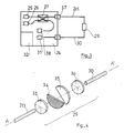
- FIG. 3, plate 2/6 represents an optical angle measurement chain according to the second version of the present invention.
- the control box 24 contains two light sources 25 and 26 of different wavelengths.
- a fiber coupler in X 27 makes it possible to direct the two waves emitted by the two sources 25 and 26 towards the connector 38 or else towards the photodiode 28.
- the connector 38 makes it possible to couple the light coming from the two sources 25 and 26 to the fiber supply optics 29.
- the connector 38 can be followed, if necessary, by a mode mixer and a non-propagative mode spillway (not shown in FIG. 3).
- the optical fiber 29 transports the light waves to the measurement head 30.
- the measurement signals are then transmitted to the control unit 24 by the optical fiber 31.
- the measurement signals are detected by the photodiode 32.
- An electronic module 33 makes it possible to synchronize the alternating emission of the two light sources 25 and 26 and the detection of the corresponding signals on the photodiode 32.
- This electronic module 33 also makes it possible to control the transmission power of the diodes 25 and 26 at a constant level, by using the signals delivered by the photodiode 28.
- the measuring head 30, represented by FIG. 4, consists of a system 34 making it possible to collimate the light coming from the supply fiber 29 and to direct the parallel beam and of cylindrical symmetry thus obtained, towards a fixed half-plane diaphragm 35 whose edge cuts the light beam at its axis AA ′.
- the resulting beam meets a filter 36 capable of rotating around the axis AA ′.
- This filter processed, only intercepts one of the two light waves.
- an optical system 37 makes it possible to couple the resulting beam to the return fiber 31.
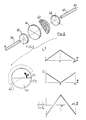
- FIG. 5 board 3/6 is an exploded view of the angular measuring head according to a preferred embodiment of the third embodiment of the present invention.
- This measuring head consists of a system 40 making it possible to collimate the light coming from the supply fiber 39 and to direct the parallel beam and of cylindrical symmetry thus obtained, towards a fixed block 41 consisting of two juxtaposed semi-circular filters intercepting each of the two light waves respectively and letting the other pass.
- the resulting beam meets a diaphragm 42 capable of rotating around the axis A-A ′.
- an optical system 43 makes it possible to couple the signals resulting luminous to the return fiber 44.
- Figure 6 plate 3/6, describes the operation of this measuring head. It comprises the plots of the intensities I1 and I2 detected at the two wavelengths in play ⁇ 1 and ⁇ 2, as a function of the angle ⁇ between the diaphragm and the block composed of the two filters F1, F2; each filter passing one of the two light waves and intercepting the other.
- the ratio (I1 - I2) / (I1 + I2) is directly proportional to the angle which the diaphragm is rotated on each of the angular ranges (0 ° -180 °) and (180 ° -360 °).
- FIG. 7, plate 4/6 is an exploded view of the angular measurement head according to a preferred embodiment of the fourth embodiment of the present invention.
- This measuring head is made up of a system 46 making it possible to collimate the light coming from the supply fiber 45 and to direct the parallel beam and of cylindrical symmetry thus obtained, towards a fixed block 47 consisting of three sectoral filters of 120 ° of angle in the center juxtaposed and letting pass, respectively each of the three light waves and intercepting the two others.
- the resulting beam meets a diaphragm 48 having the shape of an angular sector of angle at the center 120 °, capable of rotating around the axis AA ′.
- an optical system 49 makes it possible to couple the resulting signals to the return fiber 50.
- Figure 8 plate 4/6, describes the operation of this measuring head. It includes the plots of the ratios of the intensities detected at the three wavelengths in play ⁇ V , ⁇ R and ⁇ B.
- the ratios I V / I R , I B / I V and I R / I B provide access to a linear measurement of the angle which the diaphragm is rotated over the angular ranges (0 ° -120 °), (120 ° -240 °) and (240 ° -360 °) respectively.
- FIG. 9, plate 5/6 represents an optical angle measurement chain according to the fifth embodiment of the present invention.
- the control unit 51 contains two light sources 52 and 53 of different wavelengths.
- a fiber coupler in X 54 makes it possible to direct the two waves emitted by the two sources 52 and 53 towards the connector 55 or else towards the photodiode 56.
- the connector 55 makes it possible to couple the light coming from the two sources 52 and 53 to the fiber supply optics 57.
- the connector 55 can be followed, where appropriate, by a mode mixer and a non-propagative mode spillway (not shown in FIG. 9).
- the optical fiber 57 transports the light waves to the measurement head 58 which transmits the measurement signals to the control unit 51 by the optical fibers 59 and 60.
- the measurement signals are detected by the photodiodes 61 and 62.
- An electronic module 63 makes it possible to synchronize the alternating emission of the two light sources 52 and 53 and the detection of the signals on the photodiodes 61 and 62.
- This electronic module 63 also makes it possible to control the emission power of the diodes 52 and 53 at a constant level, by using the signals delivered by the photodiode 56.
- FIG 10, plate 5/6 is an exploded view of the measuring head 58 to better understand its operation.
- This measuring head consists of a system 64 making it possible to collimate the light coming from the supply fiber 57 and to direct the parallel beam and of cylindrical symmetry thus obtained, towards a diaphragm 65 having two circular openings: the first is centered on the axis AA ′ and the second is eccentric; they are respectively qualified as “main” and "secondary".
- the light having passed through the main opening encounters a fixed block 66 consisting of two juxtaposed semi-circular filters intercepting each of the two light waves respectively and letting the other pass.
- the resulting beam meets a diaphragm 67 capable of rotating around the axis A-A ′.
- an optical system 68 makes it possible to couple the resulting beam to the return fiber 59.
- the light having passed through the secondary opening of the diaphragm 65 may or may not be intercepted by the rotating diaphragm 67. When it is not intercepted by this diaphragm 67, it is refocused by the optics 69 and coupled to the second fiber of back 60.
- Photodiodes 61 and 62 respectively collect the waves coming from the "main” and “secondary” measurement channels and transported by the return optical fibers 59 and 60.
- the signal detected by photodiode 61 makes it possible to identify in which plane angular sector is performed the measurement: (0 ° -180 °) or (180 ° -360 °).
- FIG 11, plate 6/6 is an exploded view of the angular measuring head according to a preferred embodiment of the sixth embodiment of the present invention.
- This measurement head consists of an optical system 72 making it possible to collimate the light coming from the optical fiber supply 70 and to refocus the return light on the return optical fiber 71.
- the ends of the optical supply fibers 70 and back 71 are located in the focal plane of the optical system 72 and symmetrically with respect to the axis of symmetry AA ′.
- the collimated beam with symmetry of revolution from the optical system 72 meets a plane interference filter 73 normally located at the axis of symmetry AA ′.
- the wavelength ⁇ 1 is reflected by the filter 73, and is focused by the optical system 72 in the return optical fiber 71.
- the collimated optical beam with symmetry of revolution of the wavelength ⁇ 2 is transmitted by the interference filter 73, it meets a fixed half-plane diaphragm 74 whose edge cuts the light beam at the level of the axis AA ′.
- the resulting beam meets another diaphragm 75 of the same type, capable of rotating around the axis AA ′.
- This rotating diaphragm intercepts a fraction of the light energy transmitted by the previous one proportional to the angle from which it is rotated.
- the beam then meets a plane mirror 76 normally located at the axis AA ′.
- the optical beam reflected by the mirror crosses the interference filter 73 and is focused in the return optical fiber 71 by the optical system 72.
- Figure 12 is a variant of the sixth embodiment according to which the half-plane diaphragm 75 is integral with the plane mirror 76; the assembly of the diaphragm 75 and of the mirror 76 being capable of rotating around the axis A-A ′.
- the operation of this embodiment is identical to that shown in FIG. 11.
- the device whatever the embodiment of the invention, can be used in any application involving an angle or position measurement. It does not include any electrical or electronic element, apart from the control unit which can be kept far from the place of measurement; it is therefore particularly recommended in an explosive, irradiated environment or in the presence of strong electromagnetic disturbances.
- the "in-line" geometry of the measuring head that is to say the coincidence of the optical and mechanical axes, makes it possible to obtain a real miniaturization of the device, particularly interesting in the fields of aeronautics and robotics.
- the device whatever the embodiment of the invention, makes it possible to overcome any referencing problem possibly linked to conditions that are difficult to use (vibrations, temperature variations, etc.).
Landscapes
- Physics & Mathematics (AREA)
- General Physics & Mathematics (AREA)
- Optical Transform (AREA)
- Length Measuring Devices By Optical Means (AREA)
Applications Claiming Priority (2)
| Application Number | Priority Date | Filing Date | Title |
|---|---|---|---|
| FR8903370A FR2644239B1 (fr) | 1989-03-13 | 1989-03-13 | Chaine de mesure d'angle ou de position optique et a transmission par fibres optiques intrinsequement lineaire et reference utilisant une ou plusieurs sources lumineuses |
| FR8903370 | 1989-03-13 |
Publications (2)
| Publication Number | Publication Date |
|---|---|
| EP0388345A2 true EP0388345A2 (de) | 1990-09-19 |
| EP0388345A3 EP0388345A3 (de) | 1991-12-18 |
Family
ID=9379694
Family Applications (1)
| Application Number | Title | Priority Date | Filing Date |
|---|---|---|---|
| EP19900480038 Ceased EP0388345A3 (de) | 1989-03-13 | 1990-03-09 | Optische Messkette für Winkel oder Lage mit Lichtleiterübertragung, mit Eigenlinearität- und -Referenzund bei Anwendung von einer oder mehreren Lichtquellen |
Country Status (3)
| Country | Link |
|---|---|
| US (1) | US5087811A (de) |
| EP (1) | EP0388345A3 (de) |
| FR (1) | FR2644239B1 (de) |
Families Citing this family (4)
| Publication number | Priority date | Publication date | Assignee | Title |
|---|---|---|---|---|
| SE9100916L (sv) * | 1991-03-27 | 1992-09-28 | Nobeltech Electronics Ab | Laservarnare |
| JP2002043673A (ja) * | 2000-07-28 | 2002-02-08 | Furukawa Electric Co Ltd:The | 光モジュール組立方法及び組立装置 |
| FR2850750B1 (fr) * | 2003-02-05 | 2005-03-04 | Actaris Sas | Dispositif de detection optique pour compteur |
| CN100365389C (zh) * | 2005-10-14 | 2008-01-30 | 清华大学 | 开关式数字角位移传感器及其应用 |
Family Cites Families (12)
| Publication number | Priority date | Publication date | Assignee | Title |
|---|---|---|---|---|
| SE415397B (sv) * | 1978-06-02 | 1980-09-29 | Asea Ab | Fiberoptiskt metdon |
| US4356397A (en) * | 1980-06-18 | 1982-10-26 | Westinghouse Electric Corp. | Optical valve position sensor system |
| US4560272A (en) * | 1980-12-10 | 1985-12-24 | The Perkin-Elmer Corporation | Three-axis angle sensor |
| JPS58156802A (ja) * | 1982-03-15 | 1983-09-17 | Toshiba Corp | 光センサ装置 |
| EP0095273A1 (de) * | 1982-05-21 | 1983-11-30 | Gec Avionics Limited | Optische Methode zur Messung von Verschiebungen |
| GB8325921D0 (en) * | 1983-09-28 | 1983-11-02 | Marconi Avionics | Optical method of measuring displacement |
| JPS6085318A (ja) * | 1983-10-17 | 1985-05-14 | Showa Electric Wire & Cable Co Ltd | 光ロ−タリ−センサ |
| US4587513A (en) * | 1984-06-25 | 1986-05-06 | Energy Innovations, Inc. | Noncontact shaft angle detector |
| US4743119A (en) * | 1985-08-22 | 1988-05-10 | Mitsubishi Denki Kabushiki Kaisha | Optical measuring apparatus |
| AU6215186A (en) * | 1985-09-06 | 1987-03-12 | University Of Liverpool, The | Displacement measurement |
| GB8531149D0 (en) * | 1985-12-18 | 1986-01-29 | Smiths Industries Plc | Optical transducers |
| US4947036A (en) * | 1986-10-03 | 1990-08-07 | Conax Buffalo Corporation | Self-monitoring optical sensor having a ratiometric output signal |
-
1989
- 1989-03-13 FR FR8903370A patent/FR2644239B1/fr not_active Expired - Fee Related
-
1990
- 1990-03-09 EP EP19900480038 patent/EP0388345A3/de not_active Ceased
- 1990-03-13 US US07/492,564 patent/US5087811A/en not_active Expired - Fee Related
Also Published As
| Publication number | Publication date |
|---|---|
| US5087811A (en) | 1992-02-11 |
| FR2644239B1 (fr) | 1994-04-01 |
| EP0388345A3 (de) | 1991-12-18 |
| FR2644239A1 (fr) | 1990-09-14 |
Similar Documents
| Publication | Publication Date | Title |
|---|---|---|
| EP0347277B1 (de) | Interferometrischer Sensor und seine Anwendung in einer interferometrischen Vorrichtung | |
| JP3464081B2 (ja) | 波長分波器 | |
| US8184285B2 (en) | Method and apparatus using volume holographic wavelength blockers | |
| CN102970073A (zh) | 一种光性能监控装置和系统 | |
| EP0027763A1 (de) | Verfahren und Apparat zur Abstandsmessung durch Laserinterferometrie mit zwei Wellenlängen | |
| CN116804588A (zh) | 一种光栅衍射效率测量装置 | |
| EP0058592B1 (de) | Optische Anordnung zur Fouriertransformation und optischer Korrelator zu deren Anwendung | |
| WO1990000721A1 (fr) | Dispositif de lecture par coherence de capteur optique | |
| EP0018873B1 (de) | Kompakte optische Koppelungsvorrichtung und solch eine Vorrichtung enthaltender interferometrischer Gyrometer mit einer optischen Faser | |
| EP0388345A2 (de) | Optische Messkette für Winkel oder Lage mit Lichtleiterübertragung, mit Eigenlinearität- und -Referenzund bei Anwendung von einer oder mehreren Lichtquellen | |
| FR2589233A1 (fr) | Codeur optique analogique de reperage de position | |
| CN101023388A (zh) | 用于布拉格光栅可调谐滤光器的方法和装置 | |
| FR2848664A1 (fr) | Detecteur de position, forme et reflectivite d'une surface | |
| FR2728678A1 (fr) | Capteur du type modulation optique et appareil d'instrumentation de processus utilisant celui-ci | |
| FR2588653A1 (fr) | Capteur optique de position | |
| CN111060890B (zh) | 激光雷达设备 | |
| EP0448415A1 (de) | Abstandsdetektionsanordnung einer physikalischen Grösse durch Reflektion | |
| US11821791B1 (en) | Techniques for reducing optical ghosts in a gratings-based optical spectrum analyzer (OSA) | |
| EP4312006B1 (de) | Beugungsgittermonochromator | |
| EP0487391A1 (de) | Mehrwegiger bidirektionaler optischer Sende- und Empfangsmodul und diesen verwendende Relaisstation | |
| US20260071914A1 (en) | Elimination of optical ghosts in optical spectral analyzers through a scanning spectral filter | |
| EP0591911B1 (de) | Interferometer bestehend aus einer integrierten Anordnung und einem reflektierenden Teil, die durch eine Messzone voneinander getrennt sind | |
| JP2000292644A (ja) | 光モジュールおよび光波長モニタ方法 | |
| CA2680015A1 (fr) | Systeme de metrologie optique | |
| KR100292809B1 (ko) | 파장 분할 다중된 광신호의 파장과 광 세기와 광신호 대 잡음비를 측정하는 장치 |
Legal Events
| Date | Code | Title | Description |
|---|---|---|---|
| PUAI | Public reference made under article 153(3) epc to a published international application that has entered the european phase |
Free format text: ORIGINAL CODE: 0009012 |
|
| AK | Designated contracting states |
Kind code of ref document: A2 Designated state(s): AT BE CH DE DK ES FR GB GR IT LI LU NL SE |
|
| PUAL | Search report despatched |
Free format text: ORIGINAL CODE: 0009013 |
|
| AK | Designated contracting states |
Kind code of ref document: A3 Designated state(s): AT BE CH DE DK ES FR GB GR IT LI LU NL SE |
|
| 17P | Request for examination filed |
Effective date: 19920521 |
|
| 17Q | First examination report despatched |
Effective date: 19950621 |
|
| GRAG | Despatch of communication of intention to grant |
Free format text: ORIGINAL CODE: EPIDOS AGRA |
|
| STAA | Information on the status of an ep patent application or granted ep patent |
Free format text: STATUS: THE APPLICATION HAS BEEN REFUSED |
|
| 18R | Application refused |
Effective date: 19970203 |