EP0388623A2 - Dispositif pour montage et démontage des portes coulissantes des meubles - Google Patents
Dispositif pour montage et démontage des portes coulissantes des meubles Download PDFInfo
- Publication number
- EP0388623A2 EP0388623A2 EP90102569A EP90102569A EP0388623A2 EP 0388623 A2 EP0388623 A2 EP 0388623A2 EP 90102569 A EP90102569 A EP 90102569A EP 90102569 A EP90102569 A EP 90102569A EP 0388623 A2 EP0388623 A2 EP 0388623A2
- Authority
- EP
- European Patent Office
- Prior art keywords
- door
- caused
- swingable
- rail
- clamp member
- Prior art date
- Legal status (The legal status is an assumption and is not a legal conclusion. Google has not performed a legal analysis and makes no representation as to the accuracy of the status listed.)
- Withdrawn
Links
Images
Classifications
-
- E—FIXED CONSTRUCTIONS
- E05—LOCKS; KEYS; WINDOW OR DOOR FITTINGS; SAFES
- E05D—HINGES OR SUSPENSION DEVICES FOR DOORS, WINDOWS OR WINGS
- E05D15/00—Suspension arrangements for wings
- E05D15/06—Suspension arrangements for wings for wings sliding horizontally more or less in their own plane
- E05D15/08—Suspension arrangements for wings for wings sliding horizontally more or less in their own plane consisting of two or more independent parts movable each in its own guides
-
- E—FIXED CONSTRUCTIONS
- E05—LOCKS; KEYS; WINDOW OR DOOR FITTINGS; SAFES
- E05D—HINGES OR SUSPENSION DEVICES FOR DOORS, WINDOWS OR WINGS
- E05D15/00—Suspension arrangements for wings
- E05D15/06—Suspension arrangements for wings for wings sliding horizontally more or less in their own plane
- E05D15/0621—Details, e.g. suspension or supporting guides
- E05D15/0626—Details, e.g. suspension or supporting guides for wings suspended at the top
- E05D15/063—Details, e.g. suspension or supporting guides for wings suspended at the top on wheels with fixed axis
-
- E—FIXED CONSTRUCTIONS
- E06—DOORS, WINDOWS, SHUTTERS, OR ROLLER BLINDS IN GENERAL; LADDERS
- E06B—FIXED OR MOVABLE CLOSURES FOR OPENINGS IN BUILDINGS, VEHICLES, FENCES OR LIKE ENCLOSURES IN GENERAL, e.g. DOORS, WINDOWS, BLINDS, GATES
- E06B3/00—Window sashes, door leaves, or like elements for closing wall or like openings; Layout of fixed or moving closures, e.g. windows in wall or like openings; Features of rigidly-mounted outer frames relating to the mounting of wing frames
- E06B3/32—Arrangements of wings characterised by the manner of movement; Arrangements of movable wings in openings; Features of wings or frames relating solely to the manner of movement of the wing
- E06B3/34—Arrangements of wings characterised by the manner of movement; Arrangements of movable wings in openings; Features of wings or frames relating solely to the manner of movement of the wing with only one kind of movement
- E06B3/42—Sliding wings; Details of frames with respect to guiding
- E06B3/46—Horizontally-sliding wings
- E06B3/4663—Horizontally-sliding wings specially adapted for furniture
-
- E—FIXED CONSTRUCTIONS
- E05—LOCKS; KEYS; WINDOW OR DOOR FITTINGS; SAFES
- E05D—HINGES OR SUSPENSION DEVICES FOR DOORS, WINDOWS OR WINGS
- E05D15/00—Suspension arrangements for wings
- E05D15/06—Suspension arrangements for wings for wings sliding horizontally more or less in their own plane
- E05D15/0621—Details, e.g. suspension or supporting guides
- E05D15/0626—Details, e.g. suspension or supporting guides for wings suspended at the top
- E05D15/0656—Bottom guides
-
- E—FIXED CONSTRUCTIONS
- E05—LOCKS; KEYS; WINDOW OR DOOR FITTINGS; SAFES
- E05Y—INDEXING SCHEME ASSOCIATED WITH SUBCLASSES E05D AND E05F, RELATING TO CONSTRUCTION ELEMENTS, ELECTRIC CONTROL, POWER SUPPLY, POWER SIGNAL OR TRANSMISSION, USER INTERFACES, MOUNTING OR COUPLING, DETAILS, ACCESSORIES, AUXILIARY OPERATIONS NOT OTHERWISE PROVIDED FOR, APPLICATION THEREOF
- E05Y2600/00—Mounting or coupling arrangements for elements provided for in this subclass
- E05Y2600/10—Adjustable
- E05Y2600/30—Adjustment motion
- E05Y2600/32—Rotary motion
-
- E—FIXED CONSTRUCTIONS
- E05—LOCKS; KEYS; WINDOW OR DOOR FITTINGS; SAFES
- E05Y—INDEXING SCHEME ASSOCIATED WITH SUBCLASSES E05D AND E05F, RELATING TO CONSTRUCTION ELEMENTS, ELECTRIC CONTROL, POWER SUPPLY, POWER SIGNAL OR TRANSMISSION, USER INTERFACES, MOUNTING OR COUPLING, DETAILS, ACCESSORIES, AUXILIARY OPERATIONS NOT OTHERWISE PROVIDED FOR, APPLICATION THEREOF
- E05Y2600/00—Mounting or coupling arrangements for elements provided for in this subclass
- E05Y2600/10—Adjustable
- E05Y2600/30—Adjustment motion
- E05Y2600/32—Rotary motion
- E05Y2600/322—Rotary motion around a horizontal axis
-
- E—FIXED CONSTRUCTIONS
- E05—LOCKS; KEYS; WINDOW OR DOOR FITTINGS; SAFES
- E05Y—INDEXING SCHEME ASSOCIATED WITH SUBCLASSES E05D AND E05F, RELATING TO CONSTRUCTION ELEMENTS, ELECTRIC CONTROL, POWER SUPPLY, POWER SIGNAL OR TRANSMISSION, USER INTERFACES, MOUNTING OR COUPLING, DETAILS, ACCESSORIES, AUXILIARY OPERATIONS NOT OTHERWISE PROVIDED FOR, APPLICATION THEREOF
- E05Y2600/00—Mounting or coupling arrangements for elements provided for in this subclass
- E05Y2600/40—Mounting location; Visibility of the elements
- E05Y2600/46—Mounting location; Visibility of the elements in or on the wing
-
- E—FIXED CONSTRUCTIONS
- E05—LOCKS; KEYS; WINDOW OR DOOR FITTINGS; SAFES
- E05Y—INDEXING SCHEME ASSOCIATED WITH SUBCLASSES E05D AND E05F, RELATING TO CONSTRUCTION ELEMENTS, ELECTRIC CONTROL, POWER SUPPLY, POWER SIGNAL OR TRANSMISSION, USER INTERFACES, MOUNTING OR COUPLING, DETAILS, ACCESSORIES, AUXILIARY OPERATIONS NOT OTHERWISE PROVIDED FOR, APPLICATION THEREOF
- E05Y2900/00—Application of doors, windows, wings or fittings thereof
- E05Y2900/20—Application of doors, windows, wings or fittings thereof for furniture, e.g. cabinets
Definitions
- the invention relates to a device for easily assembling and disassembling slidable doors to and from pieces of furniture, which is meant for being applied to the lower side of horizontally slidable doors, in order to simplify the door assembly and disassembly to and from the respective door-guiding rails, whenever this work needs to be done from one side of the rails, and which may be used for other purposes.
- this object is attained by fitting the door-sliding wheel, or a door-sliding shoe, to be associated with the lower side of a slidable door, on a swingable body, which when a slidable door is being assembled to a piece of furniture, initially lies in a horizontal rest position substantially at right angles with the slidable door, and which while this door is being turned about the respective upper rail, so as to have its lower side drawn close to the respective, channel-shaped lower rail, is caused to cooperate either directly, or through inserted parts, with one side of this latter rail or with other stationary parts, whereby the said swingable body fitted with a door-sliding wheel or shoe, is caused to swing upwardly, is correctly inserted into the said channel-shaped lower rail, and is brought into an end-of-stroke upward position, in which the said swingable body is stably held, owing to its direct or indirect cooperation with retaining, snapping or friction means.
- the lower side of the door needs only to be pulled away from the respective, channel-shaped lower rail.
- the swingable body fitted with the door-sliding wheel or shoe is then caused to swing downwardly, and is caused to get out of the respective, channel-shaped lower rail, so that it is sufficient to lift the door for having the same released from the respective upper rail, and disassembled from the piece of furniture to which this door was assembled.
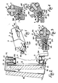
- references A1 and A2 denote two horizontally slidable doors respectively fitted, or in the course of being fitted on a piece of furniture M, which in the upper portion of their inward face are respectively provided with door sliding and guiding means of any suitable known type, such as pairs of grooved wheels R1, R2, carried by the door-supporting members S1, S2, and which are slidable on respective upper rails B1, B2 secured to the horizontal upper side of a piece of furniture M forepart having an opening Q.
- the door-sliding devices D are mounted on the lower side of the slidable doors A1, A2, and are caused to cooperate with respective, channel-shaped lower rails B3, B4 secured to the horizontal lower side of the said piece of furniture M forepart having an opening Q.
- the lower rails B3, B4 need to be located at different levels, so that according to the substantially known illustrative arrangement shown in Figure 2, the rail B4 for the door A2 should lie at a lower level than the rail B3 for the door A1.
- One or more door-supporting members S3, S4, supporting in turn the respective devices D may of course be provided on each slid able door A1, A2.
- the device D comprises a clamp member 1 made preferably of loaded nylon, or of any other suitable material, and having a "C" profile, such that the free end of the door-supporting member S3 can be clamped between the arms of the clamp member 1, and can be secured thereto by means of screws, rivets, or any like suitable means, threaded through a pair of bores 2 in the free ends 101 of the said clamp member arms.
- the clamp member 1 is integrally formed with a pair of respective, parallel, equal lugs 201 extending away from the door-supporting member S3, and giving the clamp member a substantially "U"-like configuration.
- the lugs 201 are provided with through bores 3 preferably of a same diameter, which are in-line with each other on a common axis, which is parallel to the planes in which lie the arms of the clamp member 1, and to the rails B3, B4, and a steel pivot 4 with a round cross-section, is pressure-fitted by its ends into these bores.
- a body 5 also made preferably of loaded nylon, or of any other suitable material, is fitted between the lugs 101, 201 by its one end provided with a bore having a slightly greater diameter than the bores 3, and which can be set in line therewith, whereby the pivot 4 is threaded through body 5 which, when required, may be caused to freely swing about the said pivot.
- the said swingable body 5 is substantially prismatic in shape, with a substantially drop-like profile in cross-section and, more particularly, it is fulcrumed about pivot 4 by the bored end portion of its tapered narrow side.
- the said body 5 gradually flares out in the direction away from pivot 4.
- the wide portion of the swingable body 5 is intermediately formed with a transversal slot 6, in which a door-sliding wheel 7, preferably of a suitable plastics material, is rotatably fitted, and is held in position by a pivot 8 pressure-fitted into a respective recess formed in the said body 5.
- the wheel 7 has a rounded peripheral surface, and projects from either sides of said slot 6 by an equal amount of its periphery.
- the end portion of body 5 which lies over the wheel 7, has an isosceles triangular profile, with its apex being suitably beveled for the purposes to be disclosed hereinafter.
- the swingable body 5 is also provided on its tapered narrow side with a further member 205 having a tooth-like profile in cross-section, which is suitably spaced apart from the tooth-like profiled member 105, and extends in parallel relation therewith, and which is caused to bear on a rib 301 provided on the rear end of the clamp member 1 lower arm, and comes to be clamped between the said tooth-like profiled members 105 and 205.
- the members 105, 205, and 301 are preferably so provided as to extend throughout their length along the side edge of the tapering right-hand side and the tapered narrow side of body 5, and across the clamp member 1, respectively, but it is understood that the said members may be differently sized.
- the swingable body 5 is thus stably held in its horizontal rest position.
- the upper arm of the clamp member 1 is provided at its rear end with a further, suitably profiled rib 401 which is parallel to the rib 301 on the rear end of the clamp member 1 lower arm, and between the said ribs 401, 301 a recessed portion 9 is provided, having, for example, an arcuate profile, or any other suitable profile.
- the swingable body 5 is provided on that portion of its tapered narrow side which is adjacent to pivot 4 about which this body is fulcrumed, with an arcuately profiled section 305 which does not interfere with any part of the clamp member 1, and at the end of its tapering left-hand side, as seen in Figures 3, 4 and 5, is formed with a rib 405 extending parallel to pivot 4, and having a suitably convex profile, for the purposes to be disclosed hereinafter.
- a member 505 having a wing-like profile in cross-section, with its right-hand side 10, as seen in Figures 3, 4, 5, being suitably beleveled, and which extends from the tapering left-hand side of body 5.
- the said beveled side 10 of the wing-like profiled member 505 is linked to body 5 by a connecting section 11, and lies in a properly spaced apart, substantially parallel relation with the said rib 405.
- the said wing-like profiled member 505 is directed upwardly. Thanks to the provision of the said con necting section 11, the swingable body 5 of the device D for the door A1 can be easily fitted into the respective door-guiding, channel-shaped rail B3, as disclosed hereinafter
- the rib 405 in body 5 is at first caused to frictionally pass over the rib 401 on the rear end of the clamp member 1 upper arm.
- the said rib 405 is then caused to cooperate with the recessed portion 9, and is pushed downward, into abutment therewith ( Figure 5), thanks to the particular profiles of the said ribs 405, 401 and the said recessed portion 9 being caused to cooperate with each other, when the side of the wing-like profiled member 505, which is opposite to its beveled side 10, comes to bear against the upper arm of the clamp member 1, whereby the body 5 is firmly held in its upright operative position, in which the pivot 8 for the wheel 7 is directed vertically.
- the swingable body 5 of the device D according to the invention is slidably connected to the channel-shaped rail B3, as follows.
- the body 5 of the device D is so sized, so located and oriented relative to the channel shaped lower rails B3, B4 (see Figure 3), that when the door A1 has been hung by its upper wheels R1 from the respective upper rail B1, and the lower side of door A1 is being drawn close to, and pushed against the lower rail B3, the beveled side 10 of the wing-like profiled member 505 is caused to bear on the outward face of the external side of the channel-shaped rail B3, which has its free end preferably formed with a rounded edge 12, in order to avoid any undesired friction and stresses, when the said rail B3 is caused to cooperate with the said body 5.
- the wheel 7 may not be provided, and the body 5 may be used as a sliding shoe.
- the use may be contemplated of rolling means different from the wheel 7 and being otherwise arranged.
- a roller may be, for example, used, which is fitted in a cantilevered manner on the swingable body 5, and is formed with one conical, or suitably rounded end, for its cooperation with the internal side of the rail B3, B4, the said roller being provided in place of the said body 5 end portion having a triangular profile.
- the body 5 may be, for example, stably held in its rest and in its operative position, respectively shown in Figure 3 and 5, by the provision of means other than the described means, such as a pin or an elastically loaded ball accomodated in body 5 (or in the clamp member 1, 201), which is caused to snappingly cooperate with recesses formed in the clamp member 1, 201, or in pivot 4, provided that this pivot be rotatively locked (or in body 5).
- the body 5 may be stably held at least in its angular operative position, by parts of its wing-like profiled member 505 being caused to snappingly cooperate with mating parts of the clamp member 1.
- the upward swinging movement of body 5 may be also initially promoted by suitably shaped parts of the said body being caused to cooperate with the internal side of the rail B3 or B4 that guides the respective device D, and the said side may be suitably shaped, so as to be caused to perform the function of a cam.
- the body 5 may be urged upwardly by an elastic means, and may be held in the position shown in Figure 3, by a bolt member being, for example, longitudinally slidably fitted on the door-supporting member S3, and extending across the clamp member 1, and which is caused to cooperate with recessed or projecting parts in that portion of body 5 which is adjacent to pivot 4, about which this body is fulcrumed.
- the bolt member may be incorporated in body 5, and may be connected to a trigger-like member, which by being moved into abutment with parts of a piece of furniture or of the lower rail B3 or B4, at the time a door A1 or A2 is being assembled, is so triggered as to release the swingable body 5, that will automatically get into this rail, without any particular pushing action on the to-be-assembled door A1 or A2 being required.
- the swingable body 5 may be held in its upright operative position shown in Figure 5, only by the action of spring means, and/or also by the action of frictionally or snappingly operating locking means.
- the swingable body 5 may be caused to swing around a virtual axis which can be obtained, for example, by the members 5, 1 being connected to each other by means of small cradles or suitable levers.
Landscapes
- Engineering & Computer Science (AREA)
- Mechanical Engineering (AREA)
- Civil Engineering (AREA)
- Structural Engineering (AREA)
- Support Devices For Sliding Doors (AREA)
Applications Claiming Priority (2)
| Application Number | Priority Date | Filing Date | Title |
|---|---|---|---|
| IT8912459A IT1233025B (it) | 1989-03-23 | 1989-03-23 | Dispositivo per facilitare la messa in opera e lo smontaggio di ante scorrevoli per mobili o per altri usi |
| IT1245989 | 1989-03-23 |
Publications (2)
| Publication Number | Publication Date |
|---|---|
| EP0388623A2 true EP0388623A2 (fr) | 1990-09-26 |
| EP0388623A3 EP0388623A3 (fr) | 1990-12-27 |
Family
ID=11140410
Family Applications (1)
| Application Number | Title | Priority Date | Filing Date |
|---|---|---|---|
| EP19900102569 Withdrawn EP0388623A3 (fr) | 1989-03-23 | 1990-02-09 | Dispositif pour montage et démontage des portes coulissantes des meubles |
Country Status (3)
| Country | Link |
|---|---|
| US (1) | US5076018A (fr) |
| EP (1) | EP0388623A3 (fr) |
| IT (1) | IT1233025B (fr) |
Cited By (6)
| Publication number | Priority date | Publication date | Assignee | Title |
|---|---|---|---|---|
| BE1015521A3 (nl) * | 2003-05-16 | 2005-05-03 | Louage & Wisselinck Nv | Kantelsysteem. |
| EP1813752A1 (fr) * | 2005-10-12 | 2007-08-01 | Caimi Export S.P.A. | Meuble aver des portes coulissantes parallelles et non coplanaires |
| WO2008125973A3 (fr) * | 2007-04-13 | 2009-01-15 | System Holz Spa | Patin de glissement pour portes de garde-robe |
| DE102014114339A1 (de) | 2014-10-02 | 2016-04-07 | Hettich-Heinze Gmbh & Co. Kg | Führungseinrichtung zur Führung einer Schiebetür und Schrankmöbel |
| DE202019102727U1 (de) | 2019-05-15 | 2019-07-12 | Rennerich Gmbh | Führungsvorrichtung für Schiebetüren |
| DE202017007616U1 (de) | 2016-05-25 | 2023-08-04 | Hettich-Heinze Gmbh & Co. Kg | Möbel mit einem an einem Laufprofil verfahrbaren Schiebeelement und einer Führungseinrichtung |
Families Citing this family (14)
| Publication number | Priority date | Publication date | Assignee | Title |
|---|---|---|---|---|
| US5632119A (en) * | 1993-03-05 | 1997-05-27 | Eduardo V. Bruno | Sliding door arrangement for a containment space |
| AR247854A1 (es) * | 1993-03-05 | 1995-04-28 | Ingenieria Moderna S A | Disposicion de puerta corrediza para vehiculos |
| US6416144B1 (en) * | 2000-03-31 | 2002-07-09 | Steris Inc. | Sterilizer horizontal motorized sliding door closure |
| ATE373762T1 (de) * | 2003-07-03 | 2007-10-15 | Home Decor Holding Company | Schiebetür |
| DE10336026A1 (de) * | 2003-08-01 | 2005-02-17 | Spirella Gmbh | Schiebetürführung |
| AU2005260228A1 (en) * | 2004-06-30 | 2006-01-12 | Fletcher Building Holdings Limited | Improvements in/or relating to sliding panels |
| US20070033874A1 (en) * | 2005-08-12 | 2007-02-15 | Home Decor Holding Company | Concealed top track system for sliding doors |
| DE202009014882U1 (de) * | 2009-12-18 | 2011-05-05 | Hettich-Heinze Gmbh & Co. Kg | Beschlaggarnitur für zwei Schiebetürflügel |
| DE102010037940A1 (de) * | 2010-10-04 | 2012-04-05 | Hettich-Heinze Gmbh & Co. Kg | Schiebetür-Rollenführung sowie Anordnung einer Schiebetür-Rollenführung an einem Möbel |
| ITPD20110127A1 (it) * | 2011-04-15 | 2012-10-16 | Topp S P A A Socio Unico | Struttura di attuatore lineare particolarmente per porte scorrevoli e per serramenti scorrevoli in generale |
| US8905500B2 (en) | 2011-05-13 | 2014-12-09 | Steelcase Inc. | Storage assembly includes a base assembly, a first cabinet assembly and a second cabinet assembly with each slidable with respect to the base assembly |
| ES2762167T3 (es) * | 2012-07-11 | 2020-05-22 | Hawa Sliding Solutions Ag | Dispositivo de guiado, carro y carril de rodadura |
| US10494858B2 (en) * | 2016-02-03 | 2019-12-03 | Rite-Hite Holding Corporation | Insulated doors with restorable breakaway sections |
| GB2591456B (en) * | 2020-01-22 | 2023-04-05 | Knorr Bremse Rail Systems Uk Ltd | Platform screen door |
Family Cites Families (15)
| Publication number | Priority date | Publication date | Assignee | Title |
|---|---|---|---|---|
| US1996310A (en) * | 1934-03-29 | 1935-04-02 | Art Metal Construction Co | Mounting for doors and the like |
| US2791006A (en) * | 1955-07-12 | 1957-05-07 | Joseph L Eichler | Sliding door assembly |
| US3138830A (en) * | 1962-07-30 | 1964-06-30 | Scharge Jack | Sliding doors |
| US3166801A (en) * | 1963-05-09 | 1965-01-26 | Morrison Internat Corp | Sliding door assembly |
| GB1082771A (en) * | 1965-01-15 | 1967-09-13 | Hill Aldam And Company Ltd E | Improvements in sliding doors or windows and rollers therefor |
| DE1559840C3 (de) * | 1966-06-07 | 1975-09-18 | Eltreva Ag, Aesch (Schweiz) | Rollenlager für Schiebefenster |
| FR1515116A (fr) * | 1967-01-16 | 1968-03-01 | Prefabriquee De Maxevillestuda | élément de fermeture coulissant |
| US3701179A (en) * | 1971-09-30 | 1972-10-31 | Arthur T Cox | Guides for sliding doors |
| US4176497A (en) * | 1978-04-17 | 1979-12-04 | Pullman Incorporated | Sliding door and threshold arrangement for a railway passenger car compartment |
| US4268996A (en) * | 1978-11-15 | 1981-05-26 | Ford Motor Company | Track for sliding closure |
| US4353186A (en) * | 1979-07-19 | 1982-10-12 | Offterdinger Hermoff F | Runner wheel assembly |
| US4486980A (en) * | 1983-01-20 | 1984-12-11 | Jannel & Son Body Company | Track and latch assembly for slidable door |
| GB2162225B (en) * | 1984-07-18 | 1987-09-09 | Genaplast Pty Ltd | Sliding door mechanism |
| US4873741A (en) * | 1987-03-31 | 1989-10-17 | Columbia Manufacturing Corporation | Sliding door roller apparatus |
| US4769949A (en) * | 1987-05-26 | 1988-09-13 | Usg Industries, Inc. | Tub and shower door enclosure having free-floating self-adjusting lower guide assembly |
-
1989
- 1989-03-23 IT IT8912459A patent/IT1233025B/it active
-
1990
- 1990-02-09 EP EP19900102569 patent/EP0388623A3/fr not_active Withdrawn
- 1990-06-22 US US07/542,046 patent/US5076018A/en not_active Expired - Fee Related
Cited By (6)
| Publication number | Priority date | Publication date | Assignee | Title |
|---|---|---|---|---|
| BE1015521A3 (nl) * | 2003-05-16 | 2005-05-03 | Louage & Wisselinck Nv | Kantelsysteem. |
| EP1813752A1 (fr) * | 2005-10-12 | 2007-08-01 | Caimi Export S.P.A. | Meuble aver des portes coulissantes parallelles et non coplanaires |
| WO2008125973A3 (fr) * | 2007-04-13 | 2009-01-15 | System Holz Spa | Patin de glissement pour portes de garde-robe |
| DE102014114339A1 (de) | 2014-10-02 | 2016-04-07 | Hettich-Heinze Gmbh & Co. Kg | Führungseinrichtung zur Führung einer Schiebetür und Schrankmöbel |
| DE202017007616U1 (de) | 2016-05-25 | 2023-08-04 | Hettich-Heinze Gmbh & Co. Kg | Möbel mit einem an einem Laufprofil verfahrbaren Schiebeelement und einer Führungseinrichtung |
| DE202019102727U1 (de) | 2019-05-15 | 2019-07-12 | Rennerich Gmbh | Führungsvorrichtung für Schiebetüren |
Also Published As
| Publication number | Publication date |
|---|---|
| IT8912459A0 (it) | 1989-03-23 |
| US5076018A (en) | 1991-12-31 |
| EP0388623A3 (fr) | 1990-12-27 |
| IT1233025B (it) | 1992-03-14 |
Similar Documents
| Publication | Publication Date | Title |
|---|---|---|
| US5076018A (en) | Device for easily assembling and disassembling slidable doors to and from pieces of furniture | |
| CA2351287C (fr) | Patin de frein pour fenetre a guillotine ou porte | |
| US4854077A (en) | Fail-safe tip-lock shoe | |
| US4908907A (en) | Furniture hinge including hinge arm releasably connected to mounting plate | |
| US5704080A (en) | Shower support bracket | |
| US4553873A (en) | Connecting fitting for releasably connecting two platelike furniture members | |
| US6048285A (en) | Bearing structure for vertical blinds and rollers shades | |
| US4927198A (en) | Locking device for windows/sliding doors | |
| CZ115897A3 (en) | Pulley mechanism | |
| NO874646L (no) | Stoettearm for aapnbare vinduer, doerer o.l. | |
| CA2252448A1 (fr) | Connecteurs | |
| US6840011B2 (en) | Window panel balance apparatus and method | |
| US5009034A (en) | Closure support | |
| US6019329A (en) | Clamps | |
| US2988392A (en) | Combination door holder and stopper | |
| HUE034971T2 (en) | Self-closing device for sliding doors | |
| US6874742B2 (en) | Clamp device | |
| EP2145067B1 (fr) | Patin de glissement pour portes de garde-robe | |
| CA2118075A1 (fr) | Mecanisme de reglage du siege pour fauteuil pivotant | |
| DE3630446C2 (de) | Möbelscharnier | |
| JPH04228785A (ja) | ヒンジ | |
| EP1703053A2 (fr) | Charnière pour un appareil ménager | |
| KR100415805B1 (ko) | 미닫이문 프리스톱 장치 | |
| DE10011712B4 (de) | Christbaumständer | |
| US3745607A (en) | Mounting system |
Legal Events
| Date | Code | Title | Description |
|---|---|---|---|
| PUAI | Public reference made under article 153(3) epc to a published international application that has entered the european phase |
Free format text: ORIGINAL CODE: 0009012 |
|
| AK | Designated contracting states |
Kind code of ref document: A2 Designated state(s): AT CH DE ES FR GB GR LI SE |
|
| PUAL | Search report despatched |
Free format text: ORIGINAL CODE: 0009013 |
|
| AK | Designated contracting states |
Kind code of ref document: A3 Designated state(s): AT CH DE ES FR GB GR LI SE |
|
| 17P | Request for examination filed |
Effective date: 19910222 |
|
| RAP1 | Party data changed (applicant data changed or rights of an application transferred) |
Owner name: CINETTO F.LLI S.R.L. |
|
| 17Q | First examination report despatched |
Effective date: 19910909 |
|
| STAA | Information on the status of an ep patent application or granted ep patent |
Free format text: STATUS: THE APPLICATION IS DEEMED TO BE WITHDRAWN |
|
| 18D | Application deemed to be withdrawn |
Effective date: 19920901 |