EP1703053A2 - Charnière pour un appareil ménager - Google Patents
Charnière pour un appareil ménager Download PDFInfo
- Publication number
- EP1703053A2 EP1703053A2 EP05025514A EP05025514A EP1703053A2 EP 1703053 A2 EP1703053 A2 EP 1703053A2 EP 05025514 A EP05025514 A EP 05025514A EP 05025514 A EP05025514 A EP 05025514A EP 1703053 A2 EP1703053 A2 EP 1703053A2
- Authority
- EP
- European Patent Office
- Prior art keywords
- hinge
- door hinge
- door
- hinge according
- spring
- Prior art date
- Legal status (The legal status is an assumption and is not a legal conclusion. Google has not performed a legal analysis and makes no representation as to the accuracy of the status listed.)
- Withdrawn
Links
- 238000006073 displacement reaction Methods 0.000 claims abstract description 32
- 230000006835 compression Effects 0.000 claims description 24
- 238000007906 compression Methods 0.000 claims description 24
- 230000004888 barrier function Effects 0.000 claims description 19
- 230000000295 complement effect Effects 0.000 claims description 3
- 230000003993 interaction Effects 0.000 claims description 3
- 238000005406 washing Methods 0.000 claims description 3
- 238000010411 cooking Methods 0.000 description 4
- 238000004140 cleaning Methods 0.000 description 2
- 238000000197 pyrolysis Methods 0.000 description 2
- 230000000903 blocking effect Effects 0.000 description 1
- 238000001816 cooling Methods 0.000 description 1
- 238000010438 heat treatment Methods 0.000 description 1
- 238000000034 method Methods 0.000 description 1
- 238000005096 rolling process Methods 0.000 description 1
- 238000010257 thawing Methods 0.000 description 1
Images


Classifications
-
- F—MECHANICAL ENGINEERING; LIGHTING; HEATING; WEAPONS; BLASTING
- F24—HEATING; RANGES; VENTILATING
- F24C—DOMESTIC STOVES OR RANGES ; DETAILS OF DOMESTIC STOVES OR RANGES, OF GENERAL APPLICATION
- F24C15/00—Details
- F24C15/02—Doors specially adapted for stoves or ranges
- F24C15/023—Mounting of doors, e.g. hinges, counterbalancing
-
- E—FIXED CONSTRUCTIONS
- E05—LOCKS; KEYS; WINDOW OR DOOR FITTINGS; SAFES
- E05D—HINGES OR SUSPENSION DEVICES FOR DOORS, WINDOWS OR WINGS
- E05D11/00—Additional features or accessories of hinges
- E05D11/10—Devices for preventing movement between relatively-movable hinge parts
- E05D11/1007—Devices for preventing movement between relatively-movable hinge parts with positive locking
-
- E—FIXED CONSTRUCTIONS
- E05—LOCKS; KEYS; WINDOW OR DOOR FITTINGS; SAFES
- E05F—DEVICES FOR MOVING WINGS INTO OPEN OR CLOSED POSITION; CHECKS FOR WINGS; WING FITTINGS NOT OTHERWISE PROVIDED FOR, CONCERNED WITH THE FUNCTIONING OF THE WING
- E05F1/00—Closers or openers for wings, not otherwise provided for in this subclass
- E05F1/08—Closers or openers for wings, not otherwise provided for in this subclass spring-actuated, e.g. for horizontally sliding wings
- E05F1/10—Closers or openers for wings, not otherwise provided for in this subclass spring-actuated, e.g. for horizontally sliding wings for swinging wings, e.g. counterbalance
- E05F1/12—Mechanisms in the shape of hinges or pivots, operated by springs
- E05F1/1246—Mechanisms in the shape of hinges or pivots, operated by springs with a coil spring perpendicular to the pivot axis
- E05F1/1253—Mechanisms in the shape of hinges or pivots, operated by springs with a coil spring perpendicular to the pivot axis with a compression spring
- E05F1/1261—Mechanisms in the shape of hinges or pivots, operated by springs with a coil spring perpendicular to the pivot axis with a compression spring for counterbalancing
-
- E—FIXED CONSTRUCTIONS
- E05—LOCKS; KEYS; WINDOW OR DOOR FITTINGS; SAFES
- E05F—DEVICES FOR MOVING WINGS INTO OPEN OR CLOSED POSITION; CHECKS FOR WINGS; WING FITTINGS NOT OTHERWISE PROVIDED FOR, CONCERNED WITH THE FUNCTIONING OF THE WING
- E05F1/00—Closers or openers for wings, not otherwise provided for in this subclass
- E05F1/08—Closers or openers for wings, not otherwise provided for in this subclass spring-actuated, e.g. for horizontally sliding wings
- E05F1/10—Closers or openers for wings, not otherwise provided for in this subclass spring-actuated, e.g. for horizontally sliding wings for swinging wings, e.g. counterbalance
- E05F1/12—Mechanisms in the shape of hinges or pivots, operated by springs
- E05F1/1246—Mechanisms in the shape of hinges or pivots, operated by springs with a coil spring perpendicular to the pivot axis
- E05F1/1269—Mechanisms in the shape of hinges or pivots, operated by springs with a coil spring perpendicular to the pivot axis with a traction spring
- E05F1/1276—Mechanisms in the shape of hinges or pivots, operated by springs with a coil spring perpendicular to the pivot axis with a traction spring for counterbalancing
-
- E—FIXED CONSTRUCTIONS
- E05—LOCKS; KEYS; WINDOW OR DOOR FITTINGS; SAFES
- E05Y—INDEXING SCHEME ASSOCIATED WITH SUBCLASSES E05D AND E05F, RELATING TO CONSTRUCTION ELEMENTS, ELECTRIC CONTROL, POWER SUPPLY, POWER SIGNAL OR TRANSMISSION, USER INTERFACES, MOUNTING OR COUPLING, DETAILS, ACCESSORIES, AUXILIARY OPERATIONS NOT OTHERWISE PROVIDED FOR, APPLICATION THEREOF
- E05Y2201/00—Constructional elements; Accessories therefor
- E05Y2201/40—Motors; Magnets; Springs; Weights; Accessories therefor
- E05Y2201/47—Springs
- E05Y2201/474—Compression springs
-
- E—FIXED CONSTRUCTIONS
- E05—LOCKS; KEYS; WINDOW OR DOOR FITTINGS; SAFES
- E05Y—INDEXING SCHEME ASSOCIATED WITH SUBCLASSES E05D AND E05F, RELATING TO CONSTRUCTION ELEMENTS, ELECTRIC CONTROL, POWER SUPPLY, POWER SIGNAL OR TRANSMISSION, USER INTERFACES, MOUNTING OR COUPLING, DETAILS, ACCESSORIES, AUXILIARY OPERATIONS NOT OTHERWISE PROVIDED FOR, APPLICATION THEREOF
- E05Y2201/00—Constructional elements; Accessories therefor
- E05Y2201/40—Motors; Magnets; Springs; Weights; Accessories therefor
- E05Y2201/47—Springs
- E05Y2201/488—Traction springs
-
- E—FIXED CONSTRUCTIONS
- E05—LOCKS; KEYS; WINDOW OR DOOR FITTINGS; SAFES
- E05Y—INDEXING SCHEME ASSOCIATED WITH SUBCLASSES E05D AND E05F, RELATING TO CONSTRUCTION ELEMENTS, ELECTRIC CONTROL, POWER SUPPLY, POWER SIGNAL OR TRANSMISSION, USER INTERFACES, MOUNTING OR COUPLING, DETAILS, ACCESSORIES, AUXILIARY OPERATIONS NOT OTHERWISE PROVIDED FOR, APPLICATION THEREOF
- E05Y2600/00—Mounting or coupling arrangements for elements provided for in this subclass
- E05Y2600/40—Mounting location; Visibility of the elements
- E05Y2600/45—Mounting location; Visibility of the elements in or on the fixed frame
-
- E—FIXED CONSTRUCTIONS
- E05—LOCKS; KEYS; WINDOW OR DOOR FITTINGS; SAFES
- E05Y—INDEXING SCHEME ASSOCIATED WITH SUBCLASSES E05D AND E05F, RELATING TO CONSTRUCTION ELEMENTS, ELECTRIC CONTROL, POWER SUPPLY, POWER SIGNAL OR TRANSMISSION, USER INTERFACES, MOUNTING OR COUPLING, DETAILS, ACCESSORIES, AUXILIARY OPERATIONS NOT OTHERWISE PROVIDED FOR, APPLICATION THEREOF
- E05Y2800/00—Details, accessories and auxiliary operations not otherwise provided for
- E05Y2800/20—Combinations of elements
- E05Y2800/22—Combinations of elements of not identical elements of the same category, e.g. combinations of not identical springs
-
- E—FIXED CONSTRUCTIONS
- E05—LOCKS; KEYS; WINDOW OR DOOR FITTINGS; SAFES
- E05Y—INDEXING SCHEME ASSOCIATED WITH SUBCLASSES E05D AND E05F, RELATING TO CONSTRUCTION ELEMENTS, ELECTRIC CONTROL, POWER SUPPLY, POWER SIGNAL OR TRANSMISSION, USER INTERFACES, MOUNTING OR COUPLING, DETAILS, ACCESSORIES, AUXILIARY OPERATIONS NOT OTHERWISE PROVIDED FOR, APPLICATION THEREOF
- E05Y2900/00—Application of doors, windows, wings or fittings thereof
- E05Y2900/20—Application of doors, windows, wings or fittings thereof for furniture, e.g. cabinets
-
- E—FIXED CONSTRUCTIONS
- E05—LOCKS; KEYS; WINDOW OR DOOR FITTINGS; SAFES
- E05Y—INDEXING SCHEME ASSOCIATED WITH SUBCLASSES E05D AND E05F, RELATING TO CONSTRUCTION ELEMENTS, ELECTRIC CONTROL, POWER SUPPLY, POWER SIGNAL OR TRANSMISSION, USER INTERFACES, MOUNTING OR COUPLING, DETAILS, ACCESSORIES, AUXILIARY OPERATIONS NOT OTHERWISE PROVIDED FOR, APPLICATION THEREOF
- E05Y2900/00—Application of doors, windows, wings or fittings thereof
- E05Y2900/30—Application of doors, windows, wings or fittings thereof for domestic appliances
- E05Y2900/304—Application of doors, windows, wings or fittings thereof for domestic appliances for dishwashers
-
- E—FIXED CONSTRUCTIONS
- E05—LOCKS; KEYS; WINDOW OR DOOR FITTINGS; SAFES
- E05Y—INDEXING SCHEME ASSOCIATED WITH SUBCLASSES E05D AND E05F, RELATING TO CONSTRUCTION ELEMENTS, ELECTRIC CONTROL, POWER SUPPLY, POWER SIGNAL OR TRANSMISSION, USER INTERFACES, MOUNTING OR COUPLING, DETAILS, ACCESSORIES, AUXILIARY OPERATIONS NOT OTHERWISE PROVIDED FOR, APPLICATION THEREOF
- E05Y2900/00—Application of doors, windows, wings or fittings thereof
- E05Y2900/30—Application of doors, windows, wings or fittings thereof for domestic appliances
- E05Y2900/308—Application of doors, windows, wings or fittings thereof for domestic appliances for ovens
Definitions
- the invention relates to a door hinge for a household appliance according to the preamble of claim 1. Furthermore, the invention relates to a household appliance according to the preamble of claim 30.
- a door hinge in which a free hinge part is fixed in the door and another hinge part, a sliding part and a spring are fixed in or on the housing of the household appliance.
- the sliding part is pivotally mounted on the free hinge part and coupled via the spring to the housing of the household appliance.
- the sliding part on the hinge part which is fixed to the housing of the household appliance, by means of a roller along a predetermined. Track movably mounted. In this way, each pivot position of the door is assigned a specific position of the sliding part. As a result, a torque acts on the pivot axis of the door, which depends on the pivoting position of the door.
- the known door hinge has the disadvantage that the assembly on the household appliance is relatively expensive. The two hinge parts and the spring must be attached to the household appliance. In addition, the effort is relatively high to adjust the home appliance and the door hinge to each other.
- the invention is therefore based on the object to provide a door hinge for a household appliance that is easily mounted in or on the home appliance and compatible with as many different household appliances.
- the first hinge part, the displacement part and the spring form a structural unit, wherein the displacement part is coupled via the spring with the first hinge part.
- the essence of the invention is that the sliding part and the spring are an integral part of the first hinge part.
- the sliding part is coupled via the spring with the first hinge part.
- To install the door hinge on the household appliance it is sufficient to mount the first hinge part to the housing of the household appliance. It is not necessary to attach the sliding part and / or the spring in addition to the housing of the household appliance. There are no special designs on the household appliance required to mount the door hinge.
- the door hinge according to the invention can be attached to numerous household appliances.
- the displacement part is pivotable on the second hinge part about a further pivot axis.
- This is a structurally simple method to couple the sliding part and the second hinge part with each other.
- the sliding member is substantially linearly movable relative to the first hinge member between the first and second positions. This also contributes to a low design effort for the door hinge.
- the displacement part can be arranged substantially within the first hinge part.
- the first hinge part comprises a hinge housing, in which the displacement part is arranged.
- the hinge housing significantly contributes to the compact design of the door hinge.
- the at least one spring is in a relaxed state at the minimum pivot angle. Since many household appliances, the door is usually closed, thereby the wear of the springs, and thus the door hinge is kept low.
- the at least one spring is in a tensioned state at the maximum pivoting angle.
- the at least one spring may be formed as a compression spring and / or tension spring.
- the at least one spring is coupled to a rocker and / or a roller. Thereby the torque can be adjusted depending on the swivel angle.
- the roller is rotatably mounted on the rocker. This increases the setting options for the torque.
- the torque also depends on the diameter of the roller and the length of the rocker.
- the rocker is preferably pivotally mounted on the spring.
- the door hinge comprises a barrier, which is provided for interaction with the rocker and / or the roller. This provides an additional option for adjusting the torque.
- the barrier is arranged in the hinge housing. This also contributes to the compact design of the door hinge.
- the barrier at the minimum pivot angle supports the roller so that increased force is required to overcome the minimum pivot angle. In this way, a closing pressure is generated, which ensures the secure closing of the door.
- the barrier can have at least one convex surface section, which is formed in sections complementary to the surface of the roller.
- the convex surface portion allows a stable position of the door hinge, in particular between the minimum and maximum swing angle.
- the sliding member is coupled to the first hinge part via at least one slotted guide or the like.
- the slotted guide a guide pin and a recess, wherein the recess are arranged in a side wall of the hinge housing and the guide pin in a side wall of the sliding part.
- the guide pin can be attached to the side wall of the sliding part, preferably screwed.
- the screw-on guide pin facilitates the assembly of the door hinge.
- pivot axis and the further pivot axis are preferably slightly spaced from each other. This also contributes significantly to the compact design of the door hinge.
- the first hinge part may have a locking device to block the movement of the sliding part.
- the locking device is pivotally mounted on the hinge housing and can be brought by a pivoting movement with the sliding part in engagement.
- the door hinge is locked by the locking means at the minimum pivot angle.
- the door can be locked in the closed state, which is advantageous for example in a cooking appliance during a pyrolysis cleaning or in a washing machine during the spin operation.
- the first hinge part may have a securing device to block the movement of the sliding part, wherein the securing means is movably mounted on the hinge housing.
- the securing device by means by a displacement with the sliding part are brought into engagement.
- the safety device can be operated manually.
- the door hinge is preferably blocked at the minimum pivot angle.
- the household appliance according to the invention has at least one door hinge described above.
- the first hinge part can be releasably attached to a side wall or on a floor of the interior.
- the first hinge part can be detachably fastened to an outer side, preferably to an underside of the housing.
- the door hinge 10 comprises a first hinge part 12 and a second hinge part 14.
- the second hinge part 14 is pivotably mounted on the first hinge part 12 via a first pivot pin 16 about a pivot axis.
- the two hinge parts 12 and 14 are elongated.
- the first pivot pin 16 is located in each case in an end region of the two hinge parts 12 and 14.
- the door hinge 10 is in a retracted state.
- the angle between the first hinge part 12 and the second hinge part 14 is about 90 °.
- the indications of the angular size always refer to the angle between the first hinge part 12 and the second hinge part 14.
- the first hinge part 12 comprises a hinge housing 18, which has substantially the shape of a U-profile section which is open at the top. Inside the hinge housing 18 is a sliding part 24. The sliding part 24 is coupled to the second hinge part 14 via a second pivot pin 46, which is not visible in FIG. With the first hinge part 12, the displacement part 24 is coupled via a compression spring 20. In addition, the displacement part 24 is coupled to the first hinge part 12 via a tension spring 22. The tension spring 22 is not visible in FIG 1, since it is arranged below a cover 26. The slide member 24 is movable within the hinge housing 18 between two predetermined positions. The compression spring 20 and the tension spring 22 are located within the hinge housing 18 and also within the sliding part 24th
- the hinge housing 18 has in the middle region of a side wall a recess 32 in which a guide pin 30 is located.
- the guide pin 30 is attached to a side wall of the sliding member 24, for example screwed, and extends perpendicular to the longitudinal axis of the sliding member 24 laterally outward.
- On the opposite side of the hinge housing 18 and the sliding part 24 are a further recess and a further guide pin, which are each arranged symmetrically to the recess 32 and to the guide pin 30.
- the guide pin 30 is displaceable within the recess 32 along the longitudinal axis of the hinge housing 18 and the sliding part 24. Thus, the distance is limited by the recess 32, by which the displacement part 24 in the hinge housing 18 is displaceable.
- the door hinge 10 has a securing bolt 38, which is located in the first hinge part 12 between the first pivot pin 16 and the compression spring 20.
- the locking bolt 38 is horizontally aligned and penetrates the hinge housing 18 perpendicular to its longitudinal axis.
- the securing bolt 38 is displaceable in the vertical direction within two elongated holes 68 which are located in the side walls of the hinge housing 18.
- the sliding member 24 is locked so that it is not displaceable relative to the hinge housing 18.
- the locking pin 38 is located at the lower stop of the slots 68, the mobility of the sliding member 24 within the hinge housing 18 is not limited by the securing bolt 38.
- the door hinge 10 includes a cover 26 which is pivotally mounted on the hinge housing 18.
- the cover is riveted to that end region of the hinge housing 18, which faces away from the first pivot pin 16.
- the cover 26 has approximately the shape of a downwardly open U-profile section and is pivotable upwards. From the cover 26, a part of the top of the hinge housing 18 is covered. At that end, which faces the first pivot pin 16, the cover 26 has an extension 58.
- the extension 58 is provided for engagement with a recess in the top of the sliding part 24. The cover 26 with the extension 58 prevents the sliding member 24 is slidable within the hinge housing 18 when the cover 26 is folded down.
- the cover 26 can be actuated for example via a mechanical device, not shown. Due to the blocking effect of the cover 26, the opening of the door can also be prevented. For example, it is advantageous during a pyrolysis cleaning a cooking chamber when the door of the cooking chamber can not be opened.
- the first hinge part 12 is provided for mounting on the housing of a household appliance.
- the first hinge part 12 can be easily mounted in or on the household appliance.
- the hinge housing 18 can be attached to the floor and / or on the side wall of the interior, in particular screwed. There are no special attachment devices on the household appliance required to attach the door hinge 10 can.
- the second hinge part 14 is provided for attaching a door.
- the second hinge part 14 extends substantially parallel to the door.
- the first hinge part 12 extends approximately perpendicular to the plane of a feed opening.
- the folded state shown in FIG 1 thus corresponds to the closed state of the door. Since the indicated angular sizes always refer to the angle between the first hinge part 12 and the second hinge part 14, the angle of about 90 ° corresponds to a closed door and the angle of 180 ° or slightly less to a fully opened door.
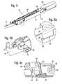
- FIG. 1 a shows a detailed detail of the perspective view of the door hinge 10 according to FIG. 1, which shows the region of the guide bolt 30 and the recess 32.
- the guide pin 30 is in the folded state at that stop in the recess 32, which faces away from the first pivot pin 16.
- the extension 58 of the cover 26 is shown enlarged in FIG. 1a. The extension 58 is in engagement with the displacement part 24, so that the displacement part 24 can not be displaced toward the pivot axis 16.
- FIG 2 shows a plan view of the preferred embodiment of the door hinge according to FIG 1.
- the compression spring 20 is, as well as the tension spring 22, not visible in FIG 2, in a relaxed state when the door hinge. 10 is in the folded state.
- FIG. 3 shows a side sectional view of the door hinge 10 along the sectional area A-A in FIG.
- the door hinge 10 is also in the folded state in FIG.
- the displacement part 24 is pivotally mounted on the second hinge part 14 via the second pivot pin 46.
- the second pivot pin 46 is located above the first pivot pin 16 and is slightly spaced therefrom. If the second hinge part 14 is folded around the pivot axis 16 relative to the hinge housing 18, the sliding part 24 is displaced within the hinge housing 18 along its longitudinal axis to the pivot axis 16.
- the compression spring 20 and the tension spring 22 are each formed as elongated coil springs.
- the longitudinal axes of the compression spring 20 and the tension spring 22 extend approximately parallel to the longitudinal axis of the first hinge part 12 and thus also parallel to the longitudinal axis of the hinge housing 18 and the sliding member 24.
- the compression spring 20 and the tension spring 22 are arranged one behind the other, wherein the compression spring 20th closer to the pivot axis 16 is located.
- the compression spring 20 is coupled to the hinge housing 18 and to the displacement part 24.
- the compression spring 20 is stabilized by a spring guide 36.
- the spring guide 36 comprises an elongate member and a stop.
- the elongated part of the spring guide 36 penetrates the Compression spring 20 in the longitudinal direction.
- the stop of the spring guide 36 is located on the pivot axis 16 facing away from the end of the spring guide 36.
- the stop of the spring guide 36 is coupled via a rocker 34 with the sliding part 24.
- the one end region of the spring guide 36 which faces the pivot axis 16, penetrates a guide 60.
- the guide 60 is fastened in the hinge housing 18 and forms a plain bearing for the spring guide 36.
- the guide 60 forms a stop for the compression spring 20.
- the compression spring 20 is thus clamped between the guide 60 and the stop of the spring guide 36.
- the pivot axis 16 facing the end of the compression spring 20 is applied via the guide 60 to the hinge housing 18.
- the remote from the pivot axis 16 end of the compression spring 20 is coupled via the rocker 34 with the displacement part 24.
- the rocker 34 is designed as a two-armed lever and riveted to the sliding part 24 pivotally.
- the stop of the spring guide 36 is pivotally mounted.
- a roller 40 is rotatably mounted.
- the bottom of the hinge housing 18 has a barrier 42 which is formed substantially ramp-shaped or wedge-shaped.
- the barrier 42 is provided for interaction with the roller 40.
- the barrier 42 has an oblique plane, a convex surface section and an approximately vertical plane.
- the oblique plane faces the pivot axis 16, while the vertical plane is arranged on the side of the barrier 42 facing away from the pivot axis 16.
- the convex surface portion which is partially complementary to the surface of the roller 40 is formed.
- the tension spring 22 connects the hinge housing 18 with the displacement part 24.
- the tension spring 22 is suspended on a first fastening bolt 54 and on a second fastening bolt 56.
- the first fastening bolt 54 is located on the side facing the first pivot pin 16 side of the tension spring 22 and is attached to the displacement part 24, for example screwed.
- the second fastening bolt 56 is located on the side facing away from the first pivot pin 16 side of the tension spring 22 and is attached to the hinge housing 18, for example screwed.
- a displacement of the sliding member 24 to the first pivot pin 16 out causes the tension spring 22 is extended and thus tensioned.
- Both the compression spring 20 and the tension spring 22 cause the displacement member 24 is pushed along its longitudinal axis relative to the hinge housing 18 of the pivot axis 16.
- the compression spring 20 and the tension spring 22 generate a torque in the pivot axis 16, which must be overcome in order to obtain a deployed state of the door hinge 10.
- FIG. 3a shows a detailed section of the lateral sectional view of the door hinge according to FIG. 2.
- the securing bolt 38 is located on the upper stop of the elongated hole 68 and in a recess in the displacement part 24.
- the locking bolt 38 is provided for example as a child safety. When the sliding member 24 is locked by the securing bolt 38, the door can only be opened by persons familiar with the function and position of the securing bolt 38.
- FIG 3b a further detailed section of the lateral sectional view of the door hinge according to FIG 3 is shown.
- the section shows in particular the rocker 34th
- the roller 40 When opening the door, the roller 40 must overcome the barrier 42.
- the force required to unfold the door hinge 10 and thus to open the door depends on the geometric configuration of the barrier 42, the diameter of the roller 40 and the spring constant of the compression spring 20.
- the closing pressure of the door is determined by the spring force of the compression spring 20.
- the door At a pivoting angle between the first hinge part 12 and the second hinge part 14 of about 90 ° to about 100 °, the door is automatically closed.
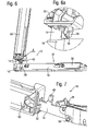
- FIG. 4 shows a further perspective view of the preferred embodiment of the door hinge 10 in a partially unfolded state.
- the angle between the first hinge part 12 and the second hinge part 14 in this state is approximately between 105 ° and 115 °.
- This is a stable condition in which the roller 40 is located in the convex surface portion of the barrier 42.
- the partially unfolded state according to FIG. 4 allows a stable position of the door between the fully open state and the closed state. Such a position is desirable and advantageous for many household appliances. This position can be used for example for cooling a cooking appliance or for defrosting a freezer.
- FIG 4a a detailed section of the perspective view of the door hinge 10 shown in FIG 4. 4a shows in particular the recess 32, the guide pin 30 and the extension 58.
- the guide pin 30 is located in a central region on the edge of the recess 32.
- FIG. 4b shows a detailed section of a sectional view of the door hinge 10 in the state according to FIG. 4, in which in particular the first pivot pin 16, the second pivot pin 46 and the securing bolt 38 are shown in detail.
- the securing bolt 38 is located at the lower stop of the elongated hole 68 in an unlocked state.
- FIG. 4 c shows a further detailed section of a sectional view of the door hinge in the state according to FIG. 4. 4c shows how the roller 40 is engaged with the convex surface portion of the barrier 42. This allows the stable, partially unfolded state of the door hinge 10 and thus a stable intermediate position of the door of the household appliance.
- FIG 5 is a perspective view of the preferred embodiment of the door hinge 10 is shown in an unfolded state.
- the angle between the first hinge part 12 and the second hinge part 14 is slightly less than 180 °.
- the guide pin 30 is located at that stop in the recess 32, which faces the pivot pin 16.
- the compression spring 20 is in a compressed and thus tensioned state.
- the tension spring 22, which is not visible in FIG. 5, is in a stretched and thus likewise in a tensioned state.
- the securing bolt 38 is located at the lower stop of the slot 68 and thus in the unlocked state.
- FIG 5a shows a detailed section of the perspective view of the door hinge 10 in the unfolded state shown in FIG 5, in which the recess 32 and the guide pin 30 are shown enlarged.
- the guide pin 30 is located on that stop of the recess 32, which faces the pivot axis 16.
- FIG. 5 b shows a further detailed section of the perspective view of the door hinge 10 in the unfolded state according to FIG. 5, which shows the region of the pivot pin 16 and the fastening lever 28.
- 5C shows a detailed section of a sectional view of the door hinge 10 in the unfolded state according to FIG. 5.
- the detail shows the area of the rocker 34 and clarifies the position and position of the rocker 34 relative to the barrier 42 when the door hinge 10 is in the unfolded state located.
- the roller 40 is on the sloping surface portion of the barrier 42, the door is approximately in equilibrium.
- the second hinge part 14 is in a frame part 50 attached.
- the frame part 50 is for example a part of a door of a household appliance.
- the frame part 50 comprises a channel which is provided for receiving the second hinge part 14.
- the second hinge part 14 is inserted up to the stop 48 in the channel of the frame part 50.
- a hook 52 is at the pivot pin 16 facing end side of the frame part 50 to which the fastening lever 28 is locked. In this way, the frame member 50 and thus the door to the door hinge 10 is easy to fasten.
- FIG. 6a shows a detailed section of the perspective view of the door hinge according to FIG. 6, in which the hook 52 and the fastening lever 28 are shown enlarged. This figure illustrates how with simple means door is reliably fastened to the door hinge 10.
- Figure 7 is a perspective view of the application example of the door hinge shown in FIG 6, wherein the door hinge 10 is in the unfolded state.
- the second hinge part 14 is not completely inserted into the frame part 50.
- the end face of the frame part 50 is slightly spaced from the stop 48.
- the hook 52 and the fastening lever 28 are unlocked from each other.
- the door is first opened.
- the fastening lever 28 is thereby accessible to the user and is deflected towards the hinge housing 18.
- the door can be removed from the second hinge parts 14.
- the door is mounted in the reverse way.
- the rocker 34 may also be coupled to the tension spring 22 or an additional tension spring. In this way, the rolling friction resistance of the roller 40 can be increased.
- the sliding part can be provided for other functions.
- the sliding part depending on a particular position of the door, the switching on an electrical load, such as lighting, heating, a turbomachine such as a fan or a pump and / or a motor cause. It is also possible to activate a drive for automatically opening and closing the door at a certain position of the sliding part.
- the door hinge 10 is characterized in particular by its compact design.
- the door hinge 10 In the folded state, the door hinge 10 is formed substantially L-shaped, wherein the first hinge part 12 and the second hinge part 14 form the two legs.
- the door hinge 10 In the unfolded state, the door hinge 10 forms an elongated rod-shaped part.
- the door hinge 10 is mounted in a simple manner with standard fasteners on the housing of the household appliance. During assembly, no mechanical stresses must be overcome, which are generated by springs or the like. It is only the hinge housing 18 to be mounted on the housing of the household appliance and then to attach the door of the household appliance to the second hinge part 14.
Landscapes
- Engineering & Computer Science (AREA)
- Mechanical Engineering (AREA)
- Chemical & Material Sciences (AREA)
- Combustion & Propulsion (AREA)
- General Engineering & Computer Science (AREA)
- Closing And Opening Devices For Wings, And Checks For Wings (AREA)
- Hinges (AREA)
Applications Claiming Priority (1)
| Application Number | Priority Date | Filing Date | Title |
|---|---|---|---|
| DE200510002822 DE102005002822B4 (de) | 2005-01-20 | 2005-01-20 | Türscharnier für ein Haushaltsgerät |
Publications (2)
| Publication Number | Publication Date |
|---|---|
| EP1703053A2 true EP1703053A2 (fr) | 2006-09-20 |
| EP1703053A3 EP1703053A3 (fr) | 2013-04-03 |
Family
ID=36190587
Family Applications (1)
| Application Number | Title | Priority Date | Filing Date |
|---|---|---|---|
| EP05025514A Withdrawn EP1703053A3 (fr) | 2005-01-20 | 2005-11-23 | Charnière pour un appareil ménager |
Country Status (2)
| Country | Link |
|---|---|
| EP (1) | EP1703053A3 (fr) |
| DE (1) | DE102005002822B4 (fr) |
Cited By (3)
| Publication number | Priority date | Publication date | Assignee | Title |
|---|---|---|---|---|
| EP2372059A1 (fr) * | 2010-03-31 | 2011-10-05 | Electrolux Home Products Corporation N.V. | Dispositif de charnière de porte pour cavité de four d'un four de cuisson |
| US8256064B2 (en) | 2007-02-19 | 2012-09-04 | Liebherr-Hausgeraete Ochsenhausen Gmbh | Refrigerator and/or freezer with hinge |
| EP2191088B2 (fr) † | 2007-09-07 | 2017-03-29 | Hettich-ONI GmbH & Co. KG | Charnière de porte d' appareil ménager |
Families Citing this family (5)
| Publication number | Priority date | Publication date | Assignee | Title |
|---|---|---|---|---|
| IT1393614B1 (it) * | 2009-04-08 | 2012-05-08 | Nuova Star Spa | Cerniera per ante o sportelli |
| DE102010002097A1 (de) * | 2010-02-18 | 2011-08-18 | BSH Bosch und Siemens Hausgeräte GmbH, 81739 | Haushaltsgerät, insbesondere Garofen |
| DE102013001402B4 (de) * | 2013-01-28 | 2016-06-09 | Apparatebau Gronbach GmbH | Scharnier für einen Herd sowie Herd |
| WO2015027515A1 (fr) * | 2013-09-02 | 2015-03-05 | Xiao Yousong | Charnière |
| IT201800007641A1 (it) * | 2018-07-30 | 2020-01-30 | Cmi Cerniere Mecc Industriali Srl | Dispositivo a cerniera compatta |
Citations (1)
| Publication number | Priority date | Publication date | Assignee | Title |
|---|---|---|---|---|
| DE2025542A1 (de) | 1970-05-26 | 1972-04-13 | Licentia Gmbh | Bratraumtüre für Herde |
Family Cites Families (8)
| Publication number | Priority date | Publication date | Assignee | Title |
|---|---|---|---|---|
| DE1127247B (de) * | 1958-10-07 | 1962-04-05 | Steinbach & Vollmann | Scharnier mit gewichtsausgleichender Feder |
| US4021968A (en) * | 1976-05-14 | 1977-05-10 | Kendall Willard E | Counterbalancing hinge for range oven doors or the like |
| US4817240A (en) * | 1983-06-03 | 1989-04-04 | Ace Manufacturing Co. | Appliance door hinge |
| IT1242647B (it) * | 1990-05-17 | 1994-05-16 | Cmi Cerniere Mecc Ind | Perfezionamenti alle cerniere per l'apertura e chiusura a mezzi a forze autoequilibranti di portelli particolarmente i ndicate per portelli frontali ad articolazione ad asse orizzontale di apparecchiature elettrodomestiche. |
| US5025776A (en) * | 1990-05-18 | 1991-06-25 | The Stanley Works | Door mounted hinge for oven doors and the like |
| IT238944Y1 (it) * | 1995-04-12 | 2001-02-19 | Cmi Srl | Dispositivo di cerniera perfezionato in particolare per il portellodi apparecchi elettrodomestici e simili |
| IT1292053B1 (it) * | 1997-05-30 | 1999-01-25 | Brera Cerniere Srl | Cerniera per sportelli di forni per cucine elettriche,a gas,a microonde o simili |
| DE19923994A1 (de) * | 1999-05-26 | 2000-11-30 | Bsh Bosch Siemens Hausgeraete | Hausgerät-Scharniervorrichtung |
-
2005
- 2005-01-20 DE DE200510002822 patent/DE102005002822B4/de not_active Expired - Fee Related
- 2005-11-23 EP EP05025514A patent/EP1703053A3/fr not_active Withdrawn
Patent Citations (1)
| Publication number | Priority date | Publication date | Assignee | Title |
|---|---|---|---|---|
| DE2025542A1 (de) | 1970-05-26 | 1972-04-13 | Licentia Gmbh | Bratraumtüre für Herde |
Cited By (3)
| Publication number | Priority date | Publication date | Assignee | Title |
|---|---|---|---|---|
| US8256064B2 (en) | 2007-02-19 | 2012-09-04 | Liebherr-Hausgeraete Ochsenhausen Gmbh | Refrigerator and/or freezer with hinge |
| EP2191088B2 (fr) † | 2007-09-07 | 2017-03-29 | Hettich-ONI GmbH & Co. KG | Charnière de porte d' appareil ménager |
| EP2372059A1 (fr) * | 2010-03-31 | 2011-10-05 | Electrolux Home Products Corporation N.V. | Dispositif de charnière de porte pour cavité de four d'un four de cuisson |
Also Published As
| Publication number | Publication date |
|---|---|
| DE102005002822B4 (de) | 2009-11-26 |
| EP1703053A3 (fr) | 2013-04-03 |
| DE102005002822A1 (de) | 2006-08-03 |
Similar Documents
| Publication | Publication Date | Title |
|---|---|---|
| EP2096360B1 (fr) | Porte d'appareil ménager | |
| DE9406891U1 (de) | Klapp-Schwing-Dachfenster mit Ausstellhilfe | |
| EP3621483B1 (fr) | Dispositif de retenue pour façade de tiroir | |
| EP2362050A2 (fr) | Dispositif de charnière, appareil ménager doté d'une porte et procédé de rééquipement d'un amortisseur | |
| WO2018033221A1 (fr) | Charnière de meuble | |
| DE29522288U1 (de) | Möbelscharnier | |
| EP1605796A1 (fr) | Tiroir | |
| EP1703053A2 (fr) | Charnière pour un appareil ménager | |
| EP3621482B1 (fr) | Dispositif de retenue destiné à une façade de tiroir | |
| EP3045634B1 (fr) | Dispositif orientable pour une fenetre ou une porte comprenant un dispositif de stockage d'energie | |
| DE69811040T2 (de) | Türschliessvorrichtung für ein Haushaltsgerät, beispielsweise eine Geschirrspülmaschine | |
| DE10152699B4 (de) | Möbelscharnier mit Öffnungsmechanik, insbesondere für Möbeltüren | |
| EP3183408B1 (fr) | Élément de commande pour système de ferrure | |
| DE9403746U1 (de) | Vorrichtung zum Öffnen und Schließen von Toren | |
| EP3056640B1 (fr) | Charniere pivotante pour une fenetre, en particulier fenetre de toit d'habitation | |
| WO2020169245A1 (fr) | Fenêtre pour un véhicule ou un conteneur comprenant un mécanisme de verrouillage | |
| DE10058483B4 (de) | Selbst sperrende Verriegelungseinrichtung für Flügel mit Überschlag | |
| DE19603748C1 (de) | Verschluß für Schranktüren in Form von Schiebetüren oder Rolladen | |
| DE3243865C2 (de) | Türscharnier für Haushaltgeräte | |
| EP1614844A2 (fr) | Dispositif d'articulation | |
| EP2096361B1 (fr) | Porte d'appareil ménager et procédé de commande d'une porte d'appareil ménager | |
| AT402652B (de) | Ladenhalter für fenster- oder türläden ladenhalter für fenster- oder türläden | |
| EP3211165A1 (fr) | Dispositif d'ouverture d'un vantail oscillo-battant d'une fenêtre ou d'une porte destiné au basculement motorisé et à la rotation et au basculement manuels | |
| DE102005007831A1 (de) | Motorisch antreibbare oder angetriebene Scherenanordnung | |
| DE10239890A1 (de) | Türverriegelung |
Legal Events
| Date | Code | Title | Description |
|---|---|---|---|
| PUAI | Public reference made under article 153(3) epc to a published international application that has entered the european phase |
Free format text: ORIGINAL CODE: 0009012 |
|
| AK | Designated contracting states |
Kind code of ref document: A2 Designated state(s): AT BE BG CH CY CZ DE DK EE ES FI FR GB GR HU IE IS IT LI LT LU LV MC NL PL PT RO SE SI SK TR |
|
| AX | Request for extension of the european patent |
Extension state: AL BA HR MK YU |
|
| RAP1 | Party data changed (applicant data changed or rights of an application transferred) |
Owner name: ELECTROLUX HOME PRODUCTS CORPORATION N.V. |
|
| RAP1 | Party data changed (applicant data changed or rights of an application transferred) |
Owner name: ELECTROLUX HOME PRODUCTS CORPORATION N.V. |
|
| RIC1 | Information provided on ipc code assigned before grant |
Ipc: E05D 5/02 20060101AFI20130111BHEP Ipc: E05D 11/10 20060101ALI20130111BHEP Ipc: E05F 1/12 20060101ALI20130111BHEP Ipc: F24C 15/02 20060101ALI20130111BHEP |
|
| PUAL | Search report despatched |
Free format text: ORIGINAL CODE: 0009013 |
|
| AK | Designated contracting states |
Kind code of ref document: A3 Designated state(s): AT BE BG CH CY CZ DE DK EE ES FI FR GB GR HU IE IS IT LI LT LU LV MC NL PL PT RO SE SI SK TR |
|
| AX | Request for extension of the european patent |
Extension state: AL BA HR MK YU |
|
| RIC1 | Information provided on ipc code assigned before grant |
Ipc: E05D 11/10 20060101ALI20130226BHEP Ipc: E05F 1/12 20060101ALI20130226BHEP Ipc: E05D 5/02 20060101AFI20130226BHEP Ipc: F24C 15/02 20060101ALI20130226BHEP |
|
| 17P | Request for examination filed |
Effective date: 20131002 |
|
| RBV | Designated contracting states (corrected) |
Designated state(s): AT BE BG CH CY CZ DE DK EE ES FI FR GB GR HU IE IS IT LI LT LU LV MC NL PL PT RO SE SI SK TR |
|
| AKX | Designation fees paid |
Designated state(s): AT BE BG CH CY CZ DE DK EE ES FI FR GB GR HU IE IS IT LI LT LU LV MC NL PL PT RO SE SI SK TR |
|
| GRAP | Despatch of communication of intention to grant a patent |
Free format text: ORIGINAL CODE: EPIDOSNIGR1 |
|
| INTG | Intention to grant announced |
Effective date: 20140102 |
|
| STAA | Information on the status of an ep patent application or granted ep patent |
Free format text: STATUS: THE APPLICATION IS DEEMED TO BE WITHDRAWN |
|
| 18D | Application deemed to be withdrawn |
Effective date: 20140513 |