EP0388801A2 - Dispositif de levage hydraulique - Google Patents
Dispositif de levage hydraulique Download PDFInfo
- Publication number
- EP0388801A2 EP0388801A2 EP90104950A EP90104950A EP0388801A2 EP 0388801 A2 EP0388801 A2 EP 0388801A2 EP 90104950 A EP90104950 A EP 90104950A EP 90104950 A EP90104950 A EP 90104950A EP 0388801 A2 EP0388801 A2 EP 0388801A2
- Authority
- EP
- European Patent Office
- Prior art keywords
- lifting
- vehicle
- lifting device
- lifting cylinder
- arms
- Prior art date
- Legal status (The legal status is an assumption and is not a legal conclusion. Google has not performed a legal analysis and makes no representation as to the accuracy of the status listed.)
- Withdrawn
Links
- 238000006073 displacement reaction Methods 0.000 description 2
- 239000012530 fluid Substances 0.000 description 2
- 230000000087 stabilizing effect Effects 0.000 description 2
- 230000006978 adaptation Effects 0.000 description 1
- 230000005540 biological transmission Effects 0.000 description 1
- 230000005484 gravity Effects 0.000 description 1
- 238000003780 insertion Methods 0.000 description 1
- 230000037431 insertion Effects 0.000 description 1
- 235000000396 iron Nutrition 0.000 description 1
- 238000004519 manufacturing process Methods 0.000 description 1
- 239000000725 suspension Substances 0.000 description 1
Images
Classifications
-
- A—HUMAN NECESSITIES
- A01—AGRICULTURE; FORESTRY; ANIMAL HUSBANDRY; HUNTING; TRAPPING; FISHING
- A01D—HARVESTING; MOWING
- A01D34/00—Mowers; Mowing apparatus of harvesters
- A01D34/01—Mowers; Mowing apparatus of harvesters characterised by features relating to the type of cutting apparatus
- A01D34/412—Mowers; Mowing apparatus of harvesters characterised by features relating to the type of cutting apparatus having rotating cutters
- A01D34/63—Mowers; Mowing apparatus of harvesters characterised by features relating to the type of cutting apparatus having rotating cutters having cutters rotating about a vertical axis
- A01D34/64—Mowers; Mowing apparatus of harvesters characterised by features relating to the type of cutting apparatus having rotating cutters having cutters rotating about a vertical axis mounted on a vehicle, e.g. a tractor, or drawn by an animal or a vehicle
- A01D34/66—Mowers; Mowing apparatus of harvesters characterised by features relating to the type of cutting apparatus having rotating cutters having cutters rotating about a vertical axis mounted on a vehicle, e.g. a tractor, or drawn by an animal or a vehicle with two or more cutters
- A01D34/661—Mounting means
- A01D34/662—Mounting means to the front of the vehicle
-
- A—HUMAN NECESSITIES
- A01—AGRICULTURE; FORESTRY; ANIMAL HUSBANDRY; HUNTING; TRAPPING; FISHING
- A01D—HARVESTING; MOWING
- A01D34/00—Mowers; Mowing apparatus of harvesters
- A01D34/01—Mowers; Mowing apparatus of harvesters characterised by features relating to the type of cutting apparatus
- A01D34/412—Mowers; Mowing apparatus of harvesters characterised by features relating to the type of cutting apparatus having rotating cutters
- A01D34/63—Mowers; Mowing apparatus of harvesters characterised by features relating to the type of cutting apparatus having rotating cutters having cutters rotating about a vertical axis
- A01D34/64—Mowers; Mowing apparatus of harvesters characterised by features relating to the type of cutting apparatus having rotating cutters having cutters rotating about a vertical axis mounted on a vehicle, e.g. a tractor, or drawn by an animal or a vehicle
- A01D2034/645—Lifting means for the cutter of the lawnmower mounted at the front of the vehicle for inspection and maintenance
-
- A—HUMAN NECESSITIES
- A01—AGRICULTURE; FORESTRY; ANIMAL HUSBANDRY; HUNTING; TRAPPING; FISHING
- A01D—HARVESTING; MOWING
- A01D2101/00—Lawn-mowers
Definitions
- the invention relates to a hydraulically actuated lifting device for a vehicle with a first and a second with a mutually spaced lifting arm, which are pivotally connected at one end to the vehicle and extend outward from their connection point on the vehicle to connections for a device.
- a lifting cylinder is assigned to each lifting arm, and the device is designed as a lawn mower connected to a garden tractor on the front.
- the lawn mower When pressurized, the lawn mower can be lifted out of its working position and moved to a position in which small obstacles such as curbs etc. can be easily overcome.
- the hydraulic circuit for the two lifting cylinders connected in parallel is also designed so that a part of the implement weight can be transferred to the garden tractor when the lawnmower is in the working position.
- two lifting cylinders require a more complex hydraulic circuit and increase the costs for the entire hydraulic system.
- the object to be achieved with the invention is seen in making the known lifting device more advantageous and taking precautions in the event that the device weight should not be evenly distributed over the two lifting arms.
- the lifting arms are height-adjustable via a single lifting cylinder, the lifting arms at one end interconnecting cross part, can be connected at the other end to the vehicle and is longitudinally adjustable with respect to the cross part.
- a compact hydraulic system is created, which is cheaper to manufacture and provides devices by means of which the single lifting cylinder can be transversely adjusted if the weight of the device should not be evenly distributed over the two lifting arms. Because only with a uniform weight distribution on the lifting arms is it possible to work properly in a floating position, i.e. when part of the weight of the device is transferred to the vehicle, which is particularly desirable if the device connected to the lifting device is one Lawnmowers are where a constant cutting height is important.
- a bracket for receiving the one end of the lifting cylinder is arranged on the frame of the vehicle such that it is adjustable parallel to the transverse part, the other end of the lifting cylinder being seen on one of several in the longitudinal direction of the transverse part juxtaposed and provided on the cross member connection points can be connected.
- the lifting cylinder can expediently be accommodated in the console such that it can pivot about a first axis.
- the frame of the vehicle is slotted.
- a screw that is also passed through the console is inserted into this slot and secured from the outside by a nut, after loosening the console can be easily adjusted.
- the slot can have a widened end for easy insertion of the screw head.
- the ends of the cross part are connected to the lifting arms in such a way that each lifting arm can perform a vertically directed relative movement with respect to the other.
- the lifting cylinder follows the path of the connected device when adjusting the height, it is further proposed according to the invention that the lifting cylinder is connected to the transverse part via a swivel joint.
- the transverse part can advantageously be designed as a rod with a multiplicity of bores for receiving a peg belonging to the swivel joint and optionally insertable into one of the bores.
- the lifting arms can diverge from a preselected, approximately central location to the connections for the device, and the ends of the cross member can be connected to the lifting arms via brackets in the region of the preselected location.
- the adjustability of the console can also be achieved in that the console is displaceable on a hollow support of the frame and rotatably receives one end of the lifting cylinder in a swivel tube which is firmly connected to the console.
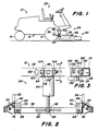
- Fig. 1 of the drawing 10 denotes a vehicle in the form of a garden tractor, which has front drive wheels 12 and rear steerable wheels 14 which carry a frame 16.
- a device 20 - in the exemplary embodiment a lawn mower - is connected to the front of the vehicle 10 via a lifting device 24.
- the lifting device can be actuated from an operator station 28 provided on the front of the vehicle 10, which also contains further operating elements required for operating the vehicle and the connected device.
- the lifting device 24 has a first and a second lifting arms 32 and 34 which are arranged at a transverse distance from one another and which pivotally engage the frame 16 of the vehicle 10 at connection points 36.
- the latter are located in the area of the front axle and allow the height of the lifting arms 32 and 34 to be adjusted about horizontal transverse axes. From their connection points 36, the lifting arms 32 and 34 extend forward to kink points 42, from which the lifting arms 32, 34 extend diverging further forward.
- the front ends of the lifting arms 32, 34 pivotally engage connections 46 which engage at a mutual transverse distance the top of the device 20 are provided.
- a stabilizing rod 48 is provided in the area of a connection point 36 at one end and at the other end on the opposite lifting arm 32 or 34.
- the lifting device 24 is equipped with a single, transversely adjustable lifting cylinder 54.
- This lifting cylinder 54 is pivotally connected to the frame 16 with its cylinder-side end, namely below the operator station 28 at the front end of the vehicle 10.
- the piston rod-side end of the lifting cylinder 54 engages approximately in the middle of a rod-shaped cross member 56, which in turn is between the Bends 42 extends on the lifting arms 32, 34.
- the attachment takes place via brackets 62 and 64 designed as angle irons, which are connected to the kinks 42 via screws 66 and have inwardly directed legs 72 and 74 with openings which extend to oblong holes 76 and 78 in the two ends of the transverse part 56 are aligned.
- Lockers 82 and 84 are guided through the corresponding openings in the legs 72, 74 of the brackets 62, 64 and the elongated holes 76, 78 and position the transverse part 56 between the kinks 42, 44 on the lifting arms 32 and 34.
- the elongated holes 76 and 78 enable a relative movement between the brackets 62 and 64 and the corresponding ends of the cross member 56, and the connection selected in this way leads to an independent vertical movement of the two lifting arms 32 and 34.
- the stabilizing rod 48 can have an upper opening in one of the legs 72 or 74 get connected.
- the cross member 56 is provided with a plurality of side-by-side openings 86 which can optionally receive a pin 88 which extends through a swivel 92 which is connected to the lower end of the piston rod of the lifting cylinder 54.
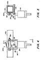
- the lifting cylinder 54 has a cylinder-side connection 94, which consists of two upwardly directed and drilled eyelets 96. These are pivotally received by a bow-shaped and transversely adjustable bracket 100 such that they can pivot about a transverse axis.
- the console 100 shown in FIGS. 2 and 3 has a forwardly opening U-shaped bracket 102 with drilled legs 104 which surround the eyelets 96 from the outside.
- a pivot pin 108 is passed through the bores in the eyelets 96 and in the legs 104 and thus connects the lifting cylinder 54 to the bracket 100 or its bracket 102 in a vertically pivotable manner.
- the web part 112 of the U-shaped bracket 102 is connected to an end face of a transverse hollow beam 116, which is part of the frame 16 of the vehicle 10.
- An elongated hole 120 is machined into the end face of the hollow support 116 in such a way that its long axis runs horizontally, one end 122 of the elongated hole 120 still being drilled out.
- the bracket 102 of the bracket 100 is displaceably and rotatably connected to the end face of the hollow support 116 via a screw connection 126.
- the screw connection 126 consists in detail of a screw 128 with a head 132 which is inserted into the hollow support 116 through the drilled end 122 of the elongated hole 120.
- the screw 128 then extends from its head 132 located in the hollow support 116 through a bush 134 and a bore in the web part 112. From the outside, the screw connection 126 is secured via a nut 136 which is tightened against the bush 134 and the bracket 102 secures in a position that corresponds to the weight distribution to the stroke poor 32, 34 is selected.
- the bracket 102 can rotate about the longitudinal axis of the screw 128 if the lower connection point of the lifting cylinder 54 is not aligned with its upper one.
- the adjustable console is designated 100a and consists in particular of a downwardly open U-shaped bracket 142 which is displaceable, engages over a hollow support 116a from above and is secured by a screw 146 which is secured in one with the lower end of the bracket 142 welded nut 148 can be screwed.
- a transverse pivot tube 152 is also welded to the end face of the bracket 142 above the nut 148, which can be stiffened via a strut 156.
- the strut 156 is also welded to the swivel tube 152 and the U-shaped bracket 142 for this purpose.
- the screw 146 is tightened accordingly so that the bracket 142 fits well on the hollow support 116a and at the same time its displacement on the hollow support 116a is possible after loosening the screw 148.
- the lifting cylinder 54 is pivotally connected to the bracket 100a or its bracket 142 via a pivot pin 158 which extends through the pivot tube 152 and through bores in the eyelets 96 at the end on the cylinder side. The lifting cylinder 54 is thus displaceably arranged on the hollow support 116a and can be aligned with one of the bores 86 in the transverse part 56.
- the lifting cylinder 54 is integrated in a hydraulic circuit, not shown, and can be acted upon with pressure fluid via an actuating member provided at the control station 28 in order to cause the lifting arms 32, 34 to pivot.
- the connected device 20 can then be raised or lowered depending on the actuation the.
- the lifting cylinder 54 can be operated so that part of the weight of the device can be transferred to the vehicle 10.
- a corresponding hydraulic circuit with a control valve is shown in European patent application No. 90102758.1, to which reference is expressly made here.
- the pin 88 is inserted into the central bore 86 on the cross member 56 and the bracket 102 is fixed at a location above this bore.
- the transverse part 56 is pivoted up and consequently the two lifting arms 32, 34 together until the device 20 reaches its transport position.
- the piston rod By extending the piston rod, the device 20 is lowered, the lifting arms 32, 34 being adjusted downwards together with the transverse part 56.
- the elongated holes 76 and 78 in the cross member 56 allow the vertical adjustment of the lifting arms 32, 34 so that the device can follow the ground contour.
- a floating position of the device is achieved when hydraulic fluid is applied to the lifting cylinder in such a way that the piston rod wants to retract, but without actually lifting the device 20 off the floor.
- the arrangement and design of the cross member 56 then enables the weight distribution or weight transmission on the lifting arms 32, 34 to remain the same even in this position. If the operator determines that the device 20 does not lift out evenly or that one side in the floating position receives more pressure than the other side, then the operator need only loosen the nut 136 and the pin in the embodiment according to FIGS. 2 and 3 To remove 88 from the corresponding bore 86 in the cross member 56, after which the lifting cylinder 54 can be adjusted transversely as far as necessary.
- the operator determines that the lifting arm 32 is raised later than the lifting arm 34 and is lowered first, then it only has to push the lifting cylinder closer to the lifting arm 32, whereby the latter receives more pressure and the lifting arm 34 receives less pressure, so that ultimately again an even weight distribution is created.
- the swivel joint 92 at the end of the lifting cylinder 54 on the piston rod side is then connected again to the transverse part 56 by inserting the pin 88 into the selected bore 86.
- the U-shaped bracket 102 is then moved laterally in the region of the elongated hole 120 until the lifting cylinder 54 assumes an essentially upright position. Thereafter, the nut 136 must still be tightened to determine the bracket 102.
- the bracket 142 can be moved on the hollow carrier 116a.
- the swivel joint 92 on the piston rod end and the rotatable suspension of the cylinder end of the lifting cylinder 54 allow the cross member 56 and with it the connected device 20 to be displaced transversely to the frame 16 within certain limits.
- the elongated holes 76 and 78 enable individual dodging in the vertical direction, so that the lifting device 24 fulfills all the requirements for an even weight distribution, floating position and adaptation to the ground contour for a device which is controlled by a single lifting cylinder.
- a lawn mower can be provided as the device. But the lifting device can be used equally well with other floor care equipment.
Landscapes
- Life Sciences & Earth Sciences (AREA)
- Environmental Sciences (AREA)
- Harvester Elements (AREA)
- Lifting Devices For Agricultural Implements (AREA)
- Forklifts And Lifting Vehicles (AREA)
Applications Claiming Priority (2)
| Application Number | Priority Date | Filing Date | Title |
|---|---|---|---|
| US327280 | 1989-03-22 | ||
| US07/327,280 US4896489A (en) | 1989-03-22 | 1989-03-22 | Implement lift and flotation system with a single transversely adjustable cylinder |
Publications (2)
| Publication Number | Publication Date |
|---|---|
| EP0388801A2 true EP0388801A2 (fr) | 1990-09-26 |
| EP0388801A3 EP0388801A3 (fr) | 1992-07-08 |
Family
ID=23275903
Family Applications (1)
| Application Number | Title | Priority Date | Filing Date |
|---|---|---|---|
| EP19900104950 Withdrawn EP0388801A3 (fr) | 1989-03-22 | 1990-03-16 | Dispositif de levage hydraulique |
Country Status (3)
| Country | Link |
|---|---|
| US (1) | US4896489A (fr) |
| EP (1) | EP0388801A3 (fr) |
| CA (1) | CA2010858A1 (fr) |
Families Citing this family (14)
| Publication number | Priority date | Publication date | Assignee | Title |
|---|---|---|---|---|
| US5203250A (en) * | 1990-12-21 | 1993-04-20 | Deere & Company | Fluid cylinder mechanism |
| US5515669A (en) * | 1995-02-03 | 1996-05-14 | The Shivvers Group, Inc. | Anti-buck device for out-front mower tractors |
| US5784867A (en) * | 1995-10-03 | 1998-07-28 | Shivvers Incorporated | Variable force traction enhance systems |
| DE29803077U1 (de) * | 1998-02-24 | 1998-06-25 | Hermann Kirchner GmbH & Co KG, 36251 Bad Hersfeld | Zusatzeinrichtung für einen Fertiger |
| ITPD20010058U1 (it) * | 2001-07-06 | 2003-01-06 | Antonio Carraro Spa | Struttura perfezionata di attrezzatura di sollevamento dell'utensile per veicoli da giardinaggio tipo tagliaerba o simili. |
| US6928798B2 (en) * | 2004-01-02 | 2005-08-16 | Textron Inc. | Swing out arm for rear rotary deck |
| US7975407B2 (en) * | 2006-08-31 | 2011-07-12 | Mibar Products Ltd. | Plow systems for non-highway vehicles |
| US7475530B2 (en) * | 2007-03-02 | 2009-01-13 | Textron Inc. | Articulating swing-out arm |
| US20120023882A1 (en) * | 2007-09-27 | 2012-02-02 | Ariens Company | Universal mounting structure for a lawn striper |
| US8333096B2 (en) * | 2009-09-21 | 2012-12-18 | Shape Corp. | Method of forming three-dimensional multi-plane beam |
| USD877208S1 (en) | 2015-10-14 | 2020-03-03 | Brandon L. Bungart | Welded-on teeth for a front-end, soil-leveling attachment removably attached to a skid steer |
| USD865819S1 (en) | 2015-10-14 | 2019-11-05 | Donnie Bungart | Replaceable tooth for a front-end, soil-leveling attachment removably attached to a skid steer |
| USD879158S1 (en) | 2015-10-14 | 2020-03-24 | Brandon L. Bungart | Mounting frame carrying an array of soil-raking teeth and carried by a front-end, soil-leveling attachment removably attached to a skid steer |
| US11903340B1 (en) | 2017-02-28 | 2024-02-20 | Brandon L. Bungart | Hookup designs for attachments to skid steer loaders and the like |
Family Cites Families (11)
| Publication number | Priority date | Publication date | Assignee | Title |
|---|---|---|---|---|
| US2210907A (en) * | 1938-02-16 | 1940-08-13 | Minneapolis Moline Power Co | Power lift tractor hitch |
| US2477994A (en) * | 1943-10-15 | 1949-08-02 | Jabez A Love | Implement hitch for tractors |
| US2590011A (en) * | 1948-09-02 | 1952-03-18 | Jesse C Hawkins | Hydraulically operated lift for tractors |
| US2658438A (en) * | 1950-07-11 | 1953-11-10 | James H Seng | Tractor mounting for agricultural implements |
| GB825741A (en) * | 1954-12-15 | 1959-12-23 | John Mcconachie Rollo | Improvements in or relating to agricultural implements |
| US3031175A (en) * | 1958-04-10 | 1962-04-24 | Darrel M Wooldridge | Ripper mounting for twin crawlers |
| US4175765A (en) * | 1978-05-15 | 1979-11-27 | Dura Corporation | Parallel hitch for a belly mounted tractor appliance |
| US4307561A (en) * | 1980-01-23 | 1981-12-29 | Outboard Marine Corporation | Blade housing lift for riding mower |
| US4487268A (en) * | 1983-01-31 | 1984-12-11 | Greve Lester B | Lifting attachments for cultivators |
| JPS62181706A (ja) * | 1986-02-04 | 1987-08-10 | 株式会社クボタ | フロントマウント作業機の装着装置 |
| US4747257A (en) * | 1986-05-13 | 1988-05-31 | Deere & Company | Weight transfer control for a front mount mower |
-
1989
- 1989-03-22 US US07/327,280 patent/US4896489A/en not_active Expired - Lifetime
-
1990
- 1990-02-23 CA CA002010858A patent/CA2010858A1/fr not_active Abandoned
- 1990-03-16 EP EP19900104950 patent/EP0388801A3/fr not_active Withdrawn
Also Published As
| Publication number | Publication date |
|---|---|
| EP0388801A3 (fr) | 1992-07-08 |
| CA2010858A1 (fr) | 1990-09-22 |
| US4896489A (en) | 1990-01-30 |
Similar Documents
| Publication | Publication Date | Title |
|---|---|---|
| DE69113095T2 (de) | Landwirtschaftliche Maschine mit einer Vorrichtung zur Ermittlung der Zwischenstellung des Verbindungsmittels. | |
| EP0924975B1 (fr) | Outil pour ameublir le sol en profondeur | |
| DE2737053A1 (de) | Landwirtschaftlich nutzbares arbeitsgeraet | |
| DE2838829A1 (de) | Mehrschariger aufsattelpflug | |
| EP0388801A2 (fr) | Dispositif de levage hydraulique | |
| EP0063774A1 (fr) | Système d'attelage pour un tracteur agricole | |
| DE3004576A1 (de) | Kombinatsgeraet zur bodenbearbeitung | |
| DE2808354C2 (fr) | ||
| DE3529517C2 (de) | Pflug | |
| EP4104654B1 (fr) | Appareil de traitement du sol à protection hydraulique contre les surcharges | |
| DE3523632A1 (de) | Pflug | |
| DE3530107C2 (de) | Pflug | |
| DE2838828C2 (de) | Mehrschariger Aufsattelpflug | |
| DE68929086T2 (de) | Mähmaschine | |
| DE68920222T2 (de) | Vorrichtung zum Schneiden von Rillen in den Boden. | |
| DE69419341T2 (de) | Bodenbearbeitungsmaschine | |
| DE1455578C3 (de) | Steuervorrichtung für Ackerschlepper mit einem Dreipunktgestänge sowie einem hydraulischen Kraftheber | |
| DE2220585C3 (de) | Regtungsvorrichtung zur Vertikalverstellung eines an die Kraftheberanlage eines Schleppers angeschlossenen Bodenbearbeitungsgerätes | |
| DE2701117C2 (de) | Vorrichtung zum Einsteuern der Arbeitshöhe von landwirtschaftlichen Geräten, insbesondere von Arbeitswerkzeugen an Rübenerntemaschinen | |
| DE3139936C2 (fr) | ||
| DE4031504C2 (de) | Aufsatteldrehpflug mit variabler Arbeitsbreiteneinstellung | |
| DE3218525A1 (de) | Boeschungsmaehgeraet | |
| EP0259801B1 (fr) | Dispositif d'attelage pour tracteur agricole | |
| EP0562176B1 (fr) | Charrue semiportée ou tractée | |
| EP3620038A1 (fr) | Cultivateur tracté |
Legal Events
| Date | Code | Title | Description |
|---|---|---|---|
| PUAI | Public reference made under article 153(3) epc to a published international application that has entered the european phase |
Free format text: ORIGINAL CODE: 0009012 |
|
| AK | Designated contracting states |
Kind code of ref document: A2 Designated state(s): DE FR GB |
|
| PUAL | Search report despatched |
Free format text: ORIGINAL CODE: 0009013 |
|
| AK | Designated contracting states |
Kind code of ref document: A3 Designated state(s): DE FR GB |
|
| STAA | Information on the status of an ep patent application or granted ep patent |
Free format text: STATUS: THE APPLICATION IS DEEMED TO BE WITHDRAWN |
|
| 18D | Application deemed to be withdrawn |
Effective date: 19920401 |