EP0389036B1 - Schraubenverdichter und sein Betriebsverfahren - Google Patents
Schraubenverdichter und sein Betriebsverfahren Download PDFInfo
- Publication number
- EP0389036B1 EP0389036B1 EP90200581A EP90200581A EP0389036B1 EP 0389036 B1 EP0389036 B1 EP 0389036B1 EP 90200581 A EP90200581 A EP 90200581A EP 90200581 A EP90200581 A EP 90200581A EP 0389036 B1 EP0389036 B1 EP 0389036B1
- Authority
- EP
- European Patent Office
- Prior art keywords
- compressor
- stator housing
- water
- gas
- injected
- Prior art date
- Legal status (The legal status is an assumption and is not a legal conclusion. Google has not performed a legal analysis and makes no representation as to the accuracy of the status listed.)
- Expired - Lifetime
Links
- 238000000034 method Methods 0.000 title claims description 8
- XLYOFNOQVPJJNP-UHFFFAOYSA-N water Substances O XLYOFNOQVPJJNP-UHFFFAOYSA-N 0.000 claims abstract description 27
- 238000002347 injection Methods 0.000 claims abstract description 26
- 239000007924 injection Substances 0.000 claims abstract description 26
- 230000008878 coupling Effects 0.000 description 4
- 238000010168 coupling process Methods 0.000 description 4
- 238000005859 coupling reaction Methods 0.000 description 4
- 230000006835 compression Effects 0.000 description 3
- 238000007906 compression Methods 0.000 description 3
- 238000001816 cooling Methods 0.000 description 2
- 239000002826 coolant Substances 0.000 description 1
- 239000012809 cooling fluid Substances 0.000 description 1
- 230000001050 lubricating effect Effects 0.000 description 1
- 238000005461 lubrication Methods 0.000 description 1
- 239000000203 mixture Substances 0.000 description 1
- 238000007789 sealing Methods 0.000 description 1
Images
Classifications
-
- F—MECHANICAL ENGINEERING; LIGHTING; HEATING; WEAPONS; BLASTING
- F04—POSITIVE - DISPLACEMENT MACHINES FOR LIQUIDS; PUMPS FOR LIQUIDS OR ELASTIC FLUIDS
- F04C—ROTARY-PISTON, OR OSCILLATING-PISTON, POSITIVE-DISPLACEMENT MACHINES FOR LIQUIDS; ROTARY-PISTON, OR OSCILLATING-PISTON, POSITIVE-DISPLACEMENT PUMPS
- F04C29/00—Component parts, details or accessories of pumps or pumping installations, not provided for in groups F04C18/00 - F04C28/00
- F04C29/0007—Injection of a fluid in the working chamber for sealing, cooling and lubricating
Definitions
- the invention relates to a screw compressor with two parallel screws engaging with each other, one of which is driven while the other is carried, surrounded by a stator housing and provided with an inlet for the gas to be compressed and an outlet for the compressed gas, said stator housing also having an injection point through which water is directly injected into the stator housing, and to a method of operation thereof.
- water only is injected at one point, i.e. near the outlet for the compressed gas.
- the purpose of the water injection is to lower the temperature of the compressed gas and make it as far as possible the same as the inlet temperature of the gas, in particular air.
- a so-called oil-free compressor therefore has great advantages, but no practical embodiments are known in practice.
- the object of the invention is to produce a compressor and a method of operation thereof by means of which it is in fact possible to obtain isothermal compression economically with water injection alone, provided that a number of conditions are met.
- the screw compressor according to the invention is characterized in that said injection point is located at a place in the stator housing where the pressure is equal to 2 P 3 plus or minus 0.5 bar, and in that further injection points are provided at a place in the stator housing where the pressure is equal to P 3 plus or minus 0.5 bar and at the inlet side of the gas, P being equal to the absolute final pressure of the compressor.
- the water therefore has to be injected simultaneously at several, very specific points.
- the method according to the invention is characterized in that the quantity of water injected per unit time is 1% and 2% of the capacity of the compressor, and the temperature of the injected water is at least 5 K lower than the temperature of the gas at the inlet of the compressor.
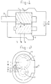
- the compressor which is conventional per se, comprises a screw 1 with a driving shaft 2.
- a screw 3 is in engagement with said screw 1 and in operation is carried by the screw 1. There is no mechanical coupling between the two screws or rotors.
- the screws 1 and 3 are supported in and enclosed by a stator housing 4.
- the gas to be compressed is fed in at the lefthand side of the housing 4, through a transverse feed 5 (see Fig. 2).
- the compressed gas is discharged at the righthand side of the housing 4, through an axial outlet 6.
- water is injected into the interior of the compressor. This water serves not only for cooling of the gas, but also for lubrication of the contact faces of the rotors 1 and 3.
- an injection point is located at point A.
- This injection point A is directed towards the contact face of the rotors 1 and 3.
- point A lies at a place where the pressure is equal to 2 P 3 plus or minus 0.5 bar, P being equal to the absolute final pressure at the compressor outlet.
- the two points B lie at a place where the pressure is equal to P 3 plus or minus 0.5 bar.
- the two points C lie at a place where the pressure is equal to the inlet pressure.
- the injected quantity of water per unit time must lie between 1% and 2% of the capacity of the compressor.
- approximately 50% of the total quantity of water must be injected in point A, approximately 20% in each point B, and approximately 5% in each point C.
- the temperature of the injected water is also of essential importance and must be at least 5 K lower than the temperature of the gas sucked in.
- the example taken is a compressor with an absolute pressure of 7 bar and a speed of 6,475 r.p.m.
- the shaft power is 7.38 kW/m3/min.
- the shaft power is 6.03 kW/m3/min.
Landscapes
- Engineering & Computer Science (AREA)
- Mechanical Engineering (AREA)
- General Engineering & Computer Science (AREA)
- Applications Or Details Of Rotary Compressors (AREA)
- Separation By Low-Temperature Treatments (AREA)
- Structures Of Non-Positive Displacement Pumps (AREA)
Claims (4)
- Schraubenverdichter mit zwei zueinander parallelen und aneinander angreifenden Schrauben (1, 3), von denen die eine (1) angetrieben wird, während die andere (3) mitgenommen wird, umgeben von einem Statorgehäuse (4) und versehen mit einem Einlaß (5) für das zu verdichtende Gas, sowie mit einem Auslaß (6) für das verdichtete Gas versehen sind, wobei das Statorgehäuse (4) außerdem einen Einspritzpunkt aufweist, durch den Wasser direkt in das Statorgehäuse (4) eingespritzt wird,
dadurch gekennzeichnet, daß sich der Einspritzpunkt an einer Stelle (A) in dem Statorgehäuse (4) befindet, wo der Druck 2

- Schraubenverdichter nach Anspruch 1,
dadurch gekennzeichnet, daß der erstgenannte Einspritzpunkt (A) in Richtung auf die Kontaktfläche zwischen den beiden Schrauben (1, 3) gerichtet ist und die übrigen Einspritzpunkte (B und C) in zwei Gruppen von je zwei angeordnet und schräg nach außen gerichtet sind. - Verfahren zum Betreiben eines Schraubenverdichters nach Anspruch 1, dadurch gekennzeichnet, daß die Menge des pro Zeiteinheit eingespritzen Wassers 1 % bis 2 % der Kapazität des Verdichters beträgt und die Temperatur des eingespritzten Wassers wenigsten 5 K niedriger als die Temperatur des Gases am Einlaß (5) des Verdichters ist.
- Verfahren nach Anspruch 3,
dadurch gekennzeichnet, daß die Menge des eingespritzen Wassers an dem erstgenannten Einspritzpunkt (A) ca. 50 % der Gesamtmenge des eingespritzten Wassers beträgt, an jedem des Satzes der bei
Applications Claiming Priority (2)
| Application Number | Priority Date | Filing Date | Title |
|---|---|---|---|
| NL8900694 | 1989-03-21 | ||
| NL8900694A NL8900694A (nl) | 1989-03-21 | 1989-03-21 | Schroefcompressor en werkwijze voor het bedrijven daarvan. |
Publications (2)
| Publication Number | Publication Date |
|---|---|
| EP0389036A1 EP0389036A1 (de) | 1990-09-26 |
| EP0389036B1 true EP0389036B1 (de) | 1993-07-28 |
Family
ID=19854333
Family Applications (1)
| Application Number | Title | Priority Date | Filing Date |
|---|---|---|---|
| EP90200581A Expired - Lifetime EP0389036B1 (de) | 1989-03-21 | 1990-03-09 | Schraubenverdichter und sein Betriebsverfahren |
Country Status (6)
| Country | Link |
|---|---|
| EP (1) | EP0389036B1 (de) |
| AT (1) | ATE92158T1 (de) |
| DE (1) | DE69002358T2 (de) |
| DK (1) | DK0389036T3 (de) |
| ES (1) | ES2043243T3 (de) |
| NL (1) | NL8900694A (de) |
Cited By (2)
| Publication number | Priority date | Publication date | Assignee | Title |
|---|---|---|---|---|
| WO2018023177A1 (en) | 2016-08-01 | 2018-02-08 | Atlas Copco Airpower, Naamloze Vennootschap | Liquid-injected compressor or expander element and method for controlling the liquid injection of a compressor or expander device |
| EP3467315A1 (de) | 2017-10-04 | 2019-04-10 | Ingersoll-Rand Company | Schraubenverdichter mit öleinspritzung in mehreren volumenverhältnissen |
Families Citing this family (10)
| Publication number | Priority date | Publication date | Assignee | Title |
|---|---|---|---|---|
| GB9211405D0 (en) | 1992-05-29 | 1992-07-15 | Nat Power Plc | A compressor for supplying compressed gas |
| AU675792B2 (en) * | 1992-05-29 | 1997-02-20 | Innogy Plc | A gas compressor |
| GB2300673B (en) * | 1992-05-29 | 1997-01-15 | Nat Power Plc | A gas turbine plant |
| DE4447097A1 (de) * | 1994-12-29 | 1996-07-04 | Guenter Kirsten | Verdichteranlage |
| DE19543879C2 (de) * | 1995-11-24 | 2002-02-28 | Guenter Kirsten | Schraubenverdichter mit Flüssigkeitseinspritzung |
| JPH11270484A (ja) * | 1998-03-24 | 1999-10-05 | Taiko Kikai Industries Co Ltd | スクリューロータ型ウエット真空ポンプ |
| JP3831110B2 (ja) | 1998-03-25 | 2006-10-11 | 大晃機械工業株式会社 | 真空ポンプのスクリューロータ |
| CN106979160A (zh) * | 2017-04-26 | 2017-07-25 | 珠海格力电器股份有限公司 | 螺杆压缩机、空调装置及制冷装置 |
| JP6899288B2 (ja) * | 2017-09-04 | 2021-07-07 | 株式会社日立産機システム | スクリュー圧縮機 |
| DE202018000178U1 (de) * | 2018-01-12 | 2019-04-15 | Leybold Gmbh | Kompressor |
Family Cites Families (5)
| Publication number | Priority date | Publication date | Assignee | Title |
|---|---|---|---|---|
| US3535057A (en) * | 1968-09-06 | 1970-10-20 | Esper Kodra | Screw compressor |
| GB1413426A (en) * | 1973-04-09 | 1975-11-12 | Zimmern B | Rotary air compressor sets with injection of water |
| DE2801408A1 (de) * | 1978-01-13 | 1979-07-19 | Linde Ag | Verfahren und vorrichtung zum kuehlen eines in einem kaeltekreislauf angeordneten verdichters der drehkolbenbauart |
| DE2853264A1 (de) * | 1978-12-09 | 1980-06-19 | Rietschle Masch App | Verfahren und einrichtung zur einspritzkuehlung von vakuumpumpen |
| FR2603666B1 (fr) * | 1986-09-10 | 1990-11-09 | Zimmern Bernard | Compresseur injecte a commutateur de liquide |
-
1989
- 1989-03-21 NL NL8900694A patent/NL8900694A/nl not_active Application Discontinuation
-
1990
- 1990-03-09 ES ES90200581T patent/ES2043243T3/es not_active Expired - Lifetime
- 1990-03-09 DE DE90200581T patent/DE69002358T2/de not_active Expired - Fee Related
- 1990-03-09 DK DK90200581.8T patent/DK0389036T3/da active
- 1990-03-09 AT AT90200581T patent/ATE92158T1/de not_active IP Right Cessation
- 1990-03-09 EP EP90200581A patent/EP0389036B1/de not_active Expired - Lifetime
Cited By (2)
| Publication number | Priority date | Publication date | Assignee | Title |
|---|---|---|---|---|
| WO2018023177A1 (en) | 2016-08-01 | 2018-02-08 | Atlas Copco Airpower, Naamloze Vennootschap | Liquid-injected compressor or expander element and method for controlling the liquid injection of a compressor or expander device |
| EP3467315A1 (de) | 2017-10-04 | 2019-04-10 | Ingersoll-Rand Company | Schraubenverdichter mit öleinspritzung in mehreren volumenverhältnissen |
Also Published As
| Publication number | Publication date |
|---|---|
| DE69002358T2 (de) | 1994-02-10 |
| NL8900694A (nl) | 1990-10-16 |
| DK0389036T3 (da) | 1993-09-27 |
| DE69002358D1 (de) | 1993-09-02 |
| ATE92158T1 (de) | 1993-08-15 |
| ES2043243T3 (es) | 1993-12-16 |
| EP0389036A1 (de) | 1990-09-26 |
Similar Documents
| Publication | Publication Date | Title |
|---|---|---|
| EP0389036A1 (de) | Schraubenverdichter und sein Betriebsverfahren | |
| EP1319132B1 (de) | Mehrstufiger hochdruckkreiselverdichter | |
| US3859815A (en) | Two-stage compression apparatus | |
| US4797068A (en) | Vacuum evacuation system | |
| US5226294A (en) | Compressor arrangement suitable for transport refrigeration systems | |
| MY119733A (en) | Rotary compressor | |
| US3184155A (en) | Motor compressor unit | |
| KR940021904A (ko) | 연소기 터어빈과 다단식 기어압축기의 조합장치에서 압축가스 흐름을 공급하기 위한 장치 및 방법 | |
| US20020044876A1 (en) | Screw compressor | |
| JPH11294362A (ja) | スクリュー圧縮機 | |
| EP0347706B1 (de) | Mehrstufiges Vakuumpumpenaggregat | |
| GB1570150A (en) | Process and apparatus for supplying compressed gas | |
| US7059837B2 (en) | Variable speed oil-injected screw compressors | |
| EP0105315B1 (de) | Verdichter des hermetischen typs | |
| EP0992747A3 (de) | Klimaanlagen | |
| SE500488C2 (sv) | Skruvkompressor med tätningsorgan | |
| US5846066A (en) | Vacuum pumps with claw-type rotor and roots-type rotor near the outlet | |
| RU2062362C1 (ru) | Многоступенчатый центробежный компрессор | |
| CS207321B2 (en) | Compressor set | |
| SU1110935A1 (ru) | Ротационный компрессор | |
| EP1174621B1 (de) | Schraubenverdichter | |
| GB832386A (en) | Improvements in rotary displacement machines | |
| US3093300A (en) | Axial flow compressor | |
| ATE142553T1 (de) | Misch- und druckluftfördergerät | |
| SU883558A1 (ru) | Ротор винтовой компрессорной машины |
Legal Events
| Date | Code | Title | Description |
|---|---|---|---|
| PUAI | Public reference made under article 153(3) epc to a published international application that has entered the european phase |
Free format text: ORIGINAL CODE: 0009012 |
|
| AK | Designated contracting states |
Kind code of ref document: A1 Designated state(s): AT BE CH DE DK ES FR GB GR IT LI LU NL SE |
|
| 17P | Request for examination filed |
Effective date: 19900726 |
|
| 17Q | First examination report despatched |
Effective date: 19920427 |
|
| GRAA | (expected) grant |
Free format text: ORIGINAL CODE: 0009210 |
|
| AK | Designated contracting states |
Kind code of ref document: B1 Designated state(s): AT BE CH DE DK ES FR GB GR IT LI LU NL SE |
|
| REF | Corresponds to: |
Ref document number: 92158 Country of ref document: AT Date of ref document: 19930815 Kind code of ref document: T |
|
| ITF | It: translation for a ep patent filed | ||
| REF | Corresponds to: |
Ref document number: 69002358 Country of ref document: DE Date of ref document: 19930902 |
|
| ET | Fr: translation filed | ||
| REG | Reference to a national code |
Ref country code: DK Ref legal event code: T3 |
|
| REG | Reference to a national code |
Ref country code: GR Ref legal event code: FG4A Free format text: 3008880 |
|
| REG | Reference to a national code |
Ref country code: ES Ref legal event code: FG2A Ref document number: 2043243 Country of ref document: ES Kind code of ref document: T3 |
|
| EPTA | Lu: last paid annual fee | ||
| PLBE | No opposition filed within time limit |
Free format text: ORIGINAL CODE: 0009261 |
|
| STAA | Information on the status of an ep patent application or granted ep patent |
Free format text: STATUS: NO OPPOSITION FILED WITHIN TIME LIMIT |
|
| 26N | No opposition filed | ||
| EAL | Se: european patent in force in sweden |
Ref document number: 90200581.8 |
|
| REG | Reference to a national code |
Ref country code: GB Ref legal event code: IF02 |
|
| PGFP | Annual fee paid to national office [announced via postgrant information from national office to epo] |
Ref country code: GR Payment date: 20030124 Year of fee payment: 14 |
|
| PGFP | Annual fee paid to national office [announced via postgrant information from national office to epo] |
Ref country code: NL Payment date: 20030131 Year of fee payment: 14 |
|
| PGFP | Annual fee paid to national office [announced via postgrant information from national office to epo] |
Ref country code: GB Payment date: 20030224 Year of fee payment: 14 |
|
| PGFP | Annual fee paid to national office [announced via postgrant information from national office to epo] |
Ref country code: FR Payment date: 20030320 Year of fee payment: 14 |
|
| PGFP | Annual fee paid to national office [announced via postgrant information from national office to epo] |
Ref country code: DK Payment date: 20030321 Year of fee payment: 14 Ref country code: BE Payment date: 20030321 Year of fee payment: 14 Ref country code: AT Payment date: 20030321 Year of fee payment: 14 |
|
| PGFP | Annual fee paid to national office [announced via postgrant information from national office to epo] |
Ref country code: SE Payment date: 20030325 Year of fee payment: 14 |
|
| PGFP | Annual fee paid to national office [announced via postgrant information from national office to epo] |
Ref country code: DE Payment date: 20030403 Year of fee payment: 14 Ref country code: CH Payment date: 20030403 Year of fee payment: 14 |
|
| PGFP | Annual fee paid to national office [announced via postgrant information from national office to epo] |
Ref country code: ES Payment date: 20030429 Year of fee payment: 14 |
|
| PGFP | Annual fee paid to national office [announced via postgrant information from national office to epo] |
Ref country code: LU Payment date: 20030512 Year of fee payment: 14 |
|
| PG25 | Lapsed in a contracting state [announced via postgrant information from national office to epo] |
Ref country code: LU Free format text: LAPSE BECAUSE OF NON-PAYMENT OF DUE FEES Effective date: 20040309 Ref country code: GB Free format text: LAPSE BECAUSE OF NON-PAYMENT OF DUE FEES Effective date: 20040309 Ref country code: AT Free format text: LAPSE BECAUSE OF NON-PAYMENT OF DUE FEES Effective date: 20040309 |
|
| PG25 | Lapsed in a contracting state [announced via postgrant information from national office to epo] |
Ref country code: SE Free format text: LAPSE BECAUSE OF NON-PAYMENT OF DUE FEES Effective date: 20040310 Ref country code: ES Free format text: LAPSE BECAUSE OF NON-PAYMENT OF DUE FEES Effective date: 20040310 |
|
| PG25 | Lapsed in a contracting state [announced via postgrant information from national office to epo] |
Ref country code: LI Free format text: LAPSE BECAUSE OF NON-PAYMENT OF DUE FEES Effective date: 20040331 Ref country code: DK Free format text: LAPSE BECAUSE OF NON-PAYMENT OF DUE FEES Effective date: 20040331 Ref country code: CH Free format text: LAPSE BECAUSE OF NON-PAYMENT OF DUE FEES Effective date: 20040331 Ref country code: BE Free format text: LAPSE BECAUSE OF NON-PAYMENT OF DUE FEES Effective date: 20040331 |
|
| BERE | Be: lapsed |
Owner name: *GRASS-AIR HOLDING B.V. Effective date: 20040331 |
|
| PG25 | Lapsed in a contracting state [announced via postgrant information from national office to epo] |
Ref country code: NL Free format text: LAPSE BECAUSE OF NON-PAYMENT OF DUE FEES Effective date: 20041001 Ref country code: DE Free format text: LAPSE BECAUSE OF NON-PAYMENT OF DUE FEES Effective date: 20041001 |
|
| PG25 | Lapsed in a contracting state [announced via postgrant information from national office to epo] |
Ref country code: GR Free format text: LAPSE BECAUSE OF NON-PAYMENT OF DUE FEES Effective date: 20041006 |
|
| GBPC | Gb: european patent ceased through non-payment of renewal fee | ||
| EUG | Se: european patent has lapsed | ||
| REG | Reference to a national code |
Ref country code: CH Ref legal event code: PL |
|
| PG25 | Lapsed in a contracting state [announced via postgrant information from national office to epo] |
Ref country code: FR Free format text: LAPSE BECAUSE OF NON-PAYMENT OF DUE FEES Effective date: 20041130 |
|
| NLV4 | Nl: lapsed or anulled due to non-payment of the annual fee |
Effective date: 20041001 |
|
| REG | Reference to a national code |
Ref country code: FR Ref legal event code: ST |
|
| PG25 | Lapsed in a contracting state [announced via postgrant information from national office to epo] |
Ref country code: IT Free format text: LAPSE BECAUSE OF NON-PAYMENT OF DUE FEES;WARNING: LAPSES OF ITALIAN PATENTS WITH EFFECTIVE DATE BEFORE 2007 MAY HAVE OCCURRED AT ANY TIME BEFORE 2007. THE CORRECT EFFECTIVE DATE MAY BE DIFFERENT FROM THE ONE RECORDED. Effective date: 20050309 |
|
| REG | Reference to a national code |
Ref country code: ES Ref legal event code: FD2A Effective date: 20040310 |