EP0389403A2 - Ecran visuel monté sur un casque avec deux oculaires interchangeables - Google Patents
Ecran visuel monté sur un casque avec deux oculaires interchangeables Download PDFInfo
- Publication number
- EP0389403A2 EP0389403A2 EP90630045A EP90630045A EP0389403A2 EP 0389403 A2 EP0389403 A2 EP 0389403A2 EP 90630045 A EP90630045 A EP 90630045A EP 90630045 A EP90630045 A EP 90630045A EP 0389403 A2 EP0389403 A2 EP 0389403A2
- Authority
- EP
- European Patent Office
- Prior art keywords
- lens
- air
- optical components
- eyepiece
- observer
- Prior art date
- Legal status (The legal status is an assumption and is not a legal conclusion. Google has not performed a legal analysis and makes no representation as to the accuracy of the status listed.)
- Withdrawn
Links
Images


Classifications
-
- G—PHYSICS
- G02—OPTICS
- G02B—OPTICAL ELEMENTS, SYSTEMS OR APPARATUS
- G02B27/00—Optical systems or apparatus not provided for by any of the groups G02B1/00 - G02B26/00, G02B30/00
- G02B27/01—Head-up displays
- G02B27/017—Head mounted
- G02B27/0176—Head mounted characterised by mechanical features
-
- A—HUMAN NECESSITIES
- A42—HEADWEAR
- A42B—HATS; HEAD COVERINGS
- A42B3/00—Helmets; Helmet covers ; Other protective head coverings
- A42B3/04—Parts, details or accessories of helmets
- A42B3/0406—Accessories for helmets
- A42B3/042—Optical devices
-
- G—PHYSICS
- G02—OPTICS
- G02B—OPTICAL ELEMENTS, SYSTEMS OR APPARATUS
- G02B27/00—Optical systems or apparatus not provided for by any of the groups G02B1/00 - G02B26/00, G02B30/00
- G02B27/01—Head-up displays
- G02B27/0101—Head-up displays characterised by optical features
-
- G—PHYSICS
- G02—OPTICS
- G02B—OPTICAL ELEMENTS, SYSTEMS OR APPARATUS
- G02B27/00—Optical systems or apparatus not provided for by any of the groups G02B1/00 - G02B26/00, G02B30/00
- G02B27/01—Head-up displays
- G02B27/0149—Head-up displays characterised by mechanical features
-
- G—PHYSICS
- G02—OPTICS
- G02B—OPTICAL ELEMENTS, SYSTEMS OR APPARATUS
- G02B27/00—Optical systems or apparatus not provided for by any of the groups G02B1/00 - G02B26/00, G02B30/00
- G02B27/01—Head-up displays
- G02B27/017—Head mounted
- G02B27/0172—Head mounted characterised by optical features
-
- G—PHYSICS
- G02—OPTICS
- G02B—OPTICAL ELEMENTS, SYSTEMS OR APPARATUS
- G02B7/00—Mountings, adjusting means, or light-tight connections, for optical elements
- G02B7/02—Mountings, adjusting means, or light-tight connections, for optical elements for lenses
- G02B7/12—Adjusting pupillary distance of binocular pairs
-
- G—PHYSICS
- G02—OPTICS
- G02B—OPTICAL ELEMENTS, SYSTEMS OR APPARATUS
- G02B27/00—Optical systems or apparatus not provided for by any of the groups G02B1/00 - G02B26/00, G02B30/00
- G02B27/01—Head-up displays
- G02B27/0101—Head-up displays characterised by optical features
- G02B2027/0118—Head-up displays characterised by optical features comprising devices for improving the contrast of the display / brillance control visibility
-
- G—PHYSICS
- G02—OPTICS
- G02B—OPTICAL ELEMENTS, SYSTEMS OR APPARATUS
- G02B27/00—Optical systems or apparatus not provided for by any of the groups G02B1/00 - G02B26/00, G02B30/00
- G02B27/01—Head-up displays
- G02B27/0101—Head-up displays characterised by optical features
- G02B2027/0138—Head-up displays characterised by optical features comprising image capture systems, e.g. camera
-
- G—PHYSICS
- G02—OPTICS
- G02B—OPTICAL ELEMENTS, SYSTEMS OR APPARATUS
- G02B27/00—Optical systems or apparatus not provided for by any of the groups G02B1/00 - G02B26/00, G02B30/00
- G02B27/01—Head-up displays
- G02B27/0149—Head-up displays characterised by mechanical features
- G02B2027/0154—Head-up displays characterised by mechanical features with movable elements
- G02B2027/0156—Head-up displays characterised by mechanical features with movable elements with optionally usable elements
-
- G—PHYSICS
- G02—OPTICS
- G02B—OPTICAL ELEMENTS, SYSTEMS OR APPARATUS
- G02B27/00—Optical systems or apparatus not provided for by any of the groups G02B1/00 - G02B26/00, G02B30/00
- G02B27/01—Head-up displays
- G02B27/0179—Display position adjusting means not related to the information to be displayed
- G02B2027/0187—Display position adjusting means not related to the information to be displayed slaved to motion of at least a part of the body of the user, e.g. head, eye
-
- G—PHYSICS
- G02—OPTICS
- G02B—OPTICAL ELEMENTS, SYSTEMS OR APPARATUS
- G02B6/00—Light guides; Structural details of arrangements comprising light guides and other optical elements, e.g. couplings
- G02B6/04—Light guides; Structural details of arrangements comprising light guides and other optical elements, e.g. couplings formed by bundles of fibres
- G02B6/06—Light guides; Structural details of arrangements comprising light guides and other optical elements, e.g. couplings formed by bundles of fibres the relative position of the fibres being the same at both ends, e.g. for transporting images
Definitions
- This invention relates to helmet mounted displays, and more particularly to a helmet mounted display having dual interchangeable optical eyepieces.
- HMDs helmet mounted displays
- the increasing complexity of these crafts has led to an increased burden on the pilot to visually interpret flight data from a large number of sources.
- the HMD helps to alleviate this burden by providing in the pilot's forward field of view a display of information essential for the pilot's performance of such tasks as target acquisition and weapon delivery.
- the HMD allows him to spend more time piloting the craft in a head-up mode, i.e., looking out at the exterior scene and not looking down as often at the instrument panel.
- the information displayed by the HMD typically consists of symbols relating to pilotage and weapon targeting. This symbol information is fed by the onboard flight computer to a cathode ray tube (CRT) image source.
- CRT cathode ray tube
- the CRT image is then projected through a series of optical components, typically including partially reflective/ partially transmissive optical components located in front of the pilot's eyes. Viewing through the partially transparent components, sometimes referred to as a "combiner", the pilot is presented with a virtual image of the CRT image projected in his view of the external "real world" scene.
- the combiner For the relatively high brightness daytime light (as compared to nighttime light), the combiner must have high transparency (see-through) since the pilot views the external scene as well as the projected symbol information. Consequently, the display source must have high brightness (e.g., a CRT written in the stroke mode) so as to produce enough contrast in the projected symbols.
- NVGs Night Vision Goggles
- An advantage of the HMD is that the nighttime viewing function can be accomplished with the HMD optical system.
- the external scene may be sensed by, for example, image intensified television of forward looking infrared devices.
- the output of these devices is electronically processed and fed to an image projection source such as a raster mode CRT.
- the processing may also include the addition of symbol data to the sensed image of the exterior scene.
- the resulting CRT image is projected in the pilot's forward field of view through the HMD projection optical components.
- the raster mode CRT images are typically much lower in luminance than the visual symbol information produced by the stroke written CRT for the daytime situation.
- Typical stroke written luminances can be 100 times as bright as typical raster mode luminances.
- the highly transmissive, only partially reflective combiner used in a HMD designed for day usage is necessarily inefficient in transferring light from the CRT to the eye. (For some typical combiner designs, brightness transfer from the CRT to the eye can be less than ten percent). Consequently, the high see-through viewing optics commonly used in prior art HMD designs are not optimally suited for night flying conditions.
- the HMD prior art attempts to solve the luminance transfer problem by using a refractive relay system which uses only a single combiner (e.g., the IHADSS HMD from Honeywell).
- these HMDs introduce other problems, e.g., the diameters of the relay lenses tend to be large, and the eye relief (i.e., the distance from the observer's eye to the nearest HMD optical component) tends to be short. These dimensions are undesirable when attempting to design an HMD to meet the geometries imposed on the HMD by the human head.
- An object of the invention is to provide a HMD comprising an arrangement of helmet mounted image projection optical components common for both daytime and nighttime use and a pair of interchangeable eyepieces, a first eyepiece optimized for daytime light conditions, the day eyepiece having high see-through transmission and intended primarily for viewing high luminance stroke written data projected in the external daytime scene, a second eyepiece optimized for nighttime light conditions, the night eyepiece being opaque and providing for efficient transmission of the light from the image source to the eye, the night eyepiece being intended for use in viewing very low luminance images such as are provided by image intensifiers used in, for example, night vision goggles, whereby it is a simple matter of interchanging between the eyepieces depending on the ambient light conditions.
- eyepieces and common relay optics provide for control of astigmatism and chromatic and spherical aberrations
- having the overall HMD provide for reduced weight and bulk.
- apparatus for displaying an image in the forward field of view of a human eye includes an image source for generating a visual image, and an arrangement of optical components disposed along an optical axis and mounted to a helmet worn by a human, the arrangement having a first portion comprising optical components that are common to both daytime and nighttime use, the arrangement also having a pair of interchangeable eyepiece portions, a first one of the pair comprising optical components optimized for daytime light conditions, a second one of the pair comprising optical components optimized for nighttime use, each one of the pair being disposed, when mounted to the helmet, along the optical axis following the first portion of optical components to present the image to the human forward field of view.
- Fig. 1 illustrates a perspective view of an aviator piloting a modern high-performance aircraft while wearing a helmet mounted display (HMD) 10 typical of that found in the prior art.
- HMD helmet mounted display
- flight information is viewed through partially transparent optical eyepieces 11,12 located along the pilot's forward line of sight
- the flight information is provided at the image surface of one or more CRTs (not shown) to a series of optical components (not shown) that relay the image to the eyepieces 11,12.
- the CRTs and projection optics can all be helmet mounted, or some portion of the display components can be located in the cockpit.
- the HMD illustrated in Fig. 1 is solely for daytime light conditions.
- the pilot desires an intensified image of the exterior scene so as to enable him to pilot the craft to the best of his ability.
- the pilot is required to remove the entire daytime HMD and replace it with an entire HMD designed for nighttime light conditions. This changeover can be awkward and dangerous when performed during flight.
- a HMD is provided having helmet mounted projection optics that allow for both daytime and nighttime usage with a reduced amount of necessary HMD component changeover.
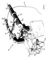
- Fig. 2 illustrates a perspective view of a preferred embodiment of a HMD 20 in accordance with the present invention.
- the HMD 20 mounts to the outer surface of a known type aviator's helmet 21, such as the model HGU55 provided by Gentex Corp. of California.
- the helmet provides an opening in the outer surface in proximity to the facial area.
- the HMD comprises two CRT image sources 22,23 together with a corresponding pair of identical optical component arrangements 24,25, one for each eye. Each CRT generates images of pilotage symbol information.
- the optical component arrangement is described in detail hereinafter with respect to the cross-sectional illustration of Fig. 3, and the optical ray diagrams of Figs. 4,5.
- Each arrangement 24,25 comprises, in part, a "relay optic" portion 24a,25a having optical components (not visible) enclosed in aluminum and used in both day and night HMD configurations.
- Each arrangement also comprises a daytime "eyepiece” portion 24b,25b having optical components optimized for daytime light conditions, and a nighttime eyepiece (not shown) 24c,25c having optical components optimized for nighttime light conditions.
- the daytime eyepieces 24b,25b mount in a first interchangeable binocular goggle assembly 28a, and the nighttime eyepieces 24c,25c mount in a second interchangeable binocular goggle assembly 28b (not shown).
- Fig 2 illustrates the HMD with the goggle assembly 28a separated from the helmet 21.
- the goggle assembly mates with each relay optic portion 24a,25a by engagement slides 29,30.
- a known type, first ball detent 31 holds the goggle assembly to a mounting block 32 on the front of the HMD.
- the ball detent 31 and engagement slides 29,30 allow the pilot to quickly remove the goggle assembly from the helmet.
- the front mounting block 32 attaches to the front of the helmet using either a fixed screw mount or a second ball detent 33.
- a first rod 34 connects the two relay optic portions together.
- the rod 34 engages a hook 35 on the crown of the helmet.
- the second ball detent 33 and rod/hook 34/35 permit the pilot to quickly disengage the entire HMD 20 from the helmet 21.
- a second rod 36 passes through the front mounting block 32 and connects to the two relay optic portions.
- the first and second rods 34,36 permit the relay optic portions to slide horizontally, thereby allowing the pilot to align the two relay optic portions for his particular eye spacing. This eye spacing is commonly referred to as the interpupillary distance (IPD).
- the second rod 36 has a knob (not shown) at one end to facilitate the IPD adjustment through a range of 58.9 - 73.3 mm, which is suitable for a wide range of pilot head sizes.
- the optical components of the eyepieces are mounted in segmented portions 39a,39b of the goggle assembly 28a.
- the segmented portions 39a,39b slide relative to one another when a retaining screw 40 is loosened.
- the pilot loosens the retaining screw 40 and adjusts the knob on the second rod 36 until the IPD is correct for his particular eye spacing. Then the pilot retightens the retaining screw.
- Fig. 3 is a cross-sectional view of either one of the optical component arrangements 24,25.
- the CRT 22 presents a visual image of flight information on a piano concave fiber optic faceplate 41 that is a part of the CRT.
- the CRT is typically a Model H-1380, one inch diameter, miniature CRT provided by Hughes Aircraft Company, Industrial Products Division, Carlsbad, California.
- the CRT drive electronics (not shown) are well known and are located in the aircraft cockpit. The drive electronics can operate the CRT in either the stroke (high brightness) mode and raster mode.
- the CRT image information is presented to the drive electronics by the on-board flight computer.
- the drive electronics connect to the CRT by a shielded electrical cable 42.
- the CRT 22 attaches to the relay optic portion 24a by means of a flange 43 secured with adhesive to the CRT and a nut assembly 44 which mates with threads 45 on the relay optic portion. This attachment point is located at an entrance aperture of the relay optic portion, as illustrated by the split line 46.
- a pair of glass optical lenses 53,54 are positioned after the CRT faceplate 41.
- the first lens 53 is positioned with a machined seat 55.
- the second lens 54 rests against the first lens.
- a first tubular spacer 56 follows the second lens, followed by a third lens 58, a second tubular spacer 59, and a second pair of lenses 61,62.
- the two lenses comprising each of the first and second lens pairs are normally positioned next to each other and are made of different types of glass or plastic material so as to reduce chromatic abberrations.
- a split line 63 designates a physical break in the relay optic portion; the segment to the left of the split line 63 is either press-fitted or secured with adhesive into the segment to the right of the split line.
- a lens retaining nut 64 is positioned inside the housing to hold the lenses 53,54,58,61,62 and spacers 56,59 in place.
- a fold mirror 66 which is used to direct (fold) the optical axis 50 downward in the relay optic portion.
- the mirror 66 is attached using conventional optical component mounting techniques known in the art so as to provide a low stress mount.
- a sixth lens 69 is positioned by a second lens retaining nut 70.
- the relay optic portion then physically terminates at a split line 72. Below the split line 72 is the daytime eyepiece 24b.
- the split line can also be considered illustrative of the location of an intermediate image focal plane 72a of the relay optic portion, and of an input aperture 72b of the eyepiece.
- a first eyepiece lens 74 Located underneath the split line 72 is a first eyepiece lens 74 positioned against a machined seat 75a with a retaining nut 75b. Also within the eyepiece is a combiner 76 and a beamsplitter 77. The beamsplitter 77 is held in place with clips 78a, 78b. The optical axis is illustrated as terminating at a focal point 79 at the observer's eye (i.e., with an observer wearing the HMD of the present invention). It is to be understood that the optical components comprising the nighttime eyepiece 25c are positioned inside the eyepiece with similar types of machined seats and retainer nuts.
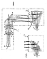
- Fig. 4 illustrates an optical ray trace of a preferred embodiment of the optical component arrangement 24,25.
- the relay optic portion components are above the split line 72, while the daytime eyepiece components are below the split line. Also, surfaces and inter-component spacings of each component are enumerated in Fig. 4. TABLE I Surface No.
- the type and radius of curvatures of the optical components is chosen in part to control astigmatism and spherical aberrations.
- the image produced by the CRT is presented on an outer surface 84 of the plano concave (CV) fiber optic faceplate 41 having a radius of curvature of 40 mm.
- the faceplate is located approximately at the entrance aperture 46 of the relay optic portion.
- the optical rays then travel through air a distance of 61.8632 mm to a first surface 85 of the first glass lens 53. All distances listed in Table I are measured from the centers of each component.
- the first surface 85 of the first lens has a convex shape and a radius of curvature of 35.488 mm.
- the lens is 3.0 mm thick and is made of F4 glass. The physical characteristics and spatial disposition of the remaining optical components are determined from Fig. 4 and Table I in a similar manner.
- surface 95 is that of the fold mirror, whose surface comprises an aluminized reflective coating.
- surface 100 is listed twice in Table I in accord with the path taken by the light which is first reflected from partially reflective surface 100 to surface 101, then reflected from partially reflective surface 101 back toward the eye, passing through the beamsplitter defined by surfaces 100 and 102.
- the first listing indicates a 34.801353 mm ray travel distance to surface 101, whereas the second listing indicates a beamsplitter thickness of 3 mm.
- surface 103 indicates the exit pupil of the optical rays. The exit pupil is approximately 8 mm in diameter.
- the relay optics are designed to produce a focused CRT image at the point in the optical path in proximity to the intermediate image focal plane 72a.
- the focused image has a magnification range of 0.5 - 4 of the image at the CRT faceplate 41.
- the focused image at the focal plane 72a is at a distance of 100 - 400 mm (i.e., the focal length of the relay optics) along the optical path 50 from the faceplate.
- the daytime eyepiece essentially creates a virtual image, in the observer's forward field of view, of the focused image at the focal plane.
- This virtual image is focused at a distance from the observer's eye of from one meter to infinity, which results in the image appearing in focus to the eye of the observer.
- the virtual image of the occupies a portion of the observer's visual field having a minimum subtense at the eye of ten (10) degrees.
- the focal length of the eyepiece is approximately 100 mm, resulting in an overall optical path length from the faceplate to the eye of 200 - 400 mm.
- the CRT faceplate is shown with 19 mm diameter which is the active image area of the miniature CRT.
- the lens diameters are chosen to contain the rays with margin to permit retention in the relay optic portions.
- the lenses comprising the relay optic portion are all glass; either F4 or fused silica (SIO2).
- the eyepiece components are all acrylic plastic. Plastic elements were chosen for weight and safety reasons. However, it is to be understood that the eyepiece lenses can be glass without detracting from the scope of the present invention.
- All components other than the folding mirror 66 have a known antireflective coating.
- the coatings on the surface 101 of the combiner 76 and the surface 100 of the beamsplitter 77 are adjusted for a reflectivity of 20%-60% (40% preferred) for visible light in the wavelength range of 400 - 700 nanometers.
- the resulting partial transmissivity of the beamsplitter and combiner allow the observer to view external scenes disposed beyond the daytime eyepiece.
- the day eyepiece can be termed to be catadioptric due to the use of partially transmissive/ partially reflective optical components.
- Each optical component in Fig. 4 can be built from the prescription data of Table I using known techniques.
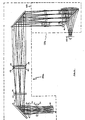
- Fig. 5 illustrates an optical ray trace of the optical components comprising the nighttime eyepiece 24c.
- Table II lists the corresponding prescription data. Since the relay optic portion components are similar as those of Fig. 4, the entries in Table II for surfaces 84-96 are similar to those in Table I.
- surface 114 of component 114a is an aluminized reflective surface which totally reflects the optical rays and blocks transmission of optical rays of the external scene disposed beyond the night eyepiece. Thus, component 114a is essentially opaque. Also, the image projected into the observer's forward field of view occupies an angle in the observer's visual field having a minimum subtense of twenty (20) degrees. TABLE II Surface No.
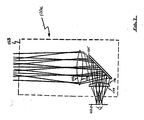
- Fig. 6 illustrates an optical ray trace of an alternative embodiment of a relay optic portion 120a and a daytime eyepiece 120b, separated at a split line 123.
- Table III list the corresponding prescription data.
- Fig. 7 illustrates the alternative embodiment nighttime eyepiece 120c.
- Table IV list the corresponding prescription data.
- the alternative embodiments are comprised entirely of conventional plastic optical elements. It should be noted that the alternative embodiments illustrated have a longer optical path length than the preferred embodiments of Figs. 4,5. This requires the CRTs 22,23 and a portion of the relay optic components to be mounted on the back side of the helmet 21 for best fit to the outer surface of the helmet. TABLE III Surface No.
- the preferred embodiment of the daytime optical components provide for data display in a 30-35 degree monocular field of view with 36% see-through luminance transmission, and approximately 6% luminance transfer from the CRT (60% beamsplitter transmission, 60% combiner transmission).
- the nighttime optical components provide for approximately 40 degree monocular field of view with no combiner see-through.
- the HMD is designed for binocular viewing using two eyepieces with 100% overlap of the left and right visual fields.
- the optics are designed to accomodate a CRT image source having an active image diameter in the range of 16 - 25 mm, with the projection optical lenses having an effective focal length in the range of 15 - 55 mm.
- the day and night optics have substantially different effective focal lengths, and the Petzval surfaces differ substantially. That is, the day and night optics ideally would have an image input surface (the CRT faceplate) of substantially different curvature. Also, simultaneous control of various aberrations is a difficult task.
- a CRT is used as the image source; however, other image sources could be used.
- a CRT was chosen because of size, weight, cost, resolution, and brightness considerations.
- the CRT is mounted on the helmet.
- the image source can be mounted off the helmet and not detract from the scope of the present invention. In this case, the image would then be presented to the helmet mounted projection optics by a flexible fiber optic cable.
- the daytime and nighttime eyepieces are comprised of plastic optical elements.
- Plastic was chosen for weight and safety reasons.
- these components can be made of a suitable light weight glass; the choice of material is not critical to the practice of the present invention.
- the eyepieces are disclosed as being housed together on sliding segments in an interchangeable goggle assembly.
- each eyepiece can be mounted individually to the corresponding relay optic portion in a suitable interchangeable structure.
- the connection in the form of the two mounting rods
- the desired binocular unit with IPD adjustment can be achieved.
- a monocular HMD may be obtained by mounting only one arrangement 24 to the helmet 21. The resulting monocular HMD arrangement is within the scope of the present invention.
- the material enclosing the relay optic portion illustrated in Fig. 3 is aluminum. However, a molded plastic or other suitable material that provides structural integrity consistent with low weight may be utilized. The choice of material itself forms no part of the present invention.
Landscapes
- Physics & Mathematics (AREA)
- General Physics & Mathematics (AREA)
- Optics & Photonics (AREA)
- Lenses (AREA)
- Helmets And Other Head Coverings (AREA)
- Devices For Indicating Variable Information By Combining Individual Elements (AREA)
Applications Claiming Priority (2)
| Application Number | Priority Date | Filing Date | Title |
|---|---|---|---|
| US313685 | 1989-02-21 | ||
| US07/313,685 US4969714A (en) | 1989-02-21 | 1989-02-21 | Helmet mounted display having dual interchangeable optical eyepieces |
Publications (2)
| Publication Number | Publication Date |
|---|---|
| EP0389403A2 true EP0389403A2 (fr) | 1990-09-26 |
| EP0389403A3 EP0389403A3 (fr) | 1991-07-17 |
Family
ID=23216696
Family Applications (1)
| Application Number | Title | Priority Date | Filing Date |
|---|---|---|---|
| EP19900630045 Withdrawn EP0389403A3 (fr) | 1989-02-21 | 1990-02-20 | Ecran visuel monté sur un casque avec deux oculaires interchangeables |
Country Status (5)
| Country | Link |
|---|---|
| US (1) | US4969714A (fr) |
| EP (1) | EP0389403A3 (fr) |
| JP (1) | JPH0339924A (fr) |
| DE (1) | DE389403T1 (fr) |
| IL (1) | IL93459A0 (fr) |
Cited By (8)
| Publication number | Priority date | Publication date | Assignee | Title |
|---|---|---|---|---|
| GB2267764A (en) * | 1992-06-10 | 1993-12-15 | Litton Systems Inc | Dual mounting assembly for night vision system |
| EP0899599A3 (fr) * | 1997-08-01 | 1999-04-14 | Colorado Microdisplay, Inc. | Système d'affichage monté sur tête |
| EP0949826A3 (fr) * | 1998-04-06 | 2000-10-25 | Optimize Incorporated | Système de visualisation binoculaire avec des plans d'image intermédiaires pour un dispositif d'affichage électronique |
| US6219186B1 (en) | 1998-04-06 | 2001-04-17 | Optimize Incorporated | Compact biocular viewing system for an electronic display |
| FR2903786A1 (fr) * | 2006-07-11 | 2008-01-18 | Thales Sa | Systeme de visualisation de casque a modules optiques interchangeables |
| CN102200641A (zh) * | 2010-03-24 | 2011-09-28 | 奥林巴斯株式会社 | 头戴式显示设备 |
| CN102445754A (zh) * | 2010-10-08 | 2012-05-09 | 精工爱普生株式会社 | 虚像显示装置 |
| FR2982376A1 (fr) * | 2011-11-07 | 2013-05-10 | Laster | Dispositif portable de vision augmentee. |
Families Citing this family (51)
| Publication number | Priority date | Publication date | Assignee | Title |
|---|---|---|---|---|
| US5982343A (en) * | 1903-11-29 | 1999-11-09 | Olympus Optical Co., Ltd. | Visual display apparatus |
| GB2246878B (en) * | 1990-07-30 | 1993-12-15 | Yazaki Corp | Variable brightness display apparatus for a vehicle |
| JPH06502054A (ja) * | 1991-04-22 | 1994-03-03 | エバンズ・アンド・サザーランド・コンピューター・コーポレーション | ビームスプリッタを用いた頭部搭載型投射ディスプレイシステム |
| US5245472A (en) * | 1991-06-26 | 1993-09-14 | Hughes Aircraft Company | High-efficiency, low-glare X-prism |
| US6097543A (en) * | 1992-02-07 | 2000-08-01 | I-O Display Systems Llc | Personal visual display |
| US5864326A (en) * | 1992-02-07 | 1999-01-26 | I-O Display Systems Llc | Depixelated visual display |
| US5303085A (en) * | 1992-02-07 | 1994-04-12 | Rallison Richard D | Optically corrected helmet mounted display |
| US5486841A (en) * | 1992-06-17 | 1996-01-23 | Sony Corporation | Glasses type display apparatus |
| JP3163786B2 (ja) | 1992-10-09 | 2001-05-08 | ソニー株式会社 | 眼鏡型映像表示装置 |
| JPH06194598A (ja) * | 1992-12-25 | 1994-07-15 | Olympus Optical Co Ltd | 頭部装着型ディスプレイ装置 |
| US5526022A (en) | 1993-01-06 | 1996-06-11 | Virtual I/O, Inc. | Sourceless orientation sensor |
| US5644324A (en) * | 1993-03-03 | 1997-07-01 | Maguire, Jr.; Francis J. | Apparatus and method for presenting successive images |
| GB9304944D0 (en) * | 1993-03-11 | 1993-04-28 | Pilkington Perkin Elmer Ltd | Head-up displays |
| JP3245478B2 (ja) * | 1993-04-27 | 2002-01-15 | オリンパス光学工業株式会社 | 頭部装着式表示装置 |
| JPH06324285A (ja) * | 1993-05-13 | 1994-11-25 | Olympus Optical Co Ltd | 視覚表示装置 |
| JPH06331928A (ja) * | 1993-05-24 | 1994-12-02 | Sony Corp | 眼鏡型ディスプレイ装置 |
| US5991087A (en) * | 1993-11-12 | 1999-11-23 | I-O Display System Llc | Non-orthogonal plate in a virtual reality or heads up display |
| JP3392929B2 (ja) * | 1994-02-07 | 2003-03-31 | オリンパス光学工業株式会社 | 映像表示装置 |
| US6160666A (en) * | 1994-02-07 | 2000-12-12 | I-O Display Systems Llc | Personal visual display system |
| USD358830S (en) | 1994-03-30 | 1995-05-30 | Litton Systems, Inc. | Helmet mount for a night vision device |
| JPH07318853A (ja) * | 1994-05-27 | 1995-12-08 | Canon Inc | 表示装置及びそれを用いた複眼式表示装置 |
| US5903395A (en) * | 1994-08-31 | 1999-05-11 | I-O Display Systems Llc | Personal visual display system |
| US5483307A (en) * | 1994-09-29 | 1996-01-09 | Texas Instruments, Inc. | Wide field of view head-mounted display |
| US5677795A (en) * | 1995-01-10 | 1997-10-14 | Hughes Aircraft Company | Modular helmet-mounted display |
| US5742264A (en) * | 1995-01-24 | 1998-04-21 | Matsushita Electric Industrial Co., Ltd. | Head-mounted display |
| US5991085A (en) | 1995-04-21 | 1999-11-23 | I-O Display Systems Llc | Head-mounted personal visual display apparatus with image generator and holder |
| US6005536A (en) * | 1996-01-16 | 1999-12-21 | National Captioning Institute | Captioning glasses |
| FR2755770B1 (fr) * | 1996-11-12 | 1999-01-22 | Sextant Avionique | Casque avec systeme de vision de nuit et optique substituable pour la vision de jour |
| US5903396A (en) * | 1997-10-17 | 1999-05-11 | I/O Display Systems, Llc | Intensified visual display |
| GB9807186D0 (en) * | 1998-04-04 | 1998-06-03 | Marconi Gec Ltd | Display arrangements |
| US6297749B1 (en) | 1998-11-06 | 2001-10-02 | Eric S. Smith | Emergency operating system for piloting an aircraft in a smoke filled cockpit |
| US6480174B1 (en) | 1999-10-09 | 2002-11-12 | Optimize Incorporated | Eyeglass-mount display having personalized fit module |
| US6292953B1 (en) * | 2000-08-17 | 2001-09-25 | Gentex Corporation | Interchangeable latch system |
| AU2002255568B8 (en) * | 2001-02-20 | 2014-01-09 | Adidas Ag | Modular personal network systems and methods |
| US7095025B2 (en) * | 2003-12-10 | 2006-08-22 | Morning Pride Manufacturing, L.L.C. | Protective shroud for thermal imaging camera mounted to protective helmet |
| US7891818B2 (en) | 2006-12-12 | 2011-02-22 | Evans & Sutherland Computer Corporation | System and method for aligning RGB light in a single modulator projector |
| KR100775744B1 (ko) * | 2007-02-07 | 2007-11-09 | 김성수 | 착탈식 안전표시구의 용이한 결합구조를 갖는 접철식안전휀스 |
| US7710569B2 (en) * | 2007-04-11 | 2010-05-04 | Remicalm, Llc | Headset mounted apparatus mounting a visor with interchangeable filter sets |
| US8358317B2 (en) | 2008-05-23 | 2013-01-22 | Evans & Sutherland Computer Corporation | System and method for displaying a planar image on a curved surface |
| US8702248B1 (en) | 2008-06-11 | 2014-04-22 | Evans & Sutherland Computer Corporation | Projection method for reducing interpixel gaps on a viewing surface |
| US8077378B1 (en) | 2008-11-12 | 2011-12-13 | Evans & Sutherland Computer Corporation | Calibration system and method for light modulation device |
| CA2777166C (fr) | 2011-05-12 | 2019-08-20 | Powerhouse Building Solutions (2009) Inc. | Systemes d'isolation et de ventilation pour les structures de batiment |
| US20120293861A1 (en) * | 2011-05-18 | 2012-11-22 | Elbit Systems Of America, Llc | System and Method for Correcting Astigmatism Caused by an Aircraft Canopy |
| WO2013000075A1 (fr) | 2011-06-29 | 2013-01-03 | Recon Instruments Inc. | Systèmes modulaires d'affichage tête haute |
| US8792176B2 (en) | 2011-08-29 | 2014-07-29 | Manufacturing Techniques, Inc. | Projection device for use with a night vision goggle system |
| US9641826B1 (en) | 2011-10-06 | 2017-05-02 | Evans & Sutherland Computer Corporation | System and method for displaying distant 3-D stereo on a dome surface |
| GB2501292A (en) * | 2012-04-19 | 2013-10-23 | Bae Systems Plc | A display |
| US9729767B2 (en) | 2013-03-22 | 2017-08-08 | Seiko Epson Corporation | Infrared video display eyewear |
| CN104750234B (zh) * | 2013-12-27 | 2018-12-21 | 中芯国际集成电路制造(北京)有限公司 | 可穿戴智能设备及可穿戴智能设备的互动方法 |
| EP3405828A1 (fr) | 2016-01-22 | 2018-11-28 | Corning Incorporated | Appareil d'affichage personnel à champ large |
| US10976551B2 (en) | 2017-08-30 | 2021-04-13 | Corning Incorporated | Wide field personal display device |
Family Cites Families (21)
| Publication number | Priority date | Publication date | Assignee | Title |
|---|---|---|---|---|
| US3059519A (en) * | 1956-09-05 | 1962-10-23 | Austin N Stanton | Headgear mounted cathode ray tube and binocular viewing device |
| US3614314A (en) * | 1967-03-21 | 1971-10-19 | Bendix Corp | Optical display means for an all-weather landing system of an aircraft |
| GB1264343A (fr) * | 1968-08-12 | 1972-02-23 | ||
| USRE27356E (en) * | 1970-08-17 | 1972-05-09 | Infinite optical image-forming apparatus | |
| US3870405A (en) * | 1973-06-12 | 1975-03-11 | Honeywell Inc | Helmet sight visors |
| US3923370A (en) * | 1974-10-15 | 1975-12-02 | Honeywell Inc | Head mounted displays |
| US4028725A (en) * | 1976-04-21 | 1977-06-07 | Grumman Aerospace Corporation | High-resolution vision system |
| GB1527049A (en) * | 1976-06-18 | 1978-10-04 | Pilkington Perkin Elmer Ltd | Head-up displays |
| FR2389911B1 (fr) * | 1977-05-03 | 1981-11-27 | Thomson Csf | |
| US4218111A (en) * | 1978-07-10 | 1980-08-19 | Hughes Aircraft Company | Holographic head-up displays |
| US4361384A (en) * | 1980-06-27 | 1982-11-30 | The United States Of America As Represented By The Secretary Of The Army | High luminance miniature display |
| JPS58500729A (ja) * | 1981-05-08 | 1983-05-06 | ル−ダ−,ニルス・イング・アルゴツト | 情報の表示装置 |
| GB2108702B (en) * | 1981-10-14 | 1985-06-19 | Marconi Avionics | Optical arrangements |
| US4763990A (en) * | 1984-02-03 | 1988-08-16 | Flight Dynamics, Inc. | Head up display system |
| US4669810A (en) * | 1984-02-03 | 1987-06-02 | Flight Dynamics, Inc. | Head up display system |
| GB2179543A (en) * | 1984-05-17 | 1987-03-11 | Secr Defence | Protective helmet equipment |
| US4660943A (en) * | 1984-12-17 | 1987-04-28 | Gec Avionics Limited | Night vision systems |
| EP0206324A3 (fr) * | 1985-06-27 | 1989-05-10 | Honeywell Inc. | Système de visualisation de deux images |
| GB8519271D0 (en) * | 1985-07-31 | 1987-10-21 | Gec Avionics | Night vision systems |
| US4761056A (en) * | 1987-03-27 | 1988-08-02 | Kaiser Aerospace And Electronics Corporation | Compact helmet mounted display |
| GB8715184D0 (en) * | 1987-06-29 | 1987-10-21 | Gec Avionics | Stereoscopic presentation of data |
-
1989
- 1989-02-21 US US07/313,685 patent/US4969714A/en not_active Expired - Fee Related
-
1990
- 1990-02-20 EP EP19900630045 patent/EP0389403A3/fr not_active Withdrawn
- 1990-02-20 DE DE199090630045T patent/DE389403T1/de active Pending
- 1990-02-20 IL IL93459A patent/IL93459A0/xx unknown
- 1990-02-21 JP JP2040848A patent/JPH0339924A/ja active Pending
Cited By (16)
| Publication number | Priority date | Publication date | Assignee | Title |
|---|---|---|---|---|
| GB2267764A (en) * | 1992-06-10 | 1993-12-15 | Litton Systems Inc | Dual mounting assembly for night vision system |
| GB2267764B (en) * | 1992-06-10 | 1995-12-13 | Litton Systems Inc | Dual mounting assembly for night vision system |
| EP0899599A3 (fr) * | 1997-08-01 | 1999-04-14 | Colorado Microdisplay, Inc. | Système d'affichage monté sur tête |
| US6034653A (en) * | 1997-08-01 | 2000-03-07 | Colorado Microdisplay, Inc. | Head-set display device |
| EP0949826A3 (fr) * | 1998-04-06 | 2000-10-25 | Optimize Incorporated | Système de visualisation binoculaire avec des plans d'image intermédiaires pour un dispositif d'affichage électronique |
| US6219186B1 (en) | 1998-04-06 | 2001-04-17 | Optimize Incorporated | Compact biocular viewing system for an electronic display |
| FR2903786A1 (fr) * | 2006-07-11 | 2008-01-18 | Thales Sa | Systeme de visualisation de casque a modules optiques interchangeables |
| EP2372431A2 (fr) | 2010-03-24 | 2011-10-05 | Olympus Corporation | Dispositif d'affichage de type facial |
| CN102200641A (zh) * | 2010-03-24 | 2011-09-28 | 奥林巴斯株式会社 | 头戴式显示设备 |
| EP2372431A3 (fr) * | 2010-03-24 | 2011-12-28 | Olympus Corporation | Dispositif d'affichage de type facial |
| US8994611B2 (en) | 2010-03-24 | 2015-03-31 | Olympus Corporation | Head-mounted type display device |
| CN102200641B (zh) * | 2010-03-24 | 2015-10-14 | 奥林巴斯株式会社 | 头戴式显示设备 |
| CN102445754A (zh) * | 2010-10-08 | 2012-05-09 | 精工爱普生株式会社 | 虚像显示装置 |
| CN102445754B (zh) * | 2010-10-08 | 2014-10-15 | 精工爱普生株式会社 | 虚像显示装置 |
| FR2982376A1 (fr) * | 2011-11-07 | 2013-05-10 | Laster | Dispositif portable de vision augmentee. |
| WO2013068688A3 (fr) * | 2011-11-07 | 2013-10-24 | Laster | Dispositif portable de vision augmentee. |
Also Published As
| Publication number | Publication date |
|---|---|
| DE389403T1 (de) | 1991-01-17 |
| JPH0339924A (ja) | 1991-02-20 |
| US4969714A (en) | 1990-11-13 |
| IL93459A0 (en) | 1990-11-29 |
| EP0389403A3 (fr) | 1991-07-17 |
Similar Documents
| Publication | Publication Date | Title |
|---|---|---|
| US4969714A (en) | Helmet mounted display having dual interchangeable optical eyepieces | |
| US4961626A (en) | Direct incorporation of night vision in a helmet mounted display | |
| US4968123A (en) | Helmet mounted display configured for simulator use | |
| US4761056A (en) | Compact helmet mounted display | |
| CA1318528C (fr) | Lunettes compactes pour voir dans l'obscurite | |
| US4755023A (en) | Headgear mounted display visor | |
| US4775217A (en) | Night vision viewing system | |
| EP0134116B1 (fr) | Système de viseur à vision de nuit | |
| EP0066402B1 (fr) | Lunette de vision nocturne | |
| US6075644A (en) | Panoramic night vision goggles | |
| EP0583116A2 (fr) | Système d'affichage | |
| US20080143639A1 (en) | Helmet-mounted display system with interchangeable optical modules | |
| US5838490A (en) | Head mounted display system using mangin mirror combiner | |
| US4993788A (en) | Head-up display systems | |
| IL149649A (en) | Compact optical architecture for wide-field helmet-mounted display | |
| US5629807A (en) | Helmet mounted image intensifier | |
| EP0065837B1 (fr) | Affichage d'information | |
| Cameron | Development of the combiner-eyepiece night-vision goggle | |
| CA2010439A1 (fr) | Afficheur monte sur un casque et dote de deux objectifs optiques interchangeables | |
| Melzer et al. | An integrated approach to helmet display system design | |
| Melzer et al. | approach has been the key driving element. An example is given of the current Agile-Eye helmet inteqrated display system, a l29field-of-view (FOV) monocular, stroke (symbols only) | |
| Raynal et al. | Advanced rotorcraft helmet display sighting system optics | |
| GB2129154A (en) | Display units | |
| Marmolejo et al. | EMU helmet mounted display | |
| Task | BASIC HMD DESIGN DECISIONS |
Legal Events
| Date | Code | Title | Description |
|---|---|---|---|
| PUAI | Public reference made under article 153(3) epc to a published international application that has entered the european phase |
Free format text: ORIGINAL CODE: 0009012 |
|
| AK | Designated contracting states |
Kind code of ref document: A2 Designated state(s): DE FR GB IT NL SE |
|
| ITCL | It: translation for ep claims filed |
Representative=s name: RICCARDI SERGIO & CO. |
|
| TCNL | Nl: translation of patent claims filed | ||
| EL | Fr: translation of claims filed | ||
| DET | De: translation of patent claims | ||
| PUAL | Search report despatched |
Free format text: ORIGINAL CODE: 0009013 |
|
| AK | Designated contracting states |
Kind code of ref document: A3 Designated state(s): DE FR GB IT NL SE |
|
| STAA | Information on the status of an ep patent application or granted ep patent |
Free format text: STATUS: THE APPLICATION IS DEEMED TO BE WITHDRAWN |
|
| 18D | Application deemed to be withdrawn |
Effective date: 19920118 |