EP0389630A1 - Verfahren zur einspritzkontrolle von elektrisch angetriebenen spritzgiessmaschinen - Google Patents
Verfahren zur einspritzkontrolle von elektrisch angetriebenen spritzgiessmaschinen Download PDFInfo
- Publication number
- EP0389630A1 EP0389630A1 EP89907830A EP89907830A EP0389630A1 EP 0389630 A1 EP0389630 A1 EP 0389630A1 EP 89907830 A EP89907830 A EP 89907830A EP 89907830 A EP89907830 A EP 89907830A EP 0389630 A1 EP0389630 A1 EP 0389630A1
- Authority
- EP
- European Patent Office
- Prior art keywords
- injection
- servomotor
- value
- error
- molding machine
- Prior art date
- Legal status (The legal status is an assumption and is not a legal conclusion. Google has not performed a legal analysis and makes no representation as to the accuracy of the status listed.)
- Granted
Links
Images


Classifications
-
- B—PERFORMING OPERATIONS; TRANSPORTING
- B29—WORKING OF PLASTICS; WORKING OF SUBSTANCES IN A PLASTIC STATE IN GENERAL
- B29C—SHAPING OR JOINING OF PLASTICS; SHAPING OF MATERIAL IN A PLASTIC STATE, NOT OTHERWISE PROVIDED FOR; AFTER-TREATMENT OF THE SHAPED PRODUCTS, e.g. REPAIRING
- B29C45/00—Injection moulding, i.e. forcing the required volume of moulding material through a nozzle into a closed mould; Apparatus therefor
- B29C45/17—Component parts, details or accessories; Auxiliary operations
- B29C45/76—Measuring, controlling or regulating
- B29C45/77—Measuring, controlling or regulating of velocity or pressure of moulding material
-
- B—PERFORMING OPERATIONS; TRANSPORTING
- B29—WORKING OF PLASTICS; WORKING OF SUBSTANCES IN A PLASTIC STATE IN GENERAL
- B29C—SHAPING OR JOINING OF PLASTICS; SHAPING OF MATERIAL IN A PLASTIC STATE, NOT OTHERWISE PROVIDED FOR; AFTER-TREATMENT OF THE SHAPED PRODUCTS, e.g. REPAIRING
- B29C45/00—Injection moulding, i.e. forcing the required volume of moulding material through a nozzle into a closed mould; Apparatus therefor
- B29C45/17—Component parts, details or accessories; Auxiliary operations
- B29C45/76—Measuring, controlling or regulating
Definitions
- the present invention relates to an injection control method in an electrically-operated injection molding machine.
- an accumulator is provided, which is connected to a hydraulic injection cylinder for supply of pressurized operating oil at a large flow rate to the same cylinder.
- an electrically-operated injection molding machine employs an injection servomotor of a type capable of producing large output with small inertia.
- an injection molding machine, equipped with an accumulator or an injection motor of the large output, small inertia type, is costly.
- the object of the present invention is to provide an injection control method in an electrically-operated injection molding machine, which is capable of sharply raising the injection speed even by the use of a low- priced electric injection molding machine.
- an injection control method which is applied to an electrically-operated injection molding machine of a type driving an injection servomotor in accordance with an error between a target value and an actual value of an injection control parameter.
- the injection control method comprises steps of: (a) preventing substantial drive of the injection servomotor at an initial stage of injection control, while the target value of the injection control parameter is increased; and (b) starting the drive of the injection servomotor when the error between the target value and the actual value of the injection control parameter reaches a predetermined value.
- the injection servomotor is capable of generating a great output torque upon start of the drive of the servomotor, even if the same servomotor is of a type other than a large output, small inertia type, because the target value of the injection control parameter associated with the drive of the injection servomotor is increased, with substantial drive of the injection servomotor kept prevented, and the drive of the injection servomotor is started when the error between the target value and the actual value of the injection control parameter reaches the predetermined value. Accordingly, the injection speed can rise rapidly even in a less costly injection molding machine, so that injection molding is carried out with a desired injection characteristic.
- the rotation rate of the injection servomotor In order to rapidly raise the injection speed in the aforementioned injection control, the rotation rate of the injection servomotor must be increased rapidly upon start of the axial movement of the injection screw. To this end, conventionally, a great output, low inertia injection servomotor is employed.
- the injection control method of the present invention contemplates to achieve this, without the need of a large output, low inertia injection servomotor.
- the invention contemplates generating a large motor output torque upon start of the axial movement of the injection screw even by the use of an ordinary servomotor.
- substantial drive of the injection servomotor i.e., substantial axial movement of the injection screw is prevented.
- a torque limit value Ts for restricting the output torque of the injection servomotor is set to a value enough to establish the equilibrium of the motor output torque and a resin pressure, i.e., a pressure of molten resin within a heating cylinder, which accommodates therein the injection screw, acting on the same screw.
- the drive of the injection servomotor is first started when a target rotational position of the injection servomotor, which has been increased while a substantial increase in an actual rotational position of the motor is kept prevented, reaches a predetermined value (a feed stop positional error Fs), i.e., when the error between the target rotational position and the actual rotational position reaches the predetermined value.
- the application of the torque limit value Ts is released when the feed stop positional error Fs is reached.
- the injection servomotor is supplied with a great drive electric current determined by the actual positional error which is increased to the value Fs.
- the injection servomotor generates a great output torque so as to axially drive the injection screw with a great driving force.
- the injection speed rises rapidly.
- the feed-stop positional error Fs is a control parameter which is associated with a conventionally known feed stop function of an injection molding machine, and the feed stop function is rendered effective from an instant at which the actual positional error exceeds the value Fs to an instant the actual positional error becomes less than the value Fs again, so as to temporally stop the distribution of the command pulses.
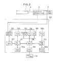
- An electrically-operated injection molding machine to which the injection control method according to an embodiment of the present invention is applied comprises various operating sections (not shown) such as injection mechanism, screw rotation mechanism, mold-clamping mechanism, eject mechanism, and is so arranged to control the drive of these operating sections by means of a numerical control unit (hereinafter, referred to as NC unit), mentioned later, and a programmable machine controller (not shown).
- the injection mechanism includes an injection servomotor 2 (Fig. 2), consisting of a D.C. servomotor, for instance, having a pulse coder 3 and operable to axially drive a screw 1 disposed within a heating cylinder 4 through a rotary motion/linear motion conversion mechanism (not shown).
- the NC unit 100 includes a central processing unit for numerical control (hereinafter, referred to as NCCPU) 101 to which connected are a ROM 101a storing therein a management program for globally controlling the injection molding machine, and a RAM 101b for temporal storage of data. Further, servo circuits for controlling the drive of servomotors of the various operating sections are connected to the NCCPU through a servo interface 107 (only the servo circuit corresponding to the injection servomotor 2 is shown by reference numeral 106).
- NCCPU central processing unit for numerical control
- ROM 101a storing therein a management program for globally controlling the injection molding machine
- RAM 101b for temporal storage of data.
- servo circuits for controlling the drive of servomotors of the various operating sections are connected to the NCCPU through a servo interface 107 (only the servo circuit corresponding to the injection servomotor 2 is shown by reference numeral 106).
- the NC unit 100 further includes a central processing unit for the programmable machine controller (hereinafter, referred to as PMCCPU) 102 to which connected are a ROM 102a storing therein, e.g., a sequence program for controlling a sequence operation of the injection molding machine, and a RAM 102b for temporal storage of data.
- PMCCPU programmable machine controller
- Reference numeral 103 denotes a non-volatile shared RAM, consisting of bubble memory, CMOS memory or the like, for storing therein an NC program and various molding condition parameters (injection speed, injection end screw position and the like); and 104 and 105, an input circuit and an output circuit, respectively.
- Respective busses of the aforesaid elements 101 - 105 are connected to a bus arbiter controller (hereinafter, referred to as BAC) 108 for control of selection of a bus to be enabled at a certain information processing cycle of the NC unit 100.
- BAC bus arbiter controller
- a manual data input device with a CRT display (hereinafter, referred to as CRT/MDI) 110 is connected to the BAC 108 through an operator panel controller 109, so that an operator is permitted to operate various operative keys of the CRT/MDI 110 including software keys and ten-key pad, so as to input various control parameters including the molding condition parameters.
- the servo circuit 106 for controlling the drive of the injection servomotor 2 comprises an error register 200 arranged to receive a command pulse train, which is distributed from the NCCPU 101 through the servo interface 107 and is indicative of a target servomotor rotational position, and a pulse train supplied from the pulse coder 3 and indicative of an actual servomotor rotational position.
- An output from the error register 200 indicative of an actual positional error is converted into a velocity command voltage by a D/A converter 201, and a frequency at which the pulses delivered from the pulse coder 3 are generated is converted into a voltage indicative of an actual rotational rate of the servomotor by means of a F/V converter 206, and further the error (velocity error) between the two voltages is amplified by an error amplifier 202 so as to obtain a torque command voltage.
- a torque limit circuit 203 receives the torque command voltage, and, on the other hand, receives, through the output circuit 105, a torque limit value delivered from the PMCCPU 102, so as to limit the torque command value up to the torque limit value.
- the error between the torque command voltage after torque restriction and a voltage which is detected by an appropriate means (not shown) and is indicative of an actual motor drive current which corresponds to an actual motor output torque, is amplified by an error amplifier 204 and a power amplifier 205, and then the thus amplified error is applied to the injection servomotor 2 for control of the motor output torque.
- the injection molding machine comprises a feed stop function for temporally stop the pulse distribution when the stored value of the error register 200, i.e., the actual positional error, exceeds a predetermined value (hereinafter, referred to as feed stop positional error) set beforehand, until the actual positional error becomes less than the feed stop positional error again.
- feed stop positional error a predetermined value
- the torque limit value Ts is set to a value which permits to achieve the equilibrium of the output torque of the injection servomotor 2 and the resin pressure at an initial stage of injection control.
- the feed stop positional error Fs is set to a value which permits the injection operation to start with the injection speed which rises sharply with operation of the servo circuit 106, when the application of the torque limit value Ts to the torque limit circuit 203 is released under a condition that the actual positional error accumulated in the error register 200 of the servo circuit 106 has reached the value of Fs.
- the value Fs is set to a value which is different from, e.g., larger than an ordinary feed stop positional error for prevention of overshoot and undershoot with respect to the target servomotor rotational position during a conventionally known acceleration/deceleration operation.
- setting of various control parameters other than the values Ts, Fs is carried out. Whereupon, the thus set control parameters are stored in predetermined address regions of the shared RAM 103, respectively, under the control of the PMCCPU 102.
- the NCCPU 101 performs the pulse distribution to servo circuits of associated operating sections of the machine through the servo interface 107, and the PMCCPU 102 performs sequence control for associated operating sections, in accordance with the NC program and various control parameters stored in the shared RAM 103 and with the sequence program stored in the ROM 102a.
- the injection molding cycle which consists of a series of processes of mold-opening, mold-closing, mold-clamping, metering, injection, hold, ejection of a molded product, etc. is carried out in basically the same manner as in the conventional molding machine.
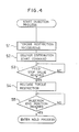
- the PMCCPU 102 executes the processing shown in Fig. 4.
- the PMCCPU 102 reads out the torque limit value Ts from the shared RAM 103 and sets the same to the torque limit circuit 203 of the servo circuit 106 through the BAC 108 and the output circuit 105 (the step Sl), and then delivers an injection start command to the NCCPU 101 through the BAC 108 and the shared RAM 103 (the step S2).
- the NCCPU 101 starts pulse distribution, which is to be executed by the NCCPU at predetermined intervals of cycle in accordance with the molding conditions stored in the shared RAM 103.
- a command pulse train is supplied from the NCCPU 101 to the error register 200 of the servo circuit 106.
- the torque limit value Ts has been already set in the aforesaid step S2, and accordingly, the output torque of the injection servo motor 2 is so controlled as to balance with the resin pressure. As a result, the substantial rotary movement of the injection servomotor 2 and the substantial axial movement of the screw 1 are prevented. In this manner, the supply of the command pulse train is continued while rotation of the injection servomotor 2 is kept stopped, and thus, pulses accumulated in the error register 200, i.e., an actual positional error increases with the elapse of time.
- the NCCPU 101 writes, at predetermined intervals of cycle, the actual positional error, which is read out from the error register 200 through the servo interface 107, into the shared RAM 103.
- the PMCCPU 102 determines whether or not the actual positional error written into the shared RAM 103 reaches the feed stop positional error Fs (the step S3).
- the PMCCPU causes the torque limit value to change from the value Fs to a value corresponding to the maximum output torque of the injection servomotor 2, for instance, to thereby release the torque restriction associated with the injection servomotor (the step S4).
- the torque limit circuit 203 permits supply of a large torque command voltage to the error amplifier 204, which is delivered from the error amplifier 202 and has a large quantity corresponding to a large actual positional error which is equal to the value Fs stored in the error register 200 at that time.
- a great drive current flows in the injection servomotor 2, so that the injection servomotor 2 having been kept unrotatable until when the torque restriction is released, is started to rotate with a great torque.
- the screw 1 is axially driven with a great drive force by means of the injection servomotor 2 through the rotary motion/linear motion conversion mechanism. In other words, the injection speed rises sharply.
- the pulse distribution for the injection servomotor 2 is temporally stopped, which is restarted when the actual positional error becomes less than the value Fs again.
- the PMCCPU 102 determines whether or not the pulse distribution up to the injection end screw position is finished, i.e., whether the screw 1 reaches its injection end position (the step S5). If so, the PMCCPU 102 completes the processing of Fig. 4. Whereupon, the conventionally known hold process is entered.
- the present invention is not limited to the aforementioned embodiment, but may be modified in various ways.
- the torque limit value Ts employed in an initial stage of the injection process is stored beforehand in the shared RAM 103
- the torque limit value Ts may be described in the sequence program.
- the present invention may be applied to an injection molding machine equipped with no feed stop function although the foregoing embodiment is applied to the injection molding machine having the feed stop function.
- a predetermined positional error corresponding to the feed stop positional error Fs is stored beforehand in the shared RAM 103.
- the feed stop function of the injection molding machine is employed for obtaining the sharply rising injection speed
- this feed stop function may be used in an ordinary manner for prevention of overshoot and undershoot in acceleration/deceleration control
- the value of Fs for embodying the method of the invention is independently set in the shared RAM 103.
- the injection molding machine is provided with an ordinary feed stop function and the function of sharply raising the injection speed according to the method of the present invention.
Landscapes
- Engineering & Computer Science (AREA)
- Manufacturing & Machinery (AREA)
- Mechanical Engineering (AREA)
- Injection Moulding Of Plastics Or The Like (AREA)
Applications Claiming Priority (2)
| Application Number | Priority Date | Filing Date | Title |
|---|---|---|---|
| JP63169085A JP2544654B2 (ja) | 1988-07-08 | 1988-07-08 | 電動式射出成形機の射出制御方式 |
| JP169085/88 | 1988-07-08 |
Publications (3)
| Publication Number | Publication Date |
|---|---|
| EP0389630A1 true EP0389630A1 (de) | 1990-10-03 |
| EP0389630A4 EP0389630A4 (en) | 1991-01-02 |
| EP0389630B1 EP0389630B1 (de) | 1993-11-03 |
Family
ID=15880047
Family Applications (1)
| Application Number | Title | Priority Date | Filing Date |
|---|---|---|---|
| EP89907830A Expired - Lifetime EP0389630B1 (de) | 1988-07-08 | 1989-06-30 | Verfahren zur einspritzkontrolle von elektrisch angetriebenen spritzgiessmaschinen |
Country Status (6)
| Country | Link |
|---|---|
| US (1) | US5034169A (de) |
| EP (1) | EP0389630B1 (de) |
| JP (1) | JP2544654B2 (de) |
| KR (1) | KR960015302B1 (de) |
| DE (1) | DE68910506T2 (de) |
| WO (1) | WO1990000468A1 (de) |
Families Citing this family (3)
| Publication number | Priority date | Publication date | Assignee | Title |
|---|---|---|---|---|
| JPH0541754U (ja) * | 1991-10-31 | 1993-06-08 | 株式会社プラ技研 | 樹脂成形押出機 |
| JP7193067B2 (ja) * | 2017-02-08 | 2022-12-20 | 国立大学法人鳥取大学 | リン吸着材及びその製造方法 |
| JP7399986B2 (ja) * | 2019-05-17 | 2023-12-18 | キヤノンバージニア, インコーポレイテッド | 製造方法および射出成形システム |
Family Cites Families (6)
| Publication number | Priority date | Publication date | Assignee | Title |
|---|---|---|---|---|
| JPS61230917A (ja) * | 1985-04-08 | 1986-10-15 | Fanuc Ltd | 射出成形機の射出圧制御方式 |
| JPS62119019A (ja) * | 1985-11-20 | 1987-05-30 | Fanuc Ltd | 射出成形機 |
| JPS62299320A (ja) * | 1986-06-19 | 1987-12-26 | Fanuc Ltd | 射出成形機の自動原点調整方式 |
| JPS6330227A (ja) * | 1986-07-24 | 1988-02-08 | Fanuc Ltd | 計量終了時におけるスクリュ−停止制御方式 |
| JPH0613185B2 (ja) * | 1986-09-10 | 1994-02-23 | 株式会社新潟鐵工所 | 電動式射出成形機における保圧力制御装置 |
| JPS6381015A (ja) * | 1986-09-25 | 1988-04-11 | Japan Steel Works Ltd:The | 電動式射出機の制御方法 |
-
1988
- 1988-07-08 JP JP63169085A patent/JP2544654B2/ja not_active Expired - Fee Related
-
1989
- 1989-06-30 KR KR1019900700482A patent/KR960015302B1/ko not_active Expired - Lifetime
- 1989-06-30 US US07/455,330 patent/US5034169A/en not_active Expired - Lifetime
- 1989-06-30 DE DE89907830T patent/DE68910506T2/de not_active Expired - Fee Related
- 1989-06-30 EP EP89907830A patent/EP0389630B1/de not_active Expired - Lifetime
- 1989-06-30 WO PCT/JP1989/000662 patent/WO1990000468A1/ja not_active Ceased
Also Published As
| Publication number | Publication date |
|---|---|
| EP0389630A4 (en) | 1991-01-02 |
| KR960015302B1 (ko) | 1996-11-07 |
| US5034169A (en) | 1991-07-23 |
| KR900701504A (ko) | 1990-12-01 |
| DE68910506T2 (de) | 1994-03-31 |
| DE68910506D1 (de) | 1993-12-09 |
| EP0389630B1 (de) | 1993-11-03 |
| JP2544654B2 (ja) | 1996-10-16 |
| WO1990000468A1 (fr) | 1990-01-25 |
| JPH0220315A (ja) | 1990-01-23 |
Similar Documents
| Publication | Publication Date | Title |
|---|---|---|
| EP0217963B1 (de) | Dosierungs- und knetsystem für einspritzgiessvorrichtungen | |
| EP0273979B1 (de) | Verfahren und vorrichtung zur gleichzeitigen numerischen steuerung von zwei achsen in einer spritzgiessmaschine | |
| KR970002297B1 (ko) | 전동식 사출성형기의 배압제어방법 및 그의 장치 | |
| JPH04232013A (ja) | プロセス変数学習機能を備えた射出成形制御装置 | |
| KR910005151B1 (ko) | 사출 성형기의 스크루우 회전 제어 방식 | |
| US4826418A (en) | Injection molding machine capable of starting and stopping by remote-control | |
| US4970447A (en) | Software servo control apparatus for use in an injection molding machine | |
| EP0276324B1 (de) | Rücksaugverfahren in einspritzgiessanlage | |
| EP0389630B1 (de) | Verfahren zur einspritzkontrolle von elektrisch angetriebenen spritzgiessmaschinen | |
| US5028365A (en) | Positioning method for an electrically-operated injection molding machine | |
| KR910005153B1 (ko) | 사출성형기의 사출축의 속도제어방식 | |
| EP0280734B2 (de) | Verfahren zum regeln des umschaltens von der verweilphase zur dosier-/mischphase beim spritzgiessen | |
| EP0233292B2 (de) | Regelungssystem für eine von servomotoren angetriebene einspritzgiessvorrichtung | |
| JPH06226787A (ja) | ノズルタッチ方法 | |
| JP3648083B2 (ja) | 射出成形機の制御方法 | |
| US20020005598A1 (en) | Method of controlling the screw of injection molding machine | |
| JP3096944B2 (ja) | 射出成形機の射出制御方法および射出成形機 | |
| JP3255728B2 (ja) | 射出成形機のフィードバック制御方法および射出成形機 | |
| JPS62117720A (ja) | 射出成形機のエジエクタ制御装置 | |
| JP2668428B2 (ja) | パージ終了検出方法 | |
| JPS6311321A (ja) | 射出成形機のエジエクト制御方法 | |
| JPH0752210A (ja) | 射出成形機の射出制御装置 | |
| JPH09174638A (ja) | 射出成形機における力のフィードバック制御方法 | |
| JPH0813485B2 (ja) | 電動式射出成形機の保圧制御方法 | |
| JPH0478089B2 (de) |
Legal Events
| Date | Code | Title | Description |
|---|---|---|---|
| PUAI | Public reference made under article 153(3) epc to a published international application that has entered the european phase |
Free format text: ORIGINAL CODE: 0009012 |
|
| 17P | Request for examination filed |
Effective date: 19900202 |
|
| AK | Designated contracting states |
Kind code of ref document: A1 Designated state(s): CH DE FR GB IT LI |
|
| A4 | Supplementary search report drawn up and despatched |
Effective date: 19901112 |
|
| AK | Designated contracting states |
Kind code of ref document: A4 Designated state(s): CH DE FR GB IT LI |
|
| 17Q | First examination report despatched |
Effective date: 19920817 |
|
| GRAA | (expected) grant |
Free format text: ORIGINAL CODE: 0009210 |
|
| AK | Designated contracting states |
Kind code of ref document: B1 Designated state(s): CH DE FR GB IT LI |
|
| PG25 | Lapsed in a contracting state [announced via postgrant information from national office to epo] |
Ref country code: IT Free format text: LAPSE BECAUSE OF FAILURE TO SUBMIT A TRANSLATION OF THE DESCRIPTION OR TO PAY THE FEE WITHIN THE PRE;WARNING: LAPSES OF ITALIAN PATENTS WITH EFFECTIVE DATE BEFORE 2007 MAY HAVE OCCURRED AT ANY TIME BEFORE 2007. THE CORRECT EFFECTIVE DATE MAY BE DIFFERENT FROM THE ONE RECORDED.SCRIBED TIME-LIMIT Effective date: 19931103 Ref country code: LI Effective date: 19931103 Ref country code: CH Effective date: 19931103 Ref country code: FR Effective date: 19931103 |
|
| REF | Corresponds to: |
Ref document number: 68910506 Country of ref document: DE Date of ref document: 19931209 |
|
| REG | Reference to a national code |
Ref country code: CH Ref legal event code: PL |
|
| EN | Fr: translation not filed | ||
| PLBE | No opposition filed within time limit |
Free format text: ORIGINAL CODE: 0009261 |
|
| STAA | Information on the status of an ep patent application or granted ep patent |
Free format text: STATUS: NO OPPOSITION FILED WITHIN TIME LIMIT |
|
| 26N | No opposition filed | ||
| PGFP | Annual fee paid to national office [announced via postgrant information from national office to epo] |
Ref country code: GB Payment date: 19980622 Year of fee payment: 10 |
|
| PG25 | Lapsed in a contracting state [announced via postgrant information from national office to epo] |
Ref country code: GB Free format text: LAPSE BECAUSE OF NON-PAYMENT OF DUE FEES Effective date: 19990630 |
|
| GBPC | Gb: european patent ceased through non-payment of renewal fee |
Effective date: 19990630 |
|
| PGFP | Annual fee paid to national office [announced via postgrant information from national office to epo] |
Ref country code: DE Payment date: 20050609 Year of fee payment: 17 |
|
| PG25 | Lapsed in a contracting state [announced via postgrant information from national office to epo] |
Ref country code: DE Free format text: LAPSE BECAUSE OF NON-PAYMENT OF DUE FEES Effective date: 20070103 |