EP0389708A2 - Verfahren und Gerät zur Geschwindigkeitssteuerung eines industrielen Roboters - Google Patents
Verfahren und Gerät zur Geschwindigkeitssteuerung eines industrielen Roboters Download PDFInfo
- Publication number
- EP0389708A2 EP0389708A2 EP89307453A EP89307453A EP0389708A2 EP 0389708 A2 EP0389708 A2 EP 0389708A2 EP 89307453 A EP89307453 A EP 89307453A EP 89307453 A EP89307453 A EP 89307453A EP 0389708 A2 EP0389708 A2 EP 0389708A2
- Authority
- EP
- European Patent Office
- Prior art keywords
- velocity
- instruction
- allowable
- control cycle
- robot
- Prior art date
- Legal status (The legal status is an assumption and is not a legal conclusion. Google has not performed a legal analysis and makes no representation as to the accuracy of the status listed.)
- Withdrawn
Links
Images


Classifications
-
- G—PHYSICS
- G05—CONTROLLING; REGULATING
- G05B—CONTROL OR REGULATING SYSTEMS IN GENERAL; FUNCTIONAL ELEMENTS OF SUCH SYSTEMS; MONITORING OR TESTING ARRANGEMENTS FOR SUCH SYSTEMS OR ELEMENTS
- G05B19/00—Program-control systems
- G05B19/02—Program-control systems electric
- G05B19/18—Numerical control [NC], i.e. automatically operating machines, in particular machine tools, e.g. in a manufacturing environment, so as to execute positioning, movement or co-ordinated operations by means of program data in numerical form
- G05B19/416—Numerical control [NC], i.e. automatically operating machines, in particular machine tools, e.g. in a manufacturing environment, so as to execute positioning, movement or co-ordinated operations by means of program data in numerical form characterised by control of velocity, acceleration or deceleration
-
- G—PHYSICS
- G05—CONTROLLING; REGULATING
- G05B—CONTROL OR REGULATING SYSTEMS IN GENERAL; FUNCTIONAL ELEMENTS OF SUCH SYSTEMS; MONITORING OR TESTING ARRANGEMENTS FOR SUCH SYSTEMS OR ELEMENTS
- G05B19/00—Program-control systems
- G05B19/02—Program-control systems electric
- G05B19/18—Numerical control [NC], i.e. automatically operating machines, in particular machine tools, e.g. in a manufacturing environment, so as to execute positioning, movement or co-ordinated operations by means of program data in numerical form
- G05B19/19—Numerical control [NC], i.e. automatically operating machines, in particular machine tools, e.g. in a manufacturing environment, so as to execute positioning, movement or co-ordinated operations by means of program data in numerical form characterised by positioning or contouring control systems, e.g. to control position from one programmed point to another or to control movement along a programmed continuous path
- G05B19/21—Numerical control [NC], i.e. automatically operating machines, in particular machine tools, e.g. in a manufacturing environment, so as to execute positioning, movement or co-ordinated operations by means of program data in numerical form characterised by positioning or contouring control systems, e.g. to control position from one programmed point to another or to control movement along a programmed continuous path using an incremental digital measuring device
- G05B19/25—Numerical control [NC], i.e. automatically operating machines, in particular machine tools, e.g. in a manufacturing environment, so as to execute positioning, movement or co-ordinated operations by means of program data in numerical form characterised by positioning or contouring control systems, e.g. to control position from one programmed point to another or to control movement along a programmed continuous path using an incremental digital measuring device for continuous-path control
- G05B19/251—Numerical control [NC], i.e. automatically operating machines, in particular machine tools, e.g. in a manufacturing environment, so as to execute positioning, movement or co-ordinated operations by means of program data in numerical form characterised by positioning or contouring control systems, e.g. to control position from one programmed point to another or to control movement along a programmed continuous path using an incremental digital measuring device for continuous-path control the positional error is used to control continuously the servomotor according to its magnitude
Definitions
- This invention relates to a method of and apparatus for controlling a velocity of an industrial robot such as a welding robot which makes a playback operation between taught points.
- FIG. 6 there is shown in a diagrammatic representation an exemplary welding process which is taken by an industrial robot such as, for example, a welding robot.
- a section between points P2 and P3 or between points P5 and P6 indicated by notched lines in Fig. 6 arc welding is performed at a velocity within an allowable velocity range which is determined in accordance with a designated welding leg length in advance.
- the robot is moved in order to move to the welding section P2 - P3 or P5 - P6, and each of the sections will be hereinafter referred as to an air cut section.
- any air cut section there is no limitation in velocity of the robot from a welding operation, and actually, the velocity of the robot here is determined in accordance with performances of motors of individual axes and so forth of the robot, that is, in accordance with the performance of the robot itself.
- the velocity of the robot is controlled in accordance with a velocity pattern as indicated by a chain line in Fig. 7. As seen from the velocity pattern, predetermined periods of time are required for an acceleration section to an instruction velocity V0 and for a deceleration section to stopping or the zero velocity.
- an allowable velocity Vmax is set in advance.
- Such allowable velocity Vmax is a maximum velocity of the robot, and in the case of a lower arm of an articulated robot, the allowable velocity Vmax is limited by a maximum velocity of rotation of a driving motor for a lower arm axis S2 and is about 80 m/min or so. Then, if the instruction velocity V0 is higher than the allowable velocity Vmax, this will lead to an error in operation of the robot. Accordingly, at a point of time at which the allowable velocity Vmax is reached during acceleration of the robot as indicated by a solid line in Fig.
- the control cycle is elongated in accordance with the instruction velocity V0 and the allowable velocity Vmax, for example, to (V0/Vmax) x (ordinary control cycle) so that the velocity of the robot may not be accelerated to the instruction velocity V0 and maintain the allowable velocity Vmax. Then, the velocity of the robot is decelerated from the allowable velocity Vmax.
- the velocity of the robot is controlled in a substantially trapezoidal velocity pattern which is obtained by cutting an upper portion of the ordinary velocity pattern shown by a chain line in Fig. 7 away along a horizontal line of the allowable velocity Vmax.
- Such velocity control is disclosed, for example, in Japanese Patent Laid-Open No. 63-80307.
- an actual velocity of the robot is sometimes different from an instruction velocity.
- a method of controlling the velocity of an industrial robot of the type which makes a playback operation between taught points and develops, after each required control cycle, a trigger signal which provides a timing for controlling the position of the robot with an aimed position provided by one of dividing points which divide a distance between the taught points into a plurality of sections, which comprises the steps of setting an allowable velocity for a first step in an acceleration section or a deceleration section for each of axes of the industrial robot, comparing, at the first step, an instruction velocity to each of the axes and the corresponding allowable velocity with each other, modifying, when the instruction velocity is higher than the allowable velocity, a control cycle after which a next trigger signal is to be developed using values of the allowable velocity and the instruction velocity, and maintaining the thus modified control cycle for the acceleration section or the deceleration section.
- a moderated acceleration/deceleration function is attained. Accordingly, there is an effect that possible production of vibrations by an edge can
- a playback operation for the first time is executed while maintaining the modified control cycle for the acceleration section or the deceleration section, and data related to a maximum velocity which is reached by such modification of the control cycle is stored in memory, whereafter in a playback operation for each of the second and following playback operations, the maximum velocity is computed in accordance with the thus stored data and the thus computed maximum velocity is used in place of the instruction velocity. Accordingly, a further moderated acceleration/deceleration function is attained, and there is an effect that possible production of vibrations by an edge can be prevented with certainty and the accuracy in control of the robot is improved significantly. Besides, a learning control function to modify a taught instruction velocity is attained for a playback operation for any of the second and following times, and there is an additional effect that an increase in acceleration/deceleration time can be prevented.
- a method of controlling the velocity of an industrial robot of the type which makes a playback operation between taught points and develops, after each required control cycle, a trigger signal which provides a timing for controlling the position of the robot with an aimed position provided by one of dividing points which divide a distance between the taught points into a plurality of sections, which comprises the steps of setting an allowable velocity for each step in an acceleration section or a deceleration section for each of axes of the industrial robot, comparing, at each step in the acceleration section or the deceleration section, an instruction velocity to each of the axes and the corresponding allowable velocity, and modifying, when the instruction velocity is higher than the allowable velocity, a control cycle after which a next trigger signal is to be developed using individual values of the allowable velocity and the instruction velocity. Accordingly, a moderated acceleration/deceleration function is attained.
- a playback operation for the first time is performed while involving modification of the control cycle, and data related to a maximum velocity which is reached by such modification of the control cycle is stored in memory, whereafter in a playback operation for each of the second and following playback operations, the maximum velocity is computed in accordance with the thus stored data and the thus computed maximum velocity is used in place of the instruction velocity. Accordingly, a further moderated acceleration/deceleration function is attained, and there is an effect that possible production of vibrations by an edge can be prevented with certainty and the accuracy in control of the robot is improved significantly.
- acceleration/deceleration time is increased a little in the playback operation for the first time because a real time processing to elongate the control cycle is executed, velocity control is executed, in each of playback operations for the second and following times, with the ordinary control cycle at an instruction velocity provided by the maximum velocity in the playback operation for the first time. Accordingly, the acceleration/deceleration time is not increased in any of the playback operations for the second and following times. Besides, a learning control function to modify a taught instruction velocity is attained for a playback operation for any of the second and following times, and there is an additional effect that an increase in acceleration/deceleration time can be prevented.
- an apparatus for controlling the velocity of an industrial robot of the type which makes a playback operation between taught points and develops, after each required control cycle, a trigger signal which provides a timing for controlling the position of the robot with an aimed position provided by one of dividing points which divide a distance between the taught points into a plurality of sections, which comprises an allowable velocity setting means for setting an allowable velocity for a first step or for each of steps in an acceleration section or a deceleration section for each of axes of the industrial robot, a comparing means for comparing, at the first step or at each of the steps, an instruction velocity to each of the axes and the corresponding allowable velocity, a control cycle computing means responsive to a result of such comparison from the comparing means for modifying, when the instruction velocity is higher than the allowable velocity, a control cycle after which a next trigger signal is to be developed using individual values of the allowable velocity and the instruction velocity, a storage means for storing therein in a playback operation for
- a moderated acceleration/deceleration function is attained, and there is an effect that possible production of vibrations by an edge can be prevented with certainty and the accuracy in control of the robot is improved significantly.
- a learning control function to modify a taught instruction velocity is attained for a playback operation for any of the second and following times, and there is an additional effect that an increase in acceleration/deceleration time can be prevented.
- an apparatus for controlling the velocity of an industrial robot of the type which interpolates a distance between taught points with a predetermined locus to make a playback operation which comprises a velocity controlling means for converting an instruction velocity of movement between the taught points into instruction velocities for individual axes of the industrial robots, comparing each of the thus converted instruction velocities for the axes with a corresponding one of allowable velocities for the axes, selecting, when the instruction velocity is higher than the allowable velocity, one of the axes at which the ratio of the instruction velocity to the corresponding allowable velocity presents a maximum value, and modifying the instruction velocity of movement between the taught points such that the instruction velocity of the one axis may be lower than the allowable velocity, a computing means for computing the thus modified instruction velocity of movement between the taught points, and a display means for displaying thereon the instruction velocity of movement thus computed by the computing means.
- FIG. 1 there is shown an apparatus for controlling the velocity of an industrial robot to which the present invention is applied.
- the apparatus here is designed as an apparatus for controlling the velocity of a two axis articulated welding robot.
- the velocity controlling apparatus shown includes an arithmetic unit 1 which develops, each time a trigger signal which will be hereinafter described is received, velocity instruction signals for motors connected to individual axes of a robot for driving articulations of the robot, that is, robot position instruction signals for one of a plurality of aimed positions between two taught points.
- the velocity controlling apparatus further includes an encoder 3 for detecting an actual velocity of each of the motors 2 (each of the axes), and a deviation counter 4 for counting a deviation of an actual velocity received from each of the encoders 3 from a corresponding instruction velocity received from the arithmetic unit 1.
- the velocity controlling apparatus further includes a digital to analog converter 5 connected to each of the deviation counters 4 and a driver 6 connected to each of the digital to analog converters 5.
- the velocity controlling apparatus further includes an allowable velocity setting device 7 for setting an allowable velocity Vmax for each axis in advance, and a comparator 8 for comparing an instruction velocity V0 from the arithmetic unit 1 and an allowable velocity Vmax from each of the allowable velocity setting devices 7 with each other and for developing a control cycle modifying signal when the instruction velocity V0 is higher than the allowable velocity Vmax but developing a control cycle maintaining signal in any other case.
- the allowable velocity varies for each step in an acceleration section or a deceleration section and is different from that in a fixed velocity section. Accordingly, a signal indicating at which step in an acceleration or deceleration section the robot is or that the robot is in a fixed velocity section is delivered from the arithmetic unit 1 to each one of the allowable velocity setting devices 7, and in response to such signals, the allowable velocity setting devices 7 deliver individual allowable velocities corresponding to the relevant section or step to the comparators 8.
- the velocity controlling apparatus further includes a control cycle computing device (velocity controlling means) 9 for delivering a trigger signal for robot position control to the arithmetic unit 1 at a required timing (control cycle).
- the control cycle computing device 9 are connected to receive a control cycle modifying signal or a control cycle maintaining signal from any of the comparators 8 and receive signals from the arithmetic unit 1 and the allowable velocity setting devices 7. If a control cycle modifying signal is received from one of the comparators 8, a time (control cycle) until a positioning instruction (trigger signal) for a next point is subsequently delivered is modified using values of an allowable velocity Vmax and an instruction velocity V0 of one of the axes at which the maximum difference between the allowable velocity Vmax and the instruction velocity V0 presents a maximum value.
- the velocity controlling apparatus further includes a velocity computing device (computing means) 10 for computing an actual velocity of the industrial robot (instruction velocity of movement between taught points).
- the velocity computing device 10 computes, when a control cycle is modified by the control cycle computing device 9, an actual velocity of the industrial robot in such a manner as will be hereinafter described in accordance with a ratio between a control cycle after such modification and another control cycle (predetermined control cycle) before such modification and also with a preset value in the industrial robot.
- the velocity controlling apparatus further includes a display section (display means) 11 provided on a teaching box or the like of the robot for displaying a result of a computation (actual velocity) by the velocity computing device 10.
- the velocity controlling apparatus additionally includes a storage section (storage means) 12 for storing therein in a playback operation for the first time data regarding a maximum velocity which is reached by modification of a control cycle by the control cycle computing device 9 (data used in the computation of the control cycle, and in the present embodiment, a ratio between an instruction velocity and an allowable velocity).
- the arithmetic unit 1 has a function as a maximum velocity computing means for computing, in a playback operation for each of the second and following times, a maximum velocity in accordance with data from the storage section 10 and for setting the value obtained by the computation in place of an instruction velocity.
- the velocity controlling apparatus of the present embodiment of the present invention has such a construction as described above and operates in the following manner.
- a velocity composite velocity of movement
- the preset velocity cannot be attained at the bottleneck of a pivot shaft S1.
- the number of instruction movement pulses (instruction velocity V0) within a next control cycle of the pivot shaft which are to be developed from the arithmetic unit 1 is equal to 10,000.
- an allowable velocity at a first step of the acceleration section (equal to 1/32 the allowable velocity of each axis upon acceleration) is set in advance in each of the allowable velocity setting devices 7.
- an allowable velocity equal to 8000/32 pulses for a first step upon acceleration is set in advance in the allowable velocity setting device 7 for the pivot shaft.
- a motor movement amount ⁇ L of each axis per control cycle computed by coordinate transformation in accordance with an instruction velocity V0 to each axis delivered from the arithmetic unit 1 is compared by a corresponding one of the comparators 8 with the corresponding allowable velocity Vmax/32 (250 pulses in the case of the example described above) set by the corresponding allowable velocity setting device 7.
- the motor movement amount ⁇ L is greater than the corresponding allowable velocity Vmax/32, the ordinary control cycle of 20 milliseconds is elongated in proportion to a ratio between them.
- a computation of the following expression ⁇ L/(Vmax/32) ⁇ ⁇ 20 (32 ⁇ ⁇ L/Vmax) ⁇ 20 (msec) is executed by the control cycle computing device 9. Accordingly, the cycle or interval of time until a next trigger signal is to be developed is elongated from 20 milliseconds to, for example, 30 milliseconds.
- the acceleration control is executed while maintaining the control cycle (for example, 30 milliseconds) computed in accordance with the expression given above. Then, after completion of the acceleration control (after lapse of 0.48 seconds of the acceleration time because 30 milliseconds is required for one step) of such 16 steps, the allowable movement velocity of 8,000 pulses for the pivot shaft corresponding to the allowable velocity Vmax for fixed velocity operation is set into the corresponding allowable velocity setting device 7, and if it is assumed that the ordinary or predetermined control cycle is equal to 20 milliseconds, then an automatic maximum velocity setting function operates in the following manner to achieve an elongation of the control cycle.
- the control cycle for example, 30 milliseconds
- the instruction movement pulses and the allowable movement pulses are compared with each other by the corresponding comparator 8.
- a control cycle modifying signal is delivered from the comparator 8 to the control cycle computing device 9.
- the control cycle computing device 9 thus elongates the control cycle in accordance with an expression of, for example, (V0/Vmax) x (predetermined control cycle) from the instruction velocity V0 (10,000 pulses) and the allowable velocity Vmax (8,000 pulses).
- control cycle is elongated to It is to be noted that where each fraction of the control cycle is equal to 2 milliseconds, the control cycle is not elongated to 25 milliseconds, but the quotient is naturally raised for the object of elongation of the control cycle, and consequently, the control cycle is elongated from 20 milliseconds to 26 milliseconds. Accordingly, the amount of movement of the pivot shaft per 20 milliseconds is equal to 10,000 x (20/26) 7, 692 pulses. Thus, a maximum velocity which is more closer to the allowable pulse number of 8,000 can be attained.
- the control cycle computing device 9 elongates the control cycle in this manner and delivers a trigger signal after a thus elongated control cycle to the arithmetic unit 1 so that the velocity control is executed at a maximum velocity which does not exceed the allowable velocity Vmax. It is to be noted that the arithmetic unit 1 delivers pulses for movement to a next point, and in response to such pulses, each of the deviation counters 4 controls the motor 2 in a direction in which the count of the deviation counter 4 is reduced to zero.
- an actual velocity of each axis of the industrial robot is computed by the velocity computing device 10 in accordance with a ratio between a predetermined control cycle and a control cycle modified by the automatic maximum velocity setting function and also to a preset velocity to the industrial robot.
- an actual velocity (velocity after correction) is computed by multiplying a ratio between the modified control cycle of 26 milliseconds and the predetermined control cycle of 20 milliseconds by the preset velocity of 150 m/min.
- an actual velocity of 150 m/min x (20/26) 115 m/min is obtained.
- the result of the computation that is, the actual velocity, is displayed on the display section 11 provided on the teaching box or the like and is notified to the operator and so forth.
- a thinned-out indication may be provided at a rate of once for each 5 control cycles, that is, once for 0. 13 seconds.
- the apparatus of the present embodiment in case there is a difference between an instruction velocity and an actual velocity (instruction velocity of movement between taught points), the actual velocity is computed by the velocity computing device 10 and displayed on the display section 11 by the automatic maximum velocity setting function (velocity controlling means). Accordingly, an operator and so on can readily recognize an actual velocity of movement of the robot.
- the velocity computing device 10 can be constructed making use of a CPU (central processing unit) for controlling the robot and a display unit existing on the teaching box can be utilized as the display section 11, there is no necessity of provision of an additional equipment in order to realize the apparatus of the present invention, and accordingly, there is no need of an additional installation cost.
- a CPU central processing unit
- the velocity computation by the velocity computing device 10 and the display of a velocity on the display section 11 in the embodiment described above may otherwise be performed only when the instruction velocity exceeds the allowable velocity so that there is the necessity of elongating the control cycle.
- the present invention is applied to a velocity controlling apparatus for an industrial robot which is provided only with an automatic maximum velocity setting function
- the present invention can be applied similarly to such a conventional velocity controlling apparatus which is provided with a moderated accelerating/decelerating function in addition to an automatic maximum velocity setting function described above.
- the method of the present invention can be applied similarly to any other multi-axis robot and also to a spherical coordinates robot, a cylindrical coordinates robot, a rectangular coordinates robot and an articulated robot.
- a motor movement amount ⁇ L of each axis (output from the computing device 1) in the control cycle immediately preceding to the deceleration section is compared by the corresponding comparator 8 with an allowable velocity Vmax for the corresponding axis set by the corresponding allowable velocity setting device 7. Since here the motor movement amount ⁇ L is greater than the allowable velocity Vmax, the ordinary control cycle of 20 milliseconds is elongated, for example, to 30 milliseconds in proportion to a ratio between them in a similar manner as in the acceleration section.
- control is executed while maintaining the control cycle of 30 milliseconds for the first step.
- a computation of comparing the allowable velocity Vmax with the motor movement amount ⁇ L to elongate the control cycle is also caused to function, and in case a control cycle obtained by the computation assumes a value which exceeds 30 milliseconds (for example, a value equal to 32 milliseconds), the value will be adopted preferentially.
- the first playback operation is executed in such a manner as described above.
- a maximum velocity (which normally corresponds to an allowable velocity Vmax) is computed by the arithmetic unit 1 in accordance with the thus stored value.
- the instruction velocity V0 is divided by the ratio (1.5).
- the arithmetic unit 1 thus delivers a thus obtained value in place of the instruction velocity V0 so that the following velocity control is executed with the normal control cycle (20 milliseconds).
- allowable velocities for the first to 16th steps of the acceleration section are set in advance into each of the allowable velocity setting devices 7.
- the allowable velocities Vmax/32, 2 ⁇ Vmax/32, ..., and Vmax are set successively beginning with the first step with ratios of the velocity units which occupy in the full 32 units like one unit for the first step, two units for the second step, and so forth.
- a motor movement amount ⁇ L of each axis for each control cycle which is found out by coordinate transformation in accordance with an instruction velocity V0 to the axis delivered from the arithmetic unit 1 is compared by the corresponding comparator 8 with an allowable velocity (Vmax/32, 2 ⁇ Vmax/32, ..., or Vmax) for the relevant step set in advance in the corresponding allowable velocity setting device 7.
- the motor movement amount ⁇ L is greater than the allowable velocity
- the normal control cycle is elongated using the motor movement amount ⁇ L related to the instruction velocity V0 and the allowable velocity for the relevant step related to the allowable velocity Vmax.
- the arithmetic unit 1 either develops a ratio with which units at a next step occupy the full units (32 units, for example) or the number of the full units and on which step a next step falls.
- the corresponding allowable velocity setting device 7 thus receives the output of the arithmetic unit 1 and either fetches a number of pulses corresponding to the relevant step from the memory or computes such number to obtain an allowable velocity (pulse number).
- control cycle computing device 9 After the control cycle computing device 9 elongates the control cycle and delivers a trigger signal and then the control for the acceleration section is completed in such a manner as described above, the ordinary automatic maximum velocity setting function is rendered effective to execute driving control with the allowable velocity Vmax.
- an appropriate maximum velocity at each deceleration step is found out from a ratio between the velocity unit number at the relevant step and the full unit number in a similar manner as in the acceleration section described above, and in case a motor movement amount computed by a coordinate computation using the value exceeds the value, the control cycle is elongated with a ratio between them by the control cycle computing device 9.
- the playback operation for the first time is executed in such a manner as described above, but since in the present embodiment an allowable velocity is set for each step, a ratio between an instruction velocity and an allowable velocity is obtained for each step.
- a certain representative value such as an average value of a plurality of ratios, a first value, an intermediate value or a last value is stored as data into the storage section 12.
- the arithmetic unit 1 finds out a maximum velocity (which normally corresponds to an allowable velocity Vmax) by dividing an instruction velocity V0 by the stored value and delivers therefrom the maximum velocity in place of the instruction value V0 and the velocity control after then is executed with the normal control cycle (20 milliseconds) in a similar manner as in the preceding embodiment described hereinabove.
- the arithmetic unit 1 is constructed such that it delivers movement pulses to a next point and the deviation counters 4 control, in response to such pulses, the motors 2 in a direction in which the counts thereof are reduced finally to zero. Then, although the delivery of a number of pulses corresponding to the instruction velocity (corresponding to the motor movement amount described above) is executed normally for each predetermined control cycle (20 milliseconds, for example), in case the pulses exceed pulses corresponding to the allowable velocity for each axis at the first step or any of the following steps in the acceleration or deceleration section, the computation of the expression given hereinabove is executed by the control cycle computing device 9 to obtain an appropriate cycle (30 milliseconds, for example) and the control cycle computing device 9 thus delivers a trigger signal after lapse of each appropriate cycle so that next instruction pulses may be developed from the arithmetic unit 1.
- the present method can be applied similarly to any other multi-axis robot and also to a spherical coordinates robot, a cylindrical coordinates robot, a rectangular coordinates robot and an articulated robot. Further, the present method can be applied similarly whether the control is PTP control, CP control or some other control.
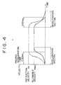
- a moderated acceleration/deceleration function can be attained by either of the first and second embodiments described hereinabove, and in case the instruction velocity V0 exceeds the allowable velocity Vmax as shown in Fig. 4, velocity control is executed without producing such an edge as is produced by the conventional method, and consequently, production of noises by such edge is prevented with certainty. Accordingly, the accuracy in control of the robot is improved significantly.
- a number of movement pulses to a next interpolation point is delivered from a main arithmetic unit 1A, and it is checked by a comparator 8A whether or not the number exceeds an allowable velocity. In case the number exceeds the allowable velocity, an appropriate control cycle is computed by a control cycle computing device 9.
- a next trigger signal to the main arithmetic unit 1A is developed at a delayed timing while a control cycle is delivered to a servo computing device 10 as data from which a train of equidistantly spaced pulses is to be produced from the control cycle computing device 9.
- the present method can be reduced to practice while pulses to be received by the deviation counters 4 are spaced by an equal time distance from each other.
- an allowable velocity set in an allowable velocity setting device 7A is not a fixed value but can be modified in response to a signal from the main arithmetic unit 1A.
Landscapes
- Engineering & Computer Science (AREA)
- Human Computer Interaction (AREA)
- Manufacturing & Machinery (AREA)
- Physics & Mathematics (AREA)
- General Physics & Mathematics (AREA)
- Automation & Control Theory (AREA)
- Numerical Control (AREA)
- Manipulator (AREA)
- Control Of Velocity Or Acceleration (AREA)
Applications Claiming Priority (2)
| Application Number | Priority Date | Filing Date | Title |
|---|---|---|---|
| JP75061/89 | 1989-03-29 | ||
| JP1075061A JPH02256483A (ja) | 1989-03-29 | 1989-03-29 | 産業用ロボットの速度制御装置 |
Publications (2)
| Publication Number | Publication Date |
|---|---|
| EP0389708A2 true EP0389708A2 (de) | 1990-10-03 |
| EP0389708A3 EP0389708A3 (de) | 1992-09-02 |
Family
ID=13565314
Family Applications (1)
| Application Number | Title | Priority Date | Filing Date |
|---|---|---|---|
| EP19890307453 Withdrawn EP0389708A3 (de) | 1989-03-29 | 1989-07-21 | Verfahren und Gerät zur Geschwindigkeitssteuerung eines industrielen Roboters |
Country Status (4)
| Country | Link |
|---|---|
| US (1) | US4972131A (de) |
| EP (1) | EP0389708A3 (de) |
| JP (1) | JPH02256483A (de) |
| KR (1) | KR910009266B1 (de) |
Cited By (3)
| Publication number | Priority date | Publication date | Assignee | Title |
|---|---|---|---|---|
| EP0530033A3 (en) * | 1991-08-30 | 1993-10-13 | Makino Milling Machine Co. Ltd. | Feed rate control method and apparatus in numerical control system |
| WO1999028798A3 (en) * | 1997-12-02 | 1999-10-14 | Lacent Technologies Inc | Gantry-mounted laser nozzle and method for controlling laser positioning |
| CN116710239A (zh) * | 2021-01-07 | 2023-09-05 | 发那科株式会社 | 机器人的动作仿真装置、机器人的控制装置以及机器人的动作仿真方法 |
Families Citing this family (19)
| Publication number | Priority date | Publication date | Assignee | Title |
|---|---|---|---|---|
| JP2643683B2 (ja) * | 1990-10-29 | 1997-08-20 | 三菱電機株式会社 | ロボットの制御方法 |
| EP0507980B1 (de) * | 1991-04-12 | 1997-07-23 | Kawasaki Jukogyo Kabushiki Kaisha | Regelungsverfahren zur Geschwindigkeitsveränderungsminimierung eines Roboters |
| JPH07200032A (ja) * | 1993-12-28 | 1995-08-04 | Nec Corp | サーボ制御装置 |
| US5740327A (en) * | 1994-12-27 | 1998-04-14 | Nec Corporation | Method of and apparatus for robot tip trajectory control |
| JP3037881B2 (ja) * | 1995-07-10 | 2000-05-08 | ファナック株式会社 | 数値制御装置 |
| DE69618606T2 (de) * | 1995-09-19 | 2002-09-12 | Kabushiki Kaisha Yaskawa Denki, Kitakyushu | Prozessor für robotersprache |
| JP4060393B2 (ja) * | 1996-01-24 | 2008-03-12 | 三菱電機株式会社 | ロボットの速度演算装置、およびロボットの速度演算方法 |
| TW369463B (en) * | 1996-03-18 | 1999-09-11 | Rorze Corp | Control device for workpiece transportation system |
| JP3453554B2 (ja) * | 2000-10-13 | 2003-10-06 | ファナック株式会社 | 加減速方法 |
| US20050107911A1 (en) * | 2003-11-14 | 2005-05-19 | Siemens Technology-To-Business Center Llc | Systems and methods for controlling load motion actuators |
| US20050107909A1 (en) * | 2003-11-14 | 2005-05-19 | Siemens Technology-To-Business Center Llc | Systems and methods for programming motion control |
| US7904182B2 (en) * | 2005-06-08 | 2011-03-08 | Brooks Automation, Inc. | Scalable motion control system |
| KR100989851B1 (ko) * | 2008-08-28 | 2010-10-29 | 세메스 주식회사 | 이송부재의 속도 조절 방법, 이를 이용한 기판 이송 방법 및 기판 처리 장치 |
| KR101749515B1 (ko) * | 2010-10-27 | 2017-06-21 | 삼성전자 주식회사 | 모터 속도 제어 장치 및 그 방법 |
| JP2014161917A (ja) * | 2013-02-21 | 2014-09-08 | Seiko Epson Corp | ロボット制御システム、ロボット、ロボット制御方法及びプログラム |
| JP6217089B2 (ja) * | 2013-02-21 | 2017-10-25 | セイコーエプソン株式会社 | ロボット制御システム、ロボット、ロボット制御方法及びプログラム |
| JP6514273B2 (ja) * | 2017-06-19 | 2019-05-15 | ファナック株式会社 | 速度を表示するロボットシステム |
| JP7311971B2 (ja) * | 2019-01-11 | 2023-07-20 | 株式会社Fuji | ロボット制御装置及びロボット制御方法 |
| JP2023146591A (ja) * | 2022-03-29 | 2023-10-12 | 株式会社デンソーウェーブ | 産業用ロボットの速度表示システム |
Family Cites Families (5)
| Publication number | Priority date | Publication date | Assignee | Title |
|---|---|---|---|---|
| US3952238A (en) * | 1973-11-29 | 1976-04-20 | Hymie Cutler | Programmable positioning apparatus and acceleration control system particularly useful therein |
| JPS55118107A (en) * | 1979-03-05 | 1980-09-10 | Hitachi Ltd | Method and device for control of automatic working device |
| JPH0799486B2 (ja) * | 1984-04-27 | 1995-10-25 | 松下電器産業株式会社 | 角加速度制御方法 |
| US4710865A (en) * | 1984-11-14 | 1987-12-01 | Canon Kabushiki Kaisha | Control system for positioning an object using switching from a speed control mode to a position control mode with adjustable brain |
| JPH01261710A (ja) * | 1988-04-13 | 1989-10-18 | Matsushita Electric Ind Co Ltd | ロボット制御装置 |
-
1989
- 1989-03-29 JP JP1075061A patent/JPH02256483A/ja active Pending
- 1989-07-14 US US07/380,118 patent/US4972131A/en not_active Expired - Lifetime
- 1989-07-21 EP EP19890307453 patent/EP0389708A3/de not_active Withdrawn
- 1989-07-31 KR KR1019890010881A patent/KR910009266B1/ko not_active Expired
Cited By (3)
| Publication number | Priority date | Publication date | Assignee | Title |
|---|---|---|---|---|
| EP0530033A3 (en) * | 1991-08-30 | 1993-10-13 | Makino Milling Machine Co. Ltd. | Feed rate control method and apparatus in numerical control system |
| WO1999028798A3 (en) * | 1997-12-02 | 1999-10-14 | Lacent Technologies Inc | Gantry-mounted laser nozzle and method for controlling laser positioning |
| CN116710239A (zh) * | 2021-01-07 | 2023-09-05 | 发那科株式会社 | 机器人的动作仿真装置、机器人的控制装置以及机器人的动作仿真方法 |
Also Published As
| Publication number | Publication date |
|---|---|
| EP0389708A3 (de) | 1992-09-02 |
| KR900014964A (ko) | 1990-10-25 |
| US4972131A (en) | 1990-11-20 |
| JPH02256483A (ja) | 1990-10-17 |
| KR910009266B1 (ko) | 1991-11-07 |
Similar Documents
| Publication | Publication Date | Title |
|---|---|---|
| US4972131A (en) | Method of an apparatus for controlling velocity of industrial robot | |
| US4815007A (en) | Apparatus for controlling a robot | |
| EP0060563B1 (de) | Steuergerät zum Interpolieren für einen industriellen, gegliederten Roboter | |
| US4348731A (en) | Automatic working apparatus and method of controlling the same | |
| US4432063A (en) | Apparatus for automatically moving a robot arm along a nonprogrammed path | |
| US4683543A (en) | Time-based interpolation control of a robot | |
| US5070287A (en) | Method for a numerical positioning control system | |
| US4685067A (en) | Control system for program controlled manipulator having multiple triggered functions between programmed points | |
| EP0240570A1 (de) | Beschleunigungs- und geschwindigkeitsabnahmesteuerungssystem für roboter mit waagerechtem gelenk | |
| JPH0430203A (ja) | ロボットの加減速時定数制御方法 | |
| US5416394A (en) | Motor control method and apparatus thereof in numerical control systems | |
| US4914363A (en) | Method for controlling the motion of a machine element | |
| JPH04235610A (ja) | 産業用ロボットの異常検出装置 | |
| EP0076331A1 (de) | Robotersteuergerät | |
| JP3202456B2 (ja) | ハンド機構の制御装置 | |
| EP0148425A2 (de) | Verfahren und Gerät zur Steuerung eines Roboters | |
| JPH1039916A (ja) | 多関節ロボットの加減速制御方法 | |
| JP2688491B2 (ja) | 産業用ロボットの速度制御方法および装置 | |
| JPH07111647B2 (ja) | ロボットアームの制御方法 | |
| JPS60220408A (ja) | 関節形ロボツト用制御装置 | |
| JPH01200414A (ja) | 産業用ロボットの速度制御方法 | |
| JPS6272007A (ja) | ロボツトの緩衝制御方法 | |
| JPH07261822A (ja) | ロボットの加減速時間決定方法および加減速制御方法 | |
| JPS6272008A (ja) | ロボツトの緩衝制御方法 | |
| JP2635106B2 (ja) | ロボットの作業領域制限装置 |
Legal Events
| Date | Code | Title | Description |
|---|---|---|---|
| PUAI | Public reference made under article 153(3) epc to a published international application that has entered the european phase |
Free format text: ORIGINAL CODE: 0009012 |
|
| 17P | Request for examination filed |
Effective date: 19890727 |
|
| AK | Designated contracting states |
Kind code of ref document: A2 Designated state(s): DE FR GB IT |
|
| PUAL | Search report despatched |
Free format text: ORIGINAL CODE: 0009013 |
|
| AK | Designated contracting states |
Kind code of ref document: A3 Designated state(s): DE FR GB IT |
|
| 17Q | First examination report despatched |
Effective date: 19930819 |
|
| STAA | Information on the status of an ep patent application or granted ep patent |
Free format text: STATUS: THE APPLICATION IS DEEMED TO BE WITHDRAWN |
|
| 18D | Application deemed to be withdrawn |
Effective date: 19931230 |