EP0389738A2 - Fonctionnement d'une tête d'impression accordé par ajustement de la viscosité de l'encre - Google Patents
Fonctionnement d'une tête d'impression accordé par ajustement de la viscosité de l'encre Download PDFInfo
- Publication number
- EP0389738A2 EP0389738A2 EP90100366A EP90100366A EP0389738A2 EP 0389738 A2 EP0389738 A2 EP 0389738A2 EP 90100366 A EP90100366 A EP 90100366A EP 90100366 A EP90100366 A EP 90100366A EP 0389738 A2 EP0389738 A2 EP 0389738A2
- Authority
- EP
- European Patent Office
- Prior art keywords
- ink
- nozzle
- meniscus
- nozzles
- viscosity
- Prior art date
- Legal status (The legal status is an assumption and is not a legal conclusion. Google has not performed a legal analysis and makes no representation as to the accuracy of the status listed.)
- Withdrawn
Links
Images
Classifications
-
- B—PERFORMING OPERATIONS; TRANSPORTING
- B41—PRINTING; LINING MACHINES; TYPEWRITERS; STAMPS
- B41J—TYPEWRITERS; SELECTIVE PRINTING MECHANISMS, i.e. MECHANISMS PRINTING OTHERWISE THAN FROM A FORME; CORRECTION OF TYPOGRAPHICAL ERRORS
- B41J2/00—Typewriters or selective printing mechanisms characterised by the printing or marking process for which they are designed
- B41J2/005—Typewriters or selective printing mechanisms characterised by the printing or marking process for which they are designed characterised by bringing liquid or particles selectively into contact with a printing material
- B41J2/01—Ink jet
- B41J2/135—Nozzles
- B41J2/14—Structure thereof only for on-demand ink jet heads
- B41J2/1433—Structure of nozzle plates
-
- B—PERFORMING OPERATIONS; TRANSPORTING
- B41—PRINTING; LINING MACHINES; TYPEWRITERS; STAMPS
- B41J—TYPEWRITERS; SELECTIVE PRINTING MECHANISMS, i.e. MECHANISMS PRINTING OTHERWISE THAN FROM A FORME; CORRECTION OF TYPOGRAPHICAL ERRORS
- B41J2/00—Typewriters or selective printing mechanisms characterised by the printing or marking process for which they are designed
- B41J2/005—Typewriters or selective printing mechanisms characterised by the printing or marking process for which they are designed characterised by bringing liquid or particles selectively into contact with a printing material
- B41J2/01—Ink jet
- B41J2/135—Nozzles
- B41J2/16—Production of nozzles
- B41J2/1606—Coating the nozzle area or the ink chamber
-
- B—PERFORMING OPERATIONS; TRANSPORTING
- B41—PRINTING; LINING MACHINES; TYPEWRITERS; STAMPS
- B41J—TYPEWRITERS; SELECTIVE PRINTING MECHANISMS, i.e. MECHANISMS PRINTING OTHERWISE THAN FROM A FORME; CORRECTION OF TYPOGRAPHICAL ERRORS
- B41J2/00—Typewriters or selective printing mechanisms characterised by the printing or marking process for which they are designed
- B41J2/005—Typewriters or selective printing mechanisms characterised by the printing or marking process for which they are designed characterised by bringing liquid or particles selectively into contact with a printing material
- B41J2/01—Ink jet
- B41J2/135—Nozzles
- B41J2/16—Production of nozzles
- B41J2/162—Manufacturing of the nozzle plates
-
- B—PERFORMING OPERATIONS; TRANSPORTING
- B41—PRINTING; LINING MACHINES; TYPEWRITERS; STAMPS
- B41J—TYPEWRITERS; SELECTIVE PRINTING MECHANISMS, i.e. MECHANISMS PRINTING OTHERWISE THAN FROM A FORME; CORRECTION OF TYPOGRAPHICAL ERRORS
- B41J2/00—Typewriters or selective printing mechanisms characterised by the printing or marking process for which they are designed
- B41J2/005—Typewriters or selective printing mechanisms characterised by the printing or marking process for which they are designed characterised by bringing liquid or particles selectively into contact with a printing material
- B41J2/01—Ink jet
- B41J2/135—Nozzles
- B41J2/16—Production of nozzles
- B41J2/1621—Manufacturing processes
- B41J2/1625—Manufacturing processes electroforming
-
- B—PERFORMING OPERATIONS; TRANSPORTING
- B41—PRINTING; LINING MACHINES; TYPEWRITERS; STAMPS
- B41J—TYPEWRITERS; SELECTIVE PRINTING MECHANISMS, i.e. MECHANISMS PRINTING OTHERWISE THAN FROM A FORME; CORRECTION OF TYPOGRAPHICAL ERRORS
- B41J2/00—Typewriters or selective printing mechanisms characterised by the printing or marking process for which they are designed
- B41J2/005—Typewriters or selective printing mechanisms characterised by the printing or marking process for which they are designed characterised by bringing liquid or particles selectively into contact with a printing material
- B41J2/01—Ink jet
- B41J2/17—Ink jet characterised by ink handling
- B41J2/195—Ink jet characterised by ink handling for monitoring ink quality
-
- B—PERFORMING OPERATIONS; TRANSPORTING
- B41—PRINTING; LINING MACHINES; TYPEWRITERS; STAMPS
- B41J—TYPEWRITERS; SELECTIVE PRINTING MECHANISMS, i.e. MECHANISMS PRINTING OTHERWISE THAN FROM A FORME; CORRECTION OF TYPOGRAPHICAL ERRORS
- B41J2/00—Typewriters or selective printing mechanisms characterised by the printing or marking process for which they are designed
- B41J2/005—Typewriters or selective printing mechanisms characterised by the printing or marking process for which they are designed characterised by bringing liquid or particles selectively into contact with a printing material
- B41J2/01—Ink jet
- B41J2/135—Nozzles
- B41J2/14—Structure thereof only for on-demand ink jet heads
- B41J2002/14475—Structure thereof only for on-demand ink jet heads characterised by nozzle shapes or number of orifices per chamber
Definitions
- This invention relates to ink-jet printers, specifically thermal ink-jet printers, and more particularly, to a structure for substantially improving the performance of the nozzle(s) in a thermal ink-jet printhead.
- This improvement in stability and consistency of operation extends the firing frequency range of the nozzle and reduces cross-talk, as well as desensitizes the exterior surfaces of the jetting nozzles to their wettability state.
- This invention is of particular value in those circumstances of design in which other means of attaining the above-mentioned operating benefits are not available through geometry changes due to manufacturing process constraints.
- any providently designed ink-jet printhead must include some features to accomplish decoupling between the nozzles and the common ink supply plenum so that the plenum does not supply a cross-talk path between neighboring nozzles.
- the motion of the meniscus present in each nozzle must be carefully controlled so as to prevent any oscillation or "ringing" of the meniscus caused by refill dynamics from interfering with the ejection of subsequently fired droplets. Ordinarily, the "settling time" required between firings sets a limit on the maximum repetition rate at which the nozzle can operate. If an ink droplet is fired from a nozzle too soon after the previous firing, the ringing of the meniscus modulates the quantity of ink in the second droplet out.
- a small and very shallow puddle of ink is typically "stranded" in the immediate vicinity of the nozzle after each firing and refill cycle.
- low frequency operating conditions typically less than about 1,500 Hz - ample time exists between firings for essentially all of this stranded ink to be wicked back up by the nozzles.
- high frequency operation typically greater than about 1,500 Hz and above - a new accumulation of puddled ink occurs at the nozzle lip.
- This accumulation can also occur at low frequencies if (1) the surface tension of the ink is sufficiently low, (2) the exterior surface of the orifice plate is sufficiently wettable, or (3) the back pressure (defined as the abso lute value of the static negative gauge pressure in the ink plenum) is sufficiently high (at least about -6 inches H2O).
- This accumulated ink has a deleterious effect upon print quality by capturing and deflecting the ejected ink droplet during the phase of droplet ejection when the tail is about to detach itself from the meniscus and follow the head of the droplet away from the nozzle.
- This direction error is integrated over the flight time of the droplet to result in a dot placement position error on the print medium. Since these errors are random in magnitude and direction, the result is an unpredictable and serious degradation of print quality. In some cases, the ink accumulation is severe enough to completely block droplet ejection from the nozzle.
- any providently designed ink jet printhead must include some features to minimize meniscus overshoot and minimize the time required for the meniscus oscillations to decay away, so that the preceding scenario (referred to as "nozzle wet-out") is avoided.
- wet-out can be caused or exacerbated by spray that breaks off the tail of the drop and rains back down on the nozzle plate. This is worst for low viscosity, high velocity drops.
- wet-out is prevented by maintaining a static negative pressure, also known as back pressure, throughout the ink supply system so as to define an equilibrium position for the meniscus which lies inside the nozzle bore.
- a static negative pressure also known as back pressure
- Another method involves the use of anti-wetting coatings applied to the area surrounding the nozzle lip, which prevent meniscus breakoff during over-shoot.
- Yet another method is to increase the amount of viscous damping present in the ink supply system, thereby holding overshoot below the value required to initiate wet-out.
- Still another method is to provide a contact-line barrier that prevents the puddle from advancing out past a certain radius.
- Anti-wetting coatings are of limited utility in preventing wet-out during overshoot since their lifetimes are typically shorter than that of the printheads to which they have been applied, causing wet-out to reappear prior to the completion of the printhead's service life. Furthermore, it is difficult to sufficiently immobilize these coatings so that wiping detritus from nozzles does not force the coating down into the bores, wreaking havoc irreversibly upon the printhead.
- Resistive decoupling uses the fluid friction present in the ink feed channels as a means of dissipating the energy content of the cross-talk surges, thereby preventing the dynamics of any single meniscus from being strong strictlyly felt by its nearest neighbors. In the prior art, this is typically implemented by making the ink feed channels longer or smaller in cross-section than the main supply plenum. While these are simple solutions, they have several drawbacks. First, such solutions rely upon fluid motion to generate the pressure drops associated with the energy dissipation; as such, they can only attenuate the cross-talk surges, not completely block them. Thus, some cross-talk "leakages" will always be present.
- the feed channels are made as long and slender as possible, thereby maximizing the inertial aspect of the fluid entrained within them.
- the inertia of the fluid "clamps" its ability to respond to cross-talk surges in proportion to the suddenness of the surge and thereby inhibits the transmission of cross-talk pulses into or out of the ink feed channel. While this decoupling scheme is used in the prior art, it requires considerable area within the print head to implement, making a compact structure impossible.
- the resistive component of a pipe having a rectangular cross-section scales directly with length and inversely with the third power of the smaller of the two cross-section dimensions, the flow resistance can grow to an unacceptable level, compromising refill speed. More importantly, however, are the dynamic effects caused by the coupling of this inertance to the compliance of the nozzle meniscus, as will be discussed below.
- the inertia of the fluid entrained within the feed channel increases.
- this inertia is coupled to the compliance of the meniscus in the nozzle, it results in a lower resonant frequency of oscillation of the meniscus, which requires a longer settling time between firings of the nozzle.
- the inertial effect and the resistive effect are tied together, with the net effect being that settling time cannot be reduced.
- Capacitive decoupling has been proven effective at droplet ejection frequencies below that corresponding to the resonant frequency of the nozzle meniscus coupled to the feed channel inertia.
- its implementation at frequencies near meniscus resonance is also complicated by interactive effects.
- the isolator orifice acts as a low impedance shunt path for high frequency surges.
- the high frequency impedance of an ink feed channel terminated at its plenum end with an isolator orifice will be lower than an equivalent channel without an isolator. This means that during the bubble growth phase, blow-back flow away from the nozzle is increased by the isolator orifice.
- the two-orifice system will thus resonate at a higher frequency, which is a benefit from a settling time point of view, but the energy stored in the resonating system still needs to be dissipated and therefore constrictive damping will be necessary in such an implementation. While the effects of these resonances is poorly understood at this time, the efficiency decrease may be severe enough to prevent the printhead from working.
- the viscosity of the jetted fluid is adjusted to control the quantity of damping present in the fluid supply channels or refill ports of the ink jet printhead. Since any viscosity increase acts to increase viscous damping present throughout the ink supply circuit, the feed channel dimensions in the supply circuit may be increased in order to prevent excessive pressure drops within the supply circuit. From a processing and manufacturing standpoint, enlargement of these features is simple, in contrast to the much more difficult problem of making the same features smaller, as would be required to enhance damping via the traditional techniques discussed above in the Background Art.
- the issue of insufficient damping at the manufacturable limit of the barrier structure is addressed.
- the channel architectures are enlarged to accommodate the thicker ink.
- the original ink had a viscosity of 1.2 cp.
- the intermediate ink viscosity was 5 cp.
- the thickest ink had a viscosity of 11 cp.
- This invention involves adjustment of ink viscosity as a means of enhancing printhead performance in situations where hydraulic tuning is impossible or impractical, i.e., head architectures which are already at the limits of manufacturability and/or which are no longer available for changes due to other design constraints. Adjustment of ink viscosity allows an otherwise impossible range of tradeoffs between nozzle refill and meniscus settling time to be made in such printheads.
- the operating speed improvements which this technique permit are quite large: a three- to five-fold increase in operating speed over current state of the art.
- This invention allows small drop-volume printers to operate without the ordinarily-encountered stability problems at droplet ejection rated above 10 kHz. It also allows the dynamics of ink droplet formation to be decoupled from the wettability of the orifice plate, which prevents uneven frequency response, trajectory errors and air ingestion. It allows these printheads to avoid such characteristics even in those situations where similar tuning efforts (via inclusion of lumped resistive elements, for instance) are prohibited.
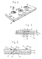
- FIG. 1 a portion of a printhead is depicted in FIG. 1.
- a nozzle plate 10 in which are recessed a plurality of nozzles 12 in individual recesses 13.
- Ink 14 is fired from resistors through the nozzles in a particular arrangement toward a print medium (e.g., paper) to form alphanumeric characters and graphics.
- a print medium e.g., paper
- FIG. 2 depicts a portion of a feed chamber 16 in which is located a resistor 18; there is one resistor associated with each nozzle 12.
- Ink is fed into the feed chambers from a plenum (not shown).
- the resistor 18 Upon receiving a pulse of energy from an external source, the resistor 18 is heated to a level sufficient to expel a droplet of ink 14 toward the print medium.
- additional ink fills the chamber 16 in preparation for another firing.
- the nozzle 12 has a nozzle diameter d; each resistor covers a square area with side dimension s; the channel width is given by w.
- the thickness of the nozzle plate 10 is t p
- the thickness of barrier layer 20 is t b .
- the printhead employs a barrier layer 20 comprising Vacrel 55 ⁇ m thick and a nozzle plate 10 comprising gold-plated nickel 63 ⁇ m thick.
- the nozzles 12 are 47 ⁇ 3 ⁇ m diameter, with resistors 64 ⁇ m x 64 ⁇ m, and channel width 84 ⁇ m wide.
- a puddle 22 of ink may form adjacent the nozzle 12. If not wicked back into the chamber, such a puddle may have a deleterious effect upon print quality by interfering with the droplet 14 of ink as it is ejected from the nozzle 12.
- the meniscus overshoots its equilibrium position, is slowed, stopped, and eventually reversed by the surface tension of the meniscus.
- the maximum overshoot occurs when the meniscus is stopped.
- ⁇ corresponds to the maximum overshoot of the meniscus.
- the angle ⁇ is defined by a tangent to the meniscus surface at the nozzle perimeter and a line drawn parallel to the top plate surface. To avoid spillage onto the top plate, ⁇ should be less than ⁇ w , the characteristic wetting angle for the ink and top plate materials.
- a stable drop generator is one that makes drops with consistent trajectories, volumes, speeds, and break-up patterns. In accordance with the invention, this stability becomes more likely as the viscosity is increased. This is because it is the damping effect of viscosity that will balance and control the inertial and surface forces that drive the refill and ejection processes. Unstable drop generators with low viscosity are characterized by chaotic meniscus movement, large meniscus overshoots, erratic spray patterns, and puddles 22.
- This stability can bo measured by looking at the accuracy and consistency of dot placement and size. Stability was measured by looking at line spacing on paper. The odd-numbered nozzles in the pen were fired across the page, forming a set of parallel lines. Then, an identical pattern was made with the even-numbered nozzles on a different part of the page. A vision system then examined the patterns, measuring line spacing uniformity and line width uniformity.
- diethylene glycol was used to increase the viscosity of the inks in the foregoing examples, it will be readily clear to those skilled in this art that the teachings of this invention are applicable to any of the water-miscible glycols typically used in ink-jet printing.
- ethylene glycol and propylene glycol are but a few examples of the many glycols that are used in ink-jet printing, and an increase in the glycol content relative to water will accomplish the same purpose, with the same end result as indicated above.
Landscapes
- Engineering & Computer Science (AREA)
- Manufacturing & Machinery (AREA)
- Quality & Reliability (AREA)
- Particle Formation And Scattering Control In Inkjet Printers (AREA)
- Inks, Pencil-Leads, Or Crayons (AREA)
- Ink Jet (AREA)
Applications Claiming Priority (2)
| Application Number | Priority Date | Filing Date | Title |
|---|---|---|---|
| US32921889A | 1989-03-27 | 1989-03-27 | |
| US329218 | 1989-03-27 |
Publications (2)
| Publication Number | Publication Date |
|---|---|
| EP0389738A2 true EP0389738A2 (fr) | 1990-10-03 |
| EP0389738A3 EP0389738A3 (fr) | 1991-01-09 |
Family
ID=23284398
Family Applications (1)
| Application Number | Title | Priority Date | Filing Date |
|---|---|---|---|
| EP19900100366 Withdrawn EP0389738A3 (fr) | 1989-03-27 | 1990-01-09 | Fonctionnement d'une tête d'impression accordé par ajustement de la viscosité de l'encre |
Country Status (3)
| Country | Link |
|---|---|
| EP (1) | EP0389738A3 (fr) |
| JP (1) | JPH02281959A (fr) |
| CA (1) | CA2006047A1 (fr) |
Cited By (7)
| Publication number | Priority date | Publication date | Assignee | Title |
|---|---|---|---|---|
| DE4141203A1 (de) * | 1990-12-14 | 1992-06-17 | Ricoh Kk | Tintenstrahl-schreibkopf und verfahren zu dessen herstellung sowie verfahren zum ausstossen eines tintentroepfchens durch einen tintenstrahl-schreibkopf |
| DE4223707A1 (de) * | 1991-07-19 | 1993-01-21 | Ricoh Kk | Tintenstrahl-aufzeichnungseinrichtung, verfahren zum herstellen eines aufzeichnungskopfes und verfahren zum ausstossen von tintentroepfchen von einem aufzeichnungskopf |
| WO2001003933A1 (fr) * | 1999-07-14 | 2001-01-18 | Marconi Data Systems Inc. | Generateur de gouttelettes pour tete d'impression a jet d'encre a flux continu |
| EP1195257A1 (fr) * | 2000-10-05 | 2002-04-10 | Eastman Kodak Company | Formes d'ondes électrique pour empêcher l'éjection de goutellette d'encre satellite |
| US6561607B1 (en) | 2000-10-05 | 2003-05-13 | Eastman Kodak Company | Apparatus and method for maintaining a substantially constant closely spaced working distance between an inkjet printhead and a printing receiver |
| US7879408B1 (en) | 1999-06-30 | 2011-02-01 | Metso Paper, Inc. | Method and apparatus for spreading treating agent on a moving web |
| EP3424718A1 (fr) * | 2017-06-23 | 2019-01-09 | Canon Kabushiki Kaisha | Tête d'éjection de liquide et appareil d'éjection de liquide |
Families Citing this family (5)
| Publication number | Priority date | Publication date | Assignee | Title |
|---|---|---|---|---|
| JPH06286129A (ja) * | 1992-02-20 | 1994-10-11 | Seikosha Co Ltd | インクジェットヘッド |
| US6130688A (en) * | 1999-09-09 | 2000-10-10 | Hewlett-Packard Company | High efficiency orifice plate structure and printhead using the same |
| US6290331B1 (en) | 1999-09-09 | 2001-09-18 | Hewlett-Packard Company | High efficiency orifice plate structure and printhead using the same |
| US7594507B2 (en) * | 2001-01-16 | 2009-09-29 | Hewlett-Packard Development Company, L.P. | Thermal generation of droplets for aerosol |
| WO2012147009A1 (fr) * | 2011-04-27 | 2012-11-01 | Koninklijke Philips Electronics N.V. | Fabrication de plaque de buses |
Family Cites Families (6)
| Publication number | Priority date | Publication date | Assignee | Title |
|---|---|---|---|---|
| CA1127227A (fr) * | 1977-10-03 | 1982-07-06 | Ichiro Endo | Procede d'enregistrement a jet liquide et appareil d'enregistrement |
| US4330787A (en) * | 1978-10-31 | 1982-05-18 | Canon Kabushiki Kaisha | Liquid jet recording device |
| US4395287A (en) * | 1980-12-01 | 1983-07-26 | Canon Kabushiki Kaisha | Liquid recording material |
| DE3402683C2 (de) * | 1983-01-28 | 1994-06-09 | Canon Kk | Tintenstrahl-Aufzeichnungskopf |
| EP0231790A3 (fr) * | 1986-01-30 | 1989-06-14 | Hewlett-Packard Company | Procédé de manufacture des structures laminées d'intégrité structural améliorée |
| JPS62290771A (ja) * | 1986-06-10 | 1987-12-17 | Fuji Xerox Co Ltd | 熱静電インクジエツト記録用インク |
-
1989
- 1989-12-19 CA CA 2006047 patent/CA2006047A1/fr not_active Abandoned
-
1990
- 1990-01-09 EP EP19900100366 patent/EP0389738A3/fr not_active Withdrawn
- 1990-03-23 JP JP7536590A patent/JPH02281959A/ja active Pending
Cited By (12)
| Publication number | Priority date | Publication date | Assignee | Title |
|---|---|---|---|---|
| DE4141203A1 (de) * | 1990-12-14 | 1992-06-17 | Ricoh Kk | Tintenstrahl-schreibkopf und verfahren zu dessen herstellung sowie verfahren zum ausstossen eines tintentroepfchens durch einen tintenstrahl-schreibkopf |
| US5389962A (en) * | 1990-12-14 | 1995-02-14 | Ricoh Company, Ltd. | Ink jet recording head assembly |
| DE4223707A1 (de) * | 1991-07-19 | 1993-01-21 | Ricoh Kk | Tintenstrahl-aufzeichnungseinrichtung, verfahren zum herstellen eines aufzeichnungskopfes und verfahren zum ausstossen von tintentroepfchen von einem aufzeichnungskopf |
| US5754202A (en) * | 1991-07-19 | 1998-05-19 | Ricoh Company, Ltd. | Ink jet recording apparatus |
| US7879408B1 (en) | 1999-06-30 | 2011-02-01 | Metso Paper, Inc. | Method and apparatus for spreading treating agent on a moving web |
| WO2001003933A1 (fr) * | 1999-07-14 | 2001-01-18 | Marconi Data Systems Inc. | Generateur de gouttelettes pour tete d'impression a jet d'encre a flux continu |
| US6637871B1 (en) | 1999-07-14 | 2003-10-28 | Videojet Technologies, Inc. | Droplet generator for a continuous stream ink jet print head |
| EP1195257A1 (fr) * | 2000-10-05 | 2002-04-10 | Eastman Kodak Company | Formes d'ondes électrique pour empêcher l'éjection de goutellette d'encre satellite |
| US6428135B1 (en) | 2000-10-05 | 2002-08-06 | Eastman Kodak Company | Electrical waveform for satellite suppression |
| US6561607B1 (en) | 2000-10-05 | 2003-05-13 | Eastman Kodak Company | Apparatus and method for maintaining a substantially constant closely spaced working distance between an inkjet printhead and a printing receiver |
| EP3424718A1 (fr) * | 2017-06-23 | 2019-01-09 | Canon Kabushiki Kaisha | Tête d'éjection de liquide et appareil d'éjection de liquide |
| US10661565B2 (en) | 2017-06-23 | 2020-05-26 | Canon Kabushiki Kaisha | Liquid ejecting head and liquid ejecting apparatus |
Also Published As
| Publication number | Publication date |
|---|---|
| EP0389738A3 (fr) | 1991-01-09 |
| CA2006047A1 (fr) | 1990-09-27 |
| JPH02281959A (ja) | 1990-11-19 |
Similar Documents
| Publication | Publication Date | Title |
|---|---|---|
| US4882595A (en) | Hydraulically tuned channel architecture | |
| US6712454B2 (en) | Ink jet recording head and ink jet recording apparatus | |
| US7063415B2 (en) | Liquid jet apparatus using a fine particle dispersion liquid composition | |
| US7802874B2 (en) | Restrictors with structure to prevent back flow and inkjet head having the same | |
| EP0314486A2 (fr) | Réalisation de Canaux en accord hydraulique | |
| EP0389738A2 (fr) | Fonctionnement d'une tête d'impression accordé par ajustement de la viscosité de l'encre | |
| US8177329B2 (en) | Ink jet print head | |
| EP0737581A2 (fr) | Tête d'éjection de liquide, dispositif d'éjection de liquide et procédé d'éjection de liquide | |
| EP1024003B1 (fr) | Tête d'impression par jet d'encre avec canaux d'arrivé d'encre améliorés | |
| JP2004090504A (ja) | 液滴吐出ヘッドおよび液滴吐出装置 | |
| US20200376841A1 (en) | Nozzle geometry for printheads | |
| EP1287995B1 (fr) | Tête à éjection de liquide et appareil de formation d'images l'utilisant | |
| EP1356937B1 (fr) | Tête jet d'encre | |
| CN1265964C (zh) | 喷墨记录头 | |
| US6609784B2 (en) | Ink jet recording device and a method for designing the same | |
| KR100251132B1 (ko) | 멤브레인을 이용한 잉크젯 프린트헤드 | |
| US6578954B2 (en) | Ink jet printing head and ink jet printing device enabling stable high-frequency ink drop ejection and high-speed printing | |
| KR101056321B1 (ko) | 액적 분사 장치 | |
| EP0764528A2 (fr) | Procédé d'éjection de liquide, tête d'éjection de liquide, appareil d'éjection de liquide, récipient de liquide et cartouche de tête | |
| JPH11291500A (ja) | 液体吐出方法および液体吐出ヘッド | |
| JP3571856B2 (ja) | 液体吐出ヘッド及び液体吐出装置 | |
| JPH0820111A (ja) | 液体噴射記録ヘッドおよびこれを搭載する液体噴射記録装置 | |
| JPH081956A (ja) | インクジェット記録装置 | |
| JPH07195697A (ja) | インクジェット記録ヘッド,インクジェット記録方法およびインクジェット記録装置 | |
| JPH03292145A (ja) | インクジェット記録方法 |
Legal Events
| Date | Code | Title | Description |
|---|---|---|---|
| PUAI | Public reference made under article 153(3) epc to a published international application that has entered the european phase |
Free format text: ORIGINAL CODE: 0009012 |
|
| AK | Designated contracting states |
Kind code of ref document: A2 Designated state(s): DE FR GB IT NL |
|
| PUAL | Search report despatched |
Free format text: ORIGINAL CODE: 0009013 |
|
| AK | Designated contracting states |
Kind code of ref document: A3 Designated state(s): DE FR GB IT NL |
|
| 17P | Request for examination filed |
Effective date: 19910313 |
|
| STAA | Information on the status of an ep patent application or granted ep patent |
Free format text: STATUS: THE APPLICATION HAS BEEN WITHDRAWN |
|
| 18W | Application withdrawn |
Withdrawal date: 19910919 |
|
| R18W | Application withdrawn (corrected) |
Effective date: 19910919 |