EP0389848A2 - Sendeleistungsregelsystem - Google Patents
Sendeleistungsregelsystem Download PDFInfo
- Publication number
- EP0389848A2 EP0389848A2 EP90104526A EP90104526A EP0389848A2 EP 0389848 A2 EP0389848 A2 EP 0389848A2 EP 90104526 A EP90104526 A EP 90104526A EP 90104526 A EP90104526 A EP 90104526A EP 0389848 A2 EP0389848 A2 EP 0389848A2
- Authority
- EP
- European Patent Office
- Prior art keywords
- link
- output
- measurement
- ratio
- wave
- Prior art date
- Legal status (The legal status is an assumption and is not a legal conclusion. Google has not performed a legal analysis and makes no representation as to the accuracy of the status listed.)
- Ceased
Links
Images







Classifications
-
- H—ELECTRICITY
- H04—ELECTRIC COMMUNICATION TECHNIQUE
- H04W—WIRELESS COMMUNICATION NETWORKS
- H04W52/00—Power management, e.g. Transmission Power Control [TPC] or power classes
- H04W52/04—Transmission power control [TPC]
- H04W52/06—TPC algorithms
- H04W52/14—Separate analysis of uplink or downlink
- H04W52/143—Downlink power control
-
- H—ELECTRICITY
- H04—ELECTRIC COMMUNICATION TECHNIQUE
- H04W—WIRELESS COMMUNICATION NETWORKS
- H04W52/00—Power management, e.g. Transmission Power Control [TPC] or power classes
- H04W52/04—Transmission power control [TPC]
- H04W52/06—TPC algorithms
- H04W52/14—Separate analysis of uplink or downlink
- H04W52/146—Uplink power control
-
- H—ELECTRICITY
- H04—ELECTRIC COMMUNICATION TECHNIQUE
- H04W—WIRELESS COMMUNICATION NETWORKS
- H04W52/00—Power management, e.g. Transmission Power Control [TPC] or power classes
- H04W52/04—Transmission power control [TPC]
- H04W52/18—TPC being performed according to specific parameters
- H04W52/20—TPC being performed according to specific parameters using error rate
-
- H—ELECTRICITY
- H04—ELECTRIC COMMUNICATION TECHNIQUE
- H04W—WIRELESS COMMUNICATION NETWORKS
- H04W52/00—Power management, e.g. Transmission Power Control [TPC] or power classes
- H04W52/04—Transmission power control [TPC]
- H04W52/18—TPC being performed according to specific parameters
- H04W52/24—TPC being performed according to specific parameters using SIR [Signal to Interference Ratio] or other wireless path parameters
Definitions
- the present invention relates to a transmitting power control system and more particularly to a transmitting power control system used for providing a constant power to a satellite in a satellite communication.
- Figure 1 shows a conventional transmitting power control system comprising a first measurement unit 1, a second measurement unit 2, a first mode operation unit 3, a measurement executable judging unit 4, a second mode operation unit 5, and a switching selector 6.
- first measurement unit 4 measures degradation amount of a returning signal quality L T using an originating station returning wave A which runs over a communication path from a ground station X to a communication satellite Y, namely, an up link in which a signal transmission is upward, and a communication path from a communication satellite Y to a ground station X, namely, a down link in which a signal transmission is downward.
- second measurement unit 2 measures a rain attenuation amount L B of a down link from a communication satellite Y to a ground station X by using a beacon wave B.
- First mode arithmetic operation unit 3 arithmetically operates an actual up-link rain attenuation amount Lu based on a degradation amount of a returning signal quality L T and a down link rain attenuation amount Ld.
- Measurement executable judging unit 4 judges whether the measurement is possible or not, based on an originating station returning wave.
- Second mode arithmetic operation 5 arithmetically assumes and operates an up-link rain attenuation amount Lu A based on a down link rain attenuation amount Ld when measurement executable determining judging unit 4 determines that the measurement is impossible.
- Switching unit (selector) 6 produces a transmitting power control signal by switching the output from the first mode operatio unit 3 to the output of the second mode operation unit 5 when the measurement executable judging unit 4 determines that the measurement is impossible.
- a total degradation amount of a returning signal quality L T for an up-link and a down-link is measured by providing an originating station returning wave A to first measurement unit 1 and a rain wave attenuation amount Ld for a down link is measured by providing a beacon wave B to second measurement unit 2.
- a degradation amount of a returning signal quality L T measured by first measurement unit 1 and a rain attenuation amount Ld for the down link measured by second measurement unit 2 is provided to first mode arithmetic operating unit 3 to perform an arithmetic operation on a rain attenuation amount Lu A for an up link.
- an up-link rain attenuation amount Lu A can be obtained as an actual value in accordance with the following theoretical equation designating that the up-link rain attenuation amount Lu A is a function of L T and Ld.
- Lu A f (L t , Ld) (1)
- a rain attenuation amount Ld for a down link measured by the second measurement unit 2 is provided to the second mode arithmetic operation unit 5 to arithmetically operate a rain attenuation amount Lu B .
- rain attenuation amount Lu A for the up-link obtained in accordance with Figure 2A is more limited in respect of measurable scope than rain attenuation amount Lu B for the up-link presumed in accordance with Figure 2B.
- a bit error rate is used to detect degradation amount of the originating station returning wave quality, the scope in which an appropriate bit error is generated within an actual measurable period is limited.
- measurement executable judgement unit 4 judges whether or not the originating station returning wave A can be used for the measurement. If it judges the measurement is impossible, the up-link rain attenuation amount Lu B obtained from the second mode arithmetic operation unit 5 is outputted from selector 6. If it judges that the measurement is possible, the up-link rain attenuation amount Lu A obtained by the first mode arithmetic operating unit 3 is outputted from selector 6.
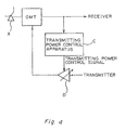
- the output from selector 6 is provided to an amplifier D for performing a power amplification of a transmitting signal from a transmitter (not shown).
- the transmitting power control signal from the transmitting power control apparatus C, shown in Figure 4 is further transmitted from the antenna X through an orthogonal mode transducer.
- two mode operation units for obtaining an up-link rain attenuation amount performs operations independently from each other.
- the outputs of these two mode operating units are selected by selector 6 depending on whether or not the originating unit returning wave can be used for the measurement. Therefore, there is a problem that the transmitting control power becomes discontinuous upon switching the power of selector 6.
- An object of the present invention is to avoid a discontinuous transmitting control power even for an up-link rain attenuation amount obtained through respective arithmetic operations by using two modes of the arithmetic operation, thereby making transmitting power to a communication satellite constant.
- a feature of the present invention resides in a transmitting power control system, a first measuring unit for measuring degradation amount of a returning signal quality of the up link and down link by using the originating station returning wave, a second measurement unit for measuring the down link rain attenuation amount by using a beacon wave, a first mode arithmetic operation unit for always arithmetically operating on an actual up-link rain attenuation amount based on the returning degradation attenuation amount and the down link rain attenuation amount and arithmetically operating a ratio of said actual up-link rain attenuation amount to said down link rain attenuation amount, a measurement executable judgement unit for judging whether or not the measurement is possible based on the originating station returning wave, a second mode arithmetic operating unit for presuming and arithmetically operating the up-link rain attenuation amount based on the rain attenuation amount ratio and the down-link rain attenuation amount by latching the rain attenuation amount ratio when said measurement executable judgement
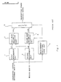
- Figure 5 which shows a principle block diagram of the present invention
- measurement units 1 and 2 measurement executable judging unit 4 and selector 6 are the same as in the prior art shown in Figure 1.
- first mode arithmetic operating unit 7 and second mode arithmetic operating unit 8 are different.
- an up-link rain attenuation amount Lu A is theoretically obtained in accordance with equation (1) in first mode arithmetic operating unit 7, based on degradation amount of the returning wave quality L T obtained from first measurement unit 1 and a down link rain attenuation amount Ld obtained from the second measurement unit 2.
- the ratio Lu A /Ld of the up-link rain attenuation amount Lu A to the down-link rain attenuation amount Ld from the second measurement unit 2 is then arithmetically operated and provided to second mode arithmetic operating unit 8.
- second mode arithmetic operating unit 8 latches the most recent ratio Lu A /Ld provided by first mode arithmetic operating unit 7 based on the signals from measurement executable judging unit 4 to determine a constant K in the above recited equation (2) and multiplies K by the down link rain attenuation amount Ld which changes with time, thereby performing a presumed arithmetic operation of the up-link rain attenuation amount Lu B after the measurement is judged as being impossible to measure.
- selector 6 selects the oiutput of the first mode arithmetic operating unit.
- the measurement is judged to be impossible, it switches from the output of first mode arithmetic operating unit 7 to the output of second mode arithmetic operating unit 8, thereby enabling a transmitting control power signal to be generated.
- the output of the second mode arithmetic operating unit 8 complies with Lu A upon a switching of the mode. Therefore, an assumed arithmetic operation of the up-link rain attenuation amount can be carried out while maintaining measurement continuity after the switching mode is changed from the ouput of first mode arithmetic operating unit 7 to second mode arithmetic operating unit 8.
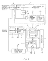
- Figure 6 shows the entire structure of an embodiment of the transmitting power control system according to the present invention uses the demodulation DEM and the measurement executable judging unit 4 produces a signal designating the measurement (receipt) of the possible/impossible designating signal based on whether or not the AFC of the demodulator can be accurately followed.
- First measurement unit 1 comprises a decoder (DEC) 11 for performing an error and decoding a digital demodulation signal containing a bit error in the originating station returning wave A transmitted from demodulator 4 and providing it as a main signal to a receiver (not shown), an encoder (COD) 12 for coding the main signal, an EXOR gate 13 for detecting a coincidence between a signal coded by coder 12 and the output of demodulator 4 before decoding to obtain an error bit, a BER measurement unit 14 for measuring bit error rate (BER) by using an error bit obtained from gate 13, and L T calculating unit 15 for calculating a returning total rain degradation amount L T of the originating station returning wave from a bit error rate and C/N (the predetermined ratio of the carrier wave/noise) in clear weather to provide the total rain degradation amount L T to the first mode operating unit 7.
- DEC decoder
- COD encoder
- EXOR gate 13 for detecting a coincidence between a signal coded by coder 12 and the output of de
- Second measurement unit 2 comprises a receiver 21 for receiving a beacon wave B, and an Ld calculating unit 22 for calculating a down-link rain attenuation amount Ld by comparing the C/N of a beacon wave received from receiver 21 with a predetermined C/N for clear weather.
- Ld calculating unit 22 for calculating a down-link rain attenuation amount Ld by comparing the C/N of a beacon wave received from receiver 21 with a predetermined C/N for clear weather.
- the first mode arithmetic operating unit 7 comprises a first mode up-link rain attenuation amount arithmetic operating unit 71 for calculating a rain attenuation amount Lu A for an up-link from the above equation (1) based on a returning rain degradation amount L T calculated from first measurement unit 1 and a rain attenuation amount Ld for a down-link calculated by second measurement unit 2, and up-link/down-link attentuation amount ratio arithmetic operating unit 72 for arithmetically obtaining the ratio Lu A /Ld, namely, the ratio of the calculated up-link rain attenuation amount Lu A to down-link rain attenuation amount Ld.
- Second mode arithmetic operating unit 8 comprises latch circuit 81 for latching the ratio Lu A /Ld obtained from arithmetic operating unit 72 by using the measurement executable judging signal obtained from measurement executable judging unit 4 and multiplier 82 for multiplying the output of latch circuit 81 with the down link rain attenuation amount Ld.
- First mode up-link rain attenuation amount arithmetic operating unit 71 in first mode arithmetically operating unit 7 receives the returning rain degradation amount L T calculated by first measurement unit 1 and the down link rain attenuation amount Ld calculated by second measurement unit 2. It then transmits the originating unit returning wave up-link rain attenuation amount Lu A to selector 6 as in the prior art and up-link/down link attenuation amount ratio calculating unit 72 continusouly arithmetically obtains ratios Lu A /Ld and transmits them to latch circuit 81.
- Measurement executable judging unit 4 judges, because of the narrow measurement scope of the originating station returning wave, that the measurement is impossible.
- Multiplier 82 multiplies the down-link rain attenuation amount Ld by the ratio K, thus obtaining the up-link rain attenuation amount Lu B from the down link, and thereby providing it to selector 6.
- selector 6 selects the output signal from multiplier 82 as the control signal from measurement executable judging unit 4 designates that the measurement is impossible.
- the multiplier output Ld is equal to the up link rain attenuation amount Lu A from the first mode arithmetic operation unit 7.
- Ld of the ratio K is equal to the down link rain attentuation Ld obtained from second measurement unit 2.
- the rain attenuation amount Ld for the down link outputted from second measurement unit 2 varies and thus the up-link rain attenuation amount K ⁇ Ld is outputted.
- selector 6 When measurement of the originating station returning wave A becomes possible, selector 6 again outputs the up link rain attenuation amount Lu A of the output of the first mode arithmetic operation unit 7 as a transmission power control signal and the above operation is repeated.
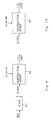
- FIG 7 shows a block diagram of a basic structure of BER measuring unit 14 of the embodiment
- BER measuring unit 14 comprises a first counter 31 for counting an error pulse outputted from EOR gate 13 in Figure 6, a second counter 32 for counting the total number of pulses during the period in which the bit error rate is measured, and a bit error rate arithmetic operating unit 33 for obtaining a bit error ratio based on the output of the two counters.
- Figure 8 shows a detailed block diagram of BER measurement unit 14.
- the bit error rate (BER) is expressed in the exponent representation X x 2 Y /228 to measure the ratio in a stretch from 10 ⁇ 2 to 10 ⁇ 6.
- a converter 40 is actually provided at the output side. This simplifies the hardware by decreasing the total number of pulses to be counted by the second pulse counter shown in Figure 7 to less than 228.
- the number of error pulses to be counted by first counter 31 is latched at latch circuit 34 at a ripple carry outputted from second counter 32.
- the output of latch circuit 34 is converted to a serial signal by parallel/serial converting circuit 35 and the output is input to shift register 36 in a shifting manner from LSB to MSB.
- the shifting operation is controlled by a clock signal (CLK).
- a reverse signal obtained by reversing an output from the MSB of shift register 36 by inverter 7 is input to AND circuit 38 together with a clock signal.
- the shifting operation is cpmtomied until the content of MSB of shift register 36 becomes "1".
- the content of down counter 39 is subjected to a down counting by the number of clocks and the value of the converter 40 is added to the output y′ of down counter 39 to be outputted as a value of y and the content of shift register is outputted as x when the content of MSB from shift register 36 becomes "1".
- the second counter 32 is an 18 bit counter
- FIG 9 is a structural block diagram of the returning total rain degradation amount (L T ) calculating unit 15 shown in Figure 6.
- L T calculating unit 15 calculates a returning total rain degradation amount L T by using a bit error rate outputted from BER measurement unit 14 and carrier wave/noise ratio (C/N) for clear weather.
- the bit error rate (BER) has a one-to-one relationship with the corresponding current carrier wave/noise ratio (C/N)T. This relationship is stored in read only memory 41 in Figure 9.
- the output of BER measurement unit 14 is input to read only memory 41, thereby providing the current total carrier wave/noise ratio (C/N)T.
- the returning total rain degradation amount L T of the originating station returning wave is given by the following equation.
- L T (C/N) To /(C/N) T (3)
- (C/N) To represents the total carrier wave/noise ratio for clear weather and this is known.
- the units of equation (3) is expressed in "dB"
- the total rain degradation amount L T is obtained by subtracting the current carrier wave/noise ratio from the carrier wave/noise ratio for clear weather, by using subtraction adder 42 shown in Figure 9.
- FIG 10 shows a block diagram of the down-link rain attenuation amount (Ld) calculation unit 22 of Figure 6.
- Subtractor adder 43 in Figure 10 subtracts the current carrier wave/noise ratio (C/N)d from the carrier wave/noise ratio (C/N)do upon the clear weather in accordance with equation (4), thereby outputting the rain attenuation amount Ld of the down link wave.
- Figure 11 shows a structural block diagram of the first mode up-link rain attenuation amount (Lu A ).
- First mode up-link rain attenuation amount arithmetic operation unit 71 arithmetically obtains the up-link rain degradation amount by using total returning rain attenuation amount L T of the originating station returning wave outputted from L T calculating unit 15.
- the down-link rain attenuation amount Ld of the beacon wave outputted from the down-link rain attenuation amount calculating unit 22 and equation (1) representing the above arithmetic operation can be provided according to the final form of the equation as follows.
- T represents an increased amount of the current power as compared with the transmitting power upon measuring the C/N in clear weather
- (C/N) uo ⁇ 1 is the inverse C/N of the up link for clear weather
- A is a ratio (constant) of an inverse of C/N of the down link for clear weather to the inverse of C/N of the beacon wave for the clear weather.
- (C/N) d ⁇ 1 calculating unit 44 in Figure 11 arithmetically obtains the inverse of carrier wave/noise ratio of the current down link based on the value of Ld outputted from Ld calculating unit 22.
- the input to Ld calculating unit 22 is (C/N) d . Therefore, the inverse can be obtained by inverter 45.
- the output of (C/N) d ⁇ 1 calculating unit 44 is added to a constant A by adder 46, as shown in the second term of the denominator of the fraction in equation (5), and then the sum of the added value and the inverse of carrier wave/noise ratio of the up link for clear weather is obtained from read only memory 47.
- the ouput from BER measurement unit 14 in Figure 6 is provided to L T calculating unit 15 and the output thereof is applied to Lu A calculating unit 71.
- the output of Lu A calculating unit 71 is applied to (C/N) T ⁇ 1 calculating unit 48 and as a result provides the inverse of (C/N) T to be inputted to subtractor adder 42 of L T calculating unit 15 shown in Figure 9.
- read only memory 49 may be employed to directly obtain the inverse value from the bit error rate (BER) outputted from BER measurement unit 14.
- Adder 50 adds the inverse of the denominator of equation(5) outputted from read only memory 47, from (C/N)d ⁇ 1 calculation unit 44 or from read only memory 49. Furthermore, adder 51 adds the value of T shown in equation (5) to the output of adder 50, thereby outputting the first mode up link rain attenuation amount Lu A .
- Figure 12 is a block diagram of an up-link/down-link attenuation amount ratio (Lu A /Ld) arithmetic operating unit.
- the arithmetic operating unit in Figure 6 outputs a ratio of the first mode up-link rain attenuation amount Lu A to down-link rain attenuation amount Ld and this ratio can be outputted as shown in Fig. 12 by obtaining the difference between Lu A and Ld using "dB" as the unit.
- the attenuation amount ratio of the actual up-link rain attenuation amount to the down-link rain degradation amount, which is obtained by the returning rain degradation amount and down-link rain degradation amount in the first mode arithmetic opeation unit 7 is always and continuously subjected to the arithmetic operation.
- the measurement executable judgement unit judges that the measurement is impossible, the up-link rain degradation amount is presumed and calculated from the rain degradation amount ratio and the down-link rain degradation amount by the second mode arithmetic operation unit when the rain degradation amount ratio is latched, thereby providing the output.
- the transmitting power control value when a mode is switched, the transmitting power control value is not discontinuous and the good accuracy of the up-link rain degradation amount obtained by the originating station returning wave reflects on the accuracy of the up-link rain degradation amount presumed by the beacon wave after the mode is switched. Therefore, the accuracy of the up-link rain attenuation amount obtained by the beacon wave can be improved.
- the present transmitting power control system can provide constant power to a satellite and is useful for a satellite communication system.
Landscapes
- Engineering & Computer Science (AREA)
- Computer Networks & Wireless Communication (AREA)
- Signal Processing (AREA)
- Radio Relay Systems (AREA)
- Cable Transmission Systems, Equalization Of Radio And Reduction Of Echo (AREA)
- Transmitters (AREA)
Applications Claiming Priority (2)
| Application Number | Priority Date | Filing Date | Title |
|---|---|---|---|
| JP56760/89 | 1989-03-09 | ||
| JP1056760A JP2551650B2 (ja) | 1989-03-09 | 1989-03-09 | 送信電力制御方式 |
Publications (2)
| Publication Number | Publication Date |
|---|---|
| EP0389848A2 true EP0389848A2 (de) | 1990-10-03 |
| EP0389848A3 EP0389848A3 (de) | 1991-12-11 |
Family
ID=13036454
Family Applications (1)
| Application Number | Title | Priority Date | Filing Date |
|---|---|---|---|
| EP19900104526 Ceased EP0389848A3 (de) | 1989-03-09 | 1990-03-09 | Sendeleistungsregelsystem |
Country Status (3)
| Country | Link |
|---|---|
| US (1) | US5060292A (de) |
| EP (1) | EP0389848A3 (de) |
| JP (1) | JP2551650B2 (de) |
Cited By (5)
| Publication number | Priority date | Publication date | Assignee | Title |
|---|---|---|---|---|
| RU2156545C2 (ru) * | 1995-09-08 | 2000-09-20 | Квэлкомм Инкорпорейтед | Способ управления действительной мощностью передачи базовой станции в сотовой системе связи и устройство для его осуществления |
| WO2001048968A1 (en) * | 1999-12-28 | 2001-07-05 | Ericsson Inc. | Method of reporting signal quality measurements from a mobile terminal with enhanced demodulation algorithm |
| RU2172070C1 (ru) * | 1998-06-18 | 2001-08-10 | Самсунг Электроникс Ко., Лтд | Устройство и способ для связи сигналов управления мощностью в подвижной системе связи |
| EP0825730A3 (de) * | 1996-08-21 | 2003-10-08 | Hughes Electronics Corporation | Verfahren und Anordnung zur Sendeleistungssteuerung in einer Aufwärtsverbindung in einer Satellitenkommunikationsanordnung mit hoher Datenrate und An-Bord-De- und Remodulation |
| EP1049269A3 (de) * | 1999-04-29 | 2003-10-15 | Hughes Electronics Corporation | Satelliten Übertragungsanordnung mit adaptive Kompensation des Übertragungsverlust |
Families Citing this family (20)
| Publication number | Priority date | Publication date | Assignee | Title |
|---|---|---|---|---|
| US5204970A (en) * | 1991-01-31 | 1993-04-20 | Motorola, Inc. | Communication system capable of adjusting transmit power of a subscriber unit |
| JP3269577B2 (ja) * | 1991-10-02 | 2002-03-25 | モトローラ・インコーポレイテッド | ビット誤り率検出方法 |
| AU664111B2 (en) * | 1992-07-09 | 1995-11-02 | Spacial Communications Pty. Ltd. | Method for determining design parameters |
| WO1994001940A1 (en) * | 1992-07-09 | 1994-01-20 | Spacial Communications Pty. Ltd. | Method for determining design parameters |
| JPH0946286A (ja) * | 1995-08-02 | 1997-02-14 | Fujitsu Ltd | 衛星通信地球局における送信電力制御装置 |
| JP2755241B2 (ja) * | 1995-08-25 | 1998-05-20 | 住友電気工業株式会社 | 無線中継器用発振検出装置およびこの装置が適用された無線中継器 |
| US5828335A (en) * | 1995-11-06 | 1998-10-27 | Martin Marietta Corporation | Spacecraft communication channel power control system |
| US5708966A (en) * | 1996-04-04 | 1998-01-13 | Lockheed Martin Corporation | Method and apparatus for performing power control using the wide-band synchronization |
| US5754942A (en) * | 1996-09-09 | 1998-05-19 | Hughes Electronics Corporation | Satellite power level monitoring system and method using digital signal processing |
| US6212360B1 (en) * | 1997-04-09 | 2001-04-03 | Ge Capital Spacenet Services, Inc. | Methods and apparatus for controlling earth-station transmitted power in a VSAT network |
| US6070051A (en) * | 1997-11-03 | 2000-05-30 | Motorola, Inc. | Method and apparatus for predicting service availability for a ground-to-satellite radio of a communication system |
| US6141534A (en) * | 1998-03-25 | 2000-10-31 | Spacecode Llc | Communication satellite system with dynamic downlink resource allocation |
| US6321065B1 (en) * | 1998-10-30 | 2001-11-20 | Trw Inc. | Performance enhancement of open-loop power control for satellite communication systems |
| US6813476B1 (en) | 2000-11-13 | 2004-11-02 | Andrew Corporation | Method and system for compensating for atmospheric fading in a communications system |
| JP3988392B2 (ja) * | 2001-01-24 | 2007-10-10 | 日本電気株式会社 | 携帯無線端末、afc制御方法及びafc制御プログラム |
| US7047029B1 (en) * | 2001-09-10 | 2006-05-16 | The Directv Group, Inc. | Adaptive transmission system |
| US9485010B1 (en) | 2001-09-10 | 2016-11-01 | The Directv Group, Inc. | Adaptive coding and modulation for spot beam satellite broadcast |
| US7653349B1 (en) | 2003-06-18 | 2010-01-26 | The Directv Group, Inc. | Adaptive return link for two-way satellite communication systems |
| US7949342B2 (en) * | 2004-01-08 | 2011-05-24 | Interdigital Technology Corporation | Radio resource management in wireless local area networks |
| US10582262B2 (en) | 2016-06-30 | 2020-03-03 | At&T Intellectual Property I, L.P. | Satellite video content delivery system |
Family Cites Families (6)
| Publication number | Priority date | Publication date | Assignee | Title |
|---|---|---|---|---|
| DE3273703D1 (en) * | 1981-11-16 | 1986-11-13 | Nec Corp | Earth station transmission power control system |
| JPS60190035A (ja) * | 1984-03-09 | 1985-09-27 | Nec Corp | 衛星通信送信電力制御方式 |
| US4896369A (en) * | 1984-12-28 | 1990-01-23 | Harris Corporation | Optimal satellite TWT power allocation process for achieving requested availability and maintaining stability in ALPC-type networks |
| JPS6261431A (ja) * | 1985-09-12 | 1987-03-18 | Kokusai Denshin Denwa Co Ltd <Kdd> | 送信電力制御方式 |
| JPS6346824A (ja) * | 1986-08-14 | 1988-02-27 | Kokusai Denshin Denwa Co Ltd <Kdd> | 送信電力制御方式 |
| US4941199A (en) * | 1989-04-06 | 1990-07-10 | Scientific Atlanta | Uplink power control mechanism for maintaining constant output power from satellite transponder |
-
1989
- 1989-03-09 JP JP1056760A patent/JP2551650B2/ja not_active Expired - Lifetime
-
1990
- 1990-03-08 US US07/490,249 patent/US5060292A/en not_active Expired - Fee Related
- 1990-03-09 EP EP19900104526 patent/EP0389848A3/de not_active Ceased
Cited By (6)
| Publication number | Priority date | Publication date | Assignee | Title |
|---|---|---|---|---|
| RU2156545C2 (ru) * | 1995-09-08 | 2000-09-20 | Квэлкомм Инкорпорейтед | Способ управления действительной мощностью передачи базовой станции в сотовой системе связи и устройство для его осуществления |
| EP0825730A3 (de) * | 1996-08-21 | 2003-10-08 | Hughes Electronics Corporation | Verfahren und Anordnung zur Sendeleistungssteuerung in einer Aufwärtsverbindung in einer Satellitenkommunikationsanordnung mit hoher Datenrate und An-Bord-De- und Remodulation |
| RU2172070C1 (ru) * | 1998-06-18 | 2001-08-10 | Самсунг Электроникс Ко., Лтд | Устройство и способ для связи сигналов управления мощностью в подвижной системе связи |
| EP1049269A3 (de) * | 1999-04-29 | 2003-10-15 | Hughes Electronics Corporation | Satelliten Übertragungsanordnung mit adaptive Kompensation des Übertragungsverlust |
| WO2001048968A1 (en) * | 1999-12-28 | 2001-07-05 | Ericsson Inc. | Method of reporting signal quality measurements from a mobile terminal with enhanced demodulation algorithm |
| US6449464B1 (en) | 1999-12-28 | 2002-09-10 | Ericsson Inc. | Method of reporting signal quality measurements from a mobile terminal with enhanced demodulation algorithm |
Also Published As
| Publication number | Publication date |
|---|---|
| EP0389848A3 (de) | 1991-12-11 |
| JPH02235445A (ja) | 1990-09-18 |
| US5060292A (en) | 1991-10-22 |
| JP2551650B2 (ja) | 1996-11-06 |
Similar Documents
| Publication | Publication Date | Title |
|---|---|---|
| US5060292A (en) | Transmitting power control system | |
| US5214687A (en) | Method to determine transmission quality | |
| US6226505B1 (en) | Automatic frequency correction apparatus and method for radio calling system | |
| RU2138909C1 (ru) | Способ и устройство для оценки качества канала в приемнике | |
| US5630210A (en) | Method and apparatus for determining signal transmission quality levels of a transmitted signal | |
| US5203026A (en) | Method of selecting the most suitable receiver antenna from two or more receiver antennas | |
| EP0632911B1 (de) | Fehlerdetektorschaltung und Verfahren für Empfänger zum Empfang von Diskretkodierten Signalen | |
| US5944844A (en) | Method for determining connection quality in a receiver utilizing a Viterbi decoder | |
| JPH06102299A (ja) | Cn比測定装置 | |
| EP0419432B1 (de) | Methode zur Erzeugung von Qualitätsfaktoren für binäre Zahlen erhalten durch Viterbi-Analyse eines Signals | |
| JPS58182356A (ja) | ビツト誤り率測定方式 | |
| EP0411756A2 (de) | Funkfernsprechempfänger mit Verstärkungsregelung | |
| US6487174B1 (en) | S/N measuring circuit and method, transmitting electric power control apparatus and digital communicating system | |
| US4296495A (en) | Device for measuring the quality of a digital radio link | |
| US4103108A (en) | Circuit and method for digitally measuring signal levels of pcm encoded signals | |
| SU926779A2 (ru) | Устройство дл определени оптимальных рабочих частот | |
| CA1068408A (en) | Circuit and method for digitally measuring signal levels, of pcm encoded signals | |
| JPH02230834A (ja) | 符号誤り率測定方式 | |
| RU2011300C1 (ru) | Многопараметрическая адаптивная цифровая система радиосвязи | |
| SU922855A1 (ru) | Устройство для адаптивной коммутации 1 | |
| KR0158117B1 (ko) | 비트에러율 예측기 | |
| SU868611A1 (ru) | Многодиапазонное устройство измерени частоты | |
| CA2413934C (en) | S/n measuring circuit and method, transmitting electric power control apparatus and digital communicating system | |
| JPH05284077A (ja) | 移動通信用一周波数交互通信方式におけるダイバーシチ方式 | |
| SU678683A1 (ru) | Устройство дл контрол состо ни канала св зи с частотной или фазовой модул цией |
Legal Events
| Date | Code | Title | Description |
|---|---|---|---|
| PUAI | Public reference made under article 153(3) epc to a published international application that has entered the european phase |
Free format text: ORIGINAL CODE: 0009012 |
|
| AK | Designated contracting states |
Kind code of ref document: A2 Designated state(s): DE GB IT |
|
| PUAL | Search report despatched |
Free format text: ORIGINAL CODE: 0009013 |
|
| AK | Designated contracting states |
Kind code of ref document: A3 Designated state(s): DE GB IT |
|
| 17P | Request for examination filed |
Effective date: 19920213 |
|
| 17Q | First examination report despatched |
Effective date: 19931223 |
|
| STAA | Information on the status of an ep patent application or granted ep patent |
Free format text: STATUS: THE APPLICATION HAS BEEN REFUSED |
|
| 18R | Application refused |
Effective date: 19960118 |