EP0390525A2 - Optisch gepumpte Festkörper-Laservorrichtung mit einer Halbleiter-Laservorrichtung - Google Patents
Optisch gepumpte Festkörper-Laservorrichtung mit einer Halbleiter-Laservorrichtung Download PDFInfo
- Publication number
- EP0390525A2 EP0390525A2 EP90303289A EP90303289A EP0390525A2 EP 0390525 A2 EP0390525 A2 EP 0390525A2 EP 90303289 A EP90303289 A EP 90303289A EP 90303289 A EP90303289 A EP 90303289A EP 0390525 A2 EP0390525 A2 EP 0390525A2
- Authority
- EP
- European Patent Office
- Prior art keywords
- light
- laser
- semiconductor laser
- solid
- wavelength
- Prior art date
- Legal status (The legal status is an assumption and is not a legal conclusion. Google has not performed a legal analysis and makes no representation as to the accuracy of the status listed.)
- Granted
Links
- 239000004065 semiconductor Substances 0.000 title claims abstract description 81
- 230000003287 optical effect Effects 0.000 title claims abstract description 40
- 238000001514 detection method Methods 0.000 claims description 11
- 238000005086 pumping Methods 0.000 abstract description 9
- 238000002835 absorbance Methods 0.000 abstract 1
- 238000010586 diagram Methods 0.000 description 6
- 229910009372 YVO4 Inorganic materials 0.000 description 4
- 239000000463 material Substances 0.000 description 3
- 238000006243 chemical reaction Methods 0.000 description 2
- 238000010276 construction Methods 0.000 description 2
- 239000013078 crystal Substances 0.000 description 2
- 230000007423 decrease Effects 0.000 description 2
- 230000031700 light absorption Effects 0.000 description 2
- 230000001105 regulatory effect Effects 0.000 description 2
- 230000003247 decreasing effect Effects 0.000 description 1
- 230000007812 deficiency Effects 0.000 description 1
- 230000006866 deterioration Effects 0.000 description 1
- 238000005259 measurement Methods 0.000 description 1
- 238000012986 modification Methods 0.000 description 1
- 230000004048 modification Effects 0.000 description 1
- 239000013307 optical fiber Substances 0.000 description 1
- 238000002310 reflectometry Methods 0.000 description 1
- 229910052710 silicon Inorganic materials 0.000 description 1
- 239000010703 silicon Substances 0.000 description 1
- 230000003595 spectral effect Effects 0.000 description 1
- 238000001228 spectrum Methods 0.000 description 1
- 230000001360 synchronised effect Effects 0.000 description 1
Images
Classifications
-
- H—ELECTRICITY
- H01—ELECTRIC ELEMENTS
- H01S—DEVICES USING THE PROCESS OF LIGHT AMPLIFICATION BY STIMULATED EMISSION OF RADIATION [LASER] TO AMPLIFY OR GENERATE LIGHT; DEVICES USING STIMULATED EMISSION OF ELECTROMAGNETIC RADIATION IN WAVE RANGES OTHER THAN OPTICAL
- H01S5/00—Semiconductor lasers
- H01S5/06—Arrangements for controlling the laser output parameters, e.g. by operating on the active medium
- H01S5/068—Stabilisation of laser output parameters
- H01S5/0683—Stabilisation of laser output parameters by monitoring the optical output parameters
-
- H—ELECTRICITY
- H01—ELECTRIC ELEMENTS
- H01S—DEVICES USING THE PROCESS OF LIGHT AMPLIFICATION BY STIMULATED EMISSION OF RADIATION [LASER] TO AMPLIFY OR GENERATE LIGHT; DEVICES USING STIMULATED EMISSION OF ELECTROMAGNETIC RADIATION IN WAVE RANGES OTHER THAN OPTICAL
- H01S3/00—Lasers, i.e. devices using stimulated emission of electromagnetic radiation in the infrared, visible or ultraviolet wave range
- H01S3/09—Processes or apparatus for excitation, e.g. pumping
- H01S3/091—Processes or apparatus for excitation, e.g. pumping using optical pumping
- H01S3/094—Processes or apparatus for excitation, e.g. pumping using optical pumping by coherent light
- H01S3/0941—Processes or apparatus for excitation, e.g. pumping using optical pumping by coherent light of a laser diode
- H01S3/09415—Processes or apparatus for excitation, e.g. pumping using optical pumping by coherent light of a laser diode the pumping beam being parallel to the lasing mode of the pumped medium, e.g. end-pumping
-
- H—ELECTRICITY
- H01—ELECTRIC ELEMENTS
- H01S—DEVICES USING THE PROCESS OF LIGHT AMPLIFICATION BY STIMULATED EMISSION OF RADIATION [LASER] TO AMPLIFY OR GENERATE LIGHT; DEVICES USING STIMULATED EMISSION OF ELECTROMAGNETIC RADIATION IN WAVE RANGES OTHER THAN OPTICAL
- H01S3/00—Lasers, i.e. devices using stimulated emission of electromagnetic radiation in the infrared, visible or ultraviolet wave range
- H01S3/09—Processes or apparatus for excitation, e.g. pumping
- H01S3/091—Processes or apparatus for excitation, e.g. pumping using optical pumping
- H01S3/094—Processes or apparatus for excitation, e.g. pumping using optical pumping by coherent light
- H01S3/09408—Pump redundancy
-
- H—ELECTRICITY
- H01—ELECTRIC ELEMENTS
- H01S—DEVICES USING THE PROCESS OF LIGHT AMPLIFICATION BY STIMULATED EMISSION OF RADIATION [LASER] TO AMPLIFY OR GENERATE LIGHT; DEVICES USING STIMULATED EMISSION OF ELECTROMAGNETIC RADIATION IN WAVE RANGES OTHER THAN OPTICAL
- H01S3/00—Lasers, i.e. devices using stimulated emission of electromagnetic radiation in the infrared, visible or ultraviolet wave range
- H01S3/10—Controlling the intensity, frequency, phase, polarisation or direction of the emitted radiation, e.g. switching, gating, modulating or demodulating
- H01S3/13—Stabilisation of laser output parameters, e.g. frequency or amplitude
- H01S3/131—Stabilisation of laser output parameters, e.g. frequency or amplitude by controlling the active medium, e.g. by controlling the processes or apparatus for excitation
- H01S3/1312—Stabilisation of laser output parameters, e.g. frequency or amplitude by controlling the active medium, e.g. by controlling the processes or apparatus for excitation by controlling the optical pumping
-
- H—ELECTRICITY
- H01—ELECTRIC ELEMENTS
- H01S—DEVICES USING THE PROCESS OF LIGHT AMPLIFICATION BY STIMULATED EMISSION OF RADIATION [LASER] TO AMPLIFY OR GENERATE LIGHT; DEVICES USING STIMULATED EMISSION OF ELECTROMAGNETIC RADIATION IN WAVE RANGES OTHER THAN OPTICAL
- H01S5/00—Semiconductor lasers
- H01S5/02—Structural details or components not essential to laser action
- H01S5/024—Arrangements for thermal management
- H01S5/02407—Active cooling, e.g. the laser temperature is controlled by a thermo-electric cooler or water cooling
- H01S5/02415—Active cooling, e.g. the laser temperature is controlled by a thermo-electric cooler or water cooling by using a thermo-electric cooler [TEC], e.g. Peltier element
-
- H—ELECTRICITY
- H01—ELECTRIC ELEMENTS
- H01S—DEVICES USING THE PROCESS OF LIGHT AMPLIFICATION BY STIMULATED EMISSION OF RADIATION [LASER] TO AMPLIFY OR GENERATE LIGHT; DEVICES USING STIMULATED EMISSION OF ELECTROMAGNETIC RADIATION IN WAVE RANGES OTHER THAN OPTICAL
- H01S5/00—Semiconductor lasers
- H01S5/06—Arrangements for controlling the laser output parameters, e.g. by operating on the active medium
- H01S5/068—Stabilisation of laser output parameters
- H01S5/0683—Stabilisation of laser output parameters by monitoring the optical output parameters
- H01S5/06837—Stabilising otherwise than by an applied electric field or current, e.g. by controlling the temperature
-
- H—ELECTRICITY
- H01—ELECTRIC ELEMENTS
- H01S—DEVICES USING THE PROCESS OF LIGHT AMPLIFICATION BY STIMULATED EMISSION OF RADIATION [LASER] TO AMPLIFY OR GENERATE LIGHT; DEVICES USING STIMULATED EMISSION OF ELECTROMAGNETIC RADIATION IN WAVE RANGES OTHER THAN OPTICAL
- H01S5/00—Semiconductor lasers
- H01S5/06—Arrangements for controlling the laser output parameters, e.g. by operating on the active medium
- H01S5/068—Stabilisation of laser output parameters
- H01S5/0683—Stabilisation of laser output parameters by monitoring the optical output parameters
- H01S5/0687—Stabilising the frequency of the laser
Definitions
- the present invention relates to an optical pumping-type solid-state laser apparatus with a semiconductor laser device, in which the solid-state laser is optically pumped by a laser beam with a predetermined wavelength emitted from the semiconductor laser device so as to generate a laser beam with a target wavelength.
- a conventional solid-state laser is optically pumped by light emitted from a flash lamp so as to generate a laser beam.
- many solid-state lasers such as Nd-doped YAG lasers efficiently absorb light with only a short range of wavelengths. Since the light emitted from the flash lamp has a wide variety of wavelengths, only a small part of the light thereof is absorbed by the solid-state laser. Thus, this type of solid-state laser has low efficiency of conversion of light from the light source into a final laser beam.
- laser light emitted from a semiconductor laser device has a similar range of wavelengths to that of the light efficiently absorbed by the solid-state laser mentioned above.
- the use of such a semiconductor laser device as a light source for optical pumping attains higher efficiency in the conversion of the light from the light source into a final laser beam.
- an optical pumping-type solid-state laser apparatus which utilizes a semiconductor laser device as a light source for optically pumping the solid-state laser for the generation of a desired laser beam has been developed.
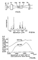
- FIG. 5 shows a conventional optical pumping-type solid-state laser apparatus with a semiconductor laser device.
- the semiconductor laser device 61 is mounted on a temperature regulator 67 , which modifies the wavelength of the laser light to be emitted from the semiconductor laser device 61 .
- the laser beam emitted from the semiconductor laser device 61 is directed through a light-converging unit 62 onto a light-receiving facet 63a of a YAG rod 63 .
- a reflecting mirror 64 facing a light-emitting facet 63b of the YAG rod 63 .
- the light-receiving facet 63a of the YAG rod 63 and the reflecting mirror 64 constitute a laser resonator.
- the YAG rod 63 absorbs laser light emitted from the semiconductor laser device 61 and is optically pumped by the laser light so as to generate a laser beam with a wavelength of 1.064 ⁇ m.
- Figure 6a shows the light-absorption characteristics of the YAG rod 63 with respect to wavelengths of light.
- the YAG rod 63 absorbs light with a wavelength of 0.809 ⁇ m at high efficiency.
- the semiconductor laser device 61 which can emit a laser beam with the wavelength of 0.809 ⁇ m, is used for optically pumping the YAG rod 63 .
- the light-receiving facet 63a of the YAG rod 63 is coated with a film which transmits light with a wavelength of 0.809 ⁇ m and reflects light with a wavelength of 1.064 ⁇ m.
- the light-emitting facet 63b facing the reflecting mirror 64 is coated with a film which transmits light with the wavelength of 1.064 ⁇ m.
- the surface of the reflecting mirror 64 which faces the light-emitting facet 63b is coated with a reflecting film for reflecting light with the wavelength of 1.064 ⁇ m at a high reflectivity.
- the temperature regulator 67 regulates the temperature of the semiconductor laser device 61 so that the laser light to be emitted therefrom has the wavelength of 0.809 ⁇ m, which can be absorbed by the YAG rod 63 at high efficiency as described above.
- the laser beam emitted from the semiconductor laser device 61 is efficiently absorbed by the YAG rod 63 , which is then optically pumped by the laser light to generate therein a laser beam with a wavelength of 1.064 ⁇ m. Then, the resultant laser beam is emitted therefrom at a high output level.
- An optical pumping-type solid-state laser apparatus with the above configuration has been developed as a small-sized laser light source for laser instrumentaion and measurement, laser material processing, and the like.
- mode hopping or the like may arise due to deterioration with time, changes in temperature or in the level of the injected current, and the like.
- a semiconductor laser device which can output a laser beam with a desired wavelength is carefully selected, the wavelength thereof tends to change for the above-mentioned reason, and accordingly deviates from the short range of wavelengths of light which can be absorbed at high efficiency by the YAG rod 63 .
- This deviation changes the amount of the laser light to be absorbed by the YAG rod 63 , thereby changing the resultant optical output power of the solid-state laser apparatus.
- the laser generation efficiency of an Nd-doped YAG rod 63 with respect to the wavelengths of the laser light emitted from a semiconductor laser device 61 is shown in Figure 6b.
- Figure 6b when the wavelength of the laser light deviates from the short range of wavelengths including 0.809 ⁇ m, the output level of the resultant laser beam is greatly decreased.
- the laser light of the semiconductor laser device used in the conventional optical pumping-type solid-state laser apparatus is likely to change in wavelength, which naturally decreases the output level of the resultant laser beam, thereby preventing the solid-state laser apparatus from generating laser light in a stable manner for a long period of time.
- the optical pumping-type solid-state laser apparatus in accordance with the present invention comprises a semiconductor laser device; a solid-state laser which is optically pumped by laser light with a predetermined wavelength emitted from said semiconductor laser device so as to generate laser light with a target wavelength; a first optical detection means for detecting the amount of laser light emitted from said semiconductor laser device; a second optical detection means for detecting the amount of laser light which has been emitted from said semiconductor laser device and transmitted through a filter means, said filter means absorbing light with the same wavelength as that of light to be absorbed by said solid-state laser; and a means for modifying the wavelength of the laser light to be emitted from said semiconductor laser device in accordance with the detected results of said first and second optical detection means.
- the means for modifying the wavelength of the laser light is a temperature regulator which regulates the temperature of said semiconductor laser device.
- the second optical detection means includes a photodetector.
- the second optical detection means may include two photodetectors for detecting the amount of laser light which has been emitted from said semiconductor laser device and transmitted through two respective filter means, said two filter means being arranged to first transmit laser light with two different ranges of wavelengths, respectively, and then absorb light with the same wavelength as that of the light to be absorbed by said solid-state laser, the central value of said two ranges of wavelengths being slightly shifted from each other.
- the solid-state laser may receive laser beams emitted from a plurality of semiconductor laser devices.
- the solid-state laser is a YAG laser.
- the invention described herein makes possible the objective of providing an optical pumping-type solid-state laser apparatus utilizing a semiconductor laser device which emits a laser beam with an accurately adjusted wavelength for optically pumping the solid-state laser, thereby allowing the solid-state laser to stably generate a laser beam at a high output level for a long period of time.
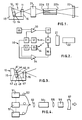
- Figure 1 shows an optical pumping-type solid-state laser apparatus with a semiconductor laser device in accordance with the present invention, which comprises a semiconductor laser section 10 , a light-converging unit 21 , a YAG rod 22 , and a reflecting mirror 23 .
- the semiconductor laser section 10 includes a semiconductor laser device 11 and a temperature regulator 16 , which comprises a Peltier element, for adjusting the wavelength of the laser beam to be emitted from the semiconductor laser device 11 , the semiconductor laser device 11 being mounted on the temperature regulator 16 .
- the laser beam emitted from the semiconductor laser device 11 is converged by the light-converging unit 21 to be directed onto the light-receiving facet 22a of the YAG rod 22 .
- the reflecting mirror 23 facing a light-emitting facet 22b of the YAG rod 22 .
- the light-receiving facet 22a of the YAG rod 22 is coated with a film which transmits light with a predetermined wavelength, for example, of 0.809 ⁇ m, i.e., the wavelength of light that can be absorbed by the YAG rod 22 at high efficiency.
- This film reflects the light to be generated in the YAG rod 22 , i.e., the light with a target wavelength, for example, of 1.064 ⁇ m.
- the light-emitting facet 22b is also coated with a transmitting film which transmits a laser beam with the wavelength of 1.064 ⁇ m generated in the YAG rod 22 .
- the surface of the reflecting mirror 23 is coated with a reflecting film which reflects the laser beam transmitted through the light-emitting facet 22b of the YAG rod 22 , i.e., the laser beam with the wavelength of 1.064 ⁇ m.
- the light-receiving facet 22a of the YAG rod 22 and the reflecting surface of the reflecting mirror 23 constitute a resonator. Since the YAG rod 22 absorbs light with the wavelength of 0.809 ⁇ m at high efficiency, it absorbs a large proportion of the laser beam emitted from the semiconductor laser device 11 , the wavelength of which is carefully adjusted to 0.809 ⁇ m as will be described later in detail. This allows the YAG rod 22 to generate a final laser beam with the wavelength of 1.064 ⁇ m at a high output level.
- the semiconductor laser section 10 also includes first and second photodetectors 12 and 13 consisting of pin photodiodes made of silicon, which are mounted on a supporting member 15 and located at the rear side of the semiconductor laser device 11 , the rear side being opposite to the side provided with the light-converging unit 21 .
- the first and second photodetectors 12 and 13 are disposed adjacent to each other or formed as a single unit.
- the semiconductor laser device 11 also emits a laser beam from its rear side toward the first and second photodetectors 12 and 13 .
- the light-receiving surface of the second photodetector 13 is provided with a filter plate 14 which is made of the same laser material as that of the YAG rod 22 .
- the filter plate 14 absorbs the light with the same wavelength as that of the light absorbed by the YAG rod 22 .
- the first photodetector 12 directly receives the light emitted from the semiconductor laser device 11 , while the second photodetector 13 receives the light through the filter plate 14 .
- FIG. 2 is a block diagram showing a control system of the solid-state laser apparatus of Figure 1.
- the laser beam emitted from the semiconductor laser device 11 is directed through the light-converging unit 21 into the YAG rod 22 , allowing the YAG rod 22 to generate a laser beam with a target wavelength.
- the semiconductor laser device 11 also emits light from its rear side toward the opposite direction, part of which is directly received by the first photodetector 12 , and the other part of which is received by the second photodetector 13 through the filter plate 14 .
- the first and second photodetectors 12 and 13 output electric signals in accordance with the amounts of light they have received.
- the output of the first photodetector 12 which has directly received the laser light is amplified by an amplifier 31 and supplied to one of the two input terminals of the first comparator 33 and also supplied to one of the two input terminals of the second comparator 34 .
- the output of the second photodetector 13 which receives the laser light through the filter plate 14 is amplified by the amplifier 32 and supplied to the other input terminal of the second comparator 34 .
- a standard signal generated by a standard signal generator 35 is supplied to the other input terminal of the first comparator 33 .
- the output of the first comparator 33 is fed to a driving circuit 17 , which controls the semiconductor laser device 11 so that it generates a laser beam with a predetermined output level.
- the output of the second comparator 34 is supplied to the temperature regulator 16 , which regulates the temperature of the semiconductor laser device 11 so as to adjust the wavelength of the laser light to be emitted therefrom.
- the laser beam emitted from the rear side of the semiconductor laser device 11 is received by the first and second photodetectors 12 and 13 .
- the first photodetector 12 directly receives the laser light and outputs a signal in accordance with the amount of light it has received.
- the signal is amplified by the amplifier 31 and then delivered to the first comparator 33 , where it is compared with the standard signal generated by the standard signal generator 35 . If it is determined that the amount of light detected by the first photodetector 12 is equal to or less than the standard level, the first comparator 33 outputs a predetermined signal to the driving circuit 17 , which then drives the semiconductor laser device 11 to output laser light with a predetermined output level.
- the second photodetector 13 receives the laser light through the filter plate 14 which absorbs the light with the same wavelength as that of the light absorbed by the YAG rod 22 .
- the filter plate 14 also absorbs the same large proportion of the laser light, so that only a small amount of light is transmitted therethrough to be received by the second photodetector 13 .
- the wavelength of the laser light of the semiconductor laser device 11 deviates from the range of wavelengths of the light which can be absorbed at high efficiency by the YAG rod 22 , the amount of light absorbed by the YAG rod 22 and accordingly by the filter plate 14 decreases, thereby increasing the amount of light to be received by the second photodetector 13 .
- the second comparator 34 receives signals output from the first and second photodetectors 12 and 13 as described above, and compares these output signals. When the second comparator 34 determines that the difference between the amount of light detected by the first photodetector 12 and that detected by the second photodetector 13 is equal to or less than a predetermined level, it outputs a predetermined signal to the temperature regulator 16 . Upon receiving the predetermined signal, the temperature regulator 16 controls the temperature of the semiconductor laser device 11 so that laser light with an appropriate wavelength (i.e., 0.809 ⁇ m in this embodiment) is emitted therefrom.
- an appropriate wavelength i.e., 0.809 ⁇ m in this embodiment
- the semiconductor laser device 11 constantly emits laser light with a predetermined wavelength which can be efficiently absorbed by the YAG rod 22 . This assures stable generation of a final laser beam at a high output level in the YAG rod 22 .
- the temperature regulator 16 comprising the Peltier element is used to adjust the wavelength of the laser light to be emitted from the semiconductor laser device 11 .
- the wavelength for the adjustment of the wavelength, however, other arrangements can be adopted.
- a complex resonator-type semiconductor laser device may be used as the light source for optical pumping, in which the resonating mode is regulated to adjust the wavelength of the laser light to be emitted.
- Another arrangement can also be adopted in which a modulating signal is fed to the semiconductor laser device 11 and then a signal generated in the second photodetector 13 is subjected to phase-locked synchronous detection, thereby adjusting the wavelength of the laser light. In this case, the wavelength can be adjusted more accurately.
- Figure 3 shows another example of the semiconductor laser section 10 , which includes a first photodetector 41 and a pair of second photodetectors 42 and 43 to receive and detect the laser light emitted from the rear side of the semiconductor laser device 11 disposed on the temperature regulator 16 .
- the second photodetectors 42 and 43 are provided with filter plates 44 and 45 , respectively.
- the surfaces of the filter plates 44 and 45 are coated with films 46 and 47 , respectively, each of which transmits light with a different predetermined range of wavelengths. The central values of these ranges of wavelengths are slightly shifted from each other.
- the first photodetector 41 has no filter plate and accordingly receives the laser light directly.
- the temperature regulator 16 operates in accordance with the amounts of light detected by the first and second photodetectors 41 , 42 and 43 . This arrangement assures more accurate adjustment of the wavelength of the laser light to be emitted from the semiconductor laser device 11 .
- FIG 4 shows another optical pumping-type solid-state laser apparatus of this invention, which comprises a plurality of semiconductor laser sections 51 with the same construction as that of the semiconductor laser section 10 shown in Figure 1.
- Laser beams emitted from the respective semiconductor laser sections 51 are directed through optical fibers 52 into an optical system 53 , which converges the laser beams into the light-receiving facet of the YAG rod 54 .
- a lens 55 facing the light-emitting facet thereof.
- a nonlinear optical crystal 56 and a reflecting mirror 57 are located in that order.
- the YAG rod 54 On receiving the laser beams, the YAG rod 54 is optically pumped to generate a YAG laser beam, which is directed through the lens 55 into the nonlinear optical crystal 56 such as KTP or the like, where the second harmonic wave of the YAG laser beam is generated due to the nonlinear optical effect, resulting in a green laser beam.
- the nonlinear optical crystal 56 such as KTP or the like
- the semiconductor laser device is so located as to direct its laser light to one of the facets of the YAG rod, but the invention is not limited to this arrangement.
- the semiconductor laser device can be so located to direct its laser light to the longitudinal side of the YAG rod.
- the solid-state laser is not limited to the YAG laser, but other solid-state lasers such as YLF, YVO4, YSGG lasers, and the like, are applicable.
- the YAG laser which generates light with wavelengths other than that of 1.064 ⁇ m can also be used.
- the Nd-doped YAG rod 22 of the solid-state laser apparatus shown in Figure 1 can be replaced with an Nd-doped YVO4 rod, and the filter plate 14 made of the same material as that of the Nd-doped YAG rod can be disposed on the light-receiving facet of the photodetector 13 .
- the spectrum of wavelengths of light efficiently absorbed by the Nd-doped YAG rod is smaller than that of light efficiently absorbed by the Nd-doped YVO4 rod.
- the range of wavelengths of the light to be emitted from the semiconductor laser device 11 is regulated to be smaller than that of the wavelengths of the light to be efficiently absorbed by the YVO4 rod. This assures more accurate adjustment of the wavelength of the laser light for optical pumping.
- the semiconductor laser device of the solid-state laser apparatus of this invention can be driven at high frequency of 100-600 MHz so as to slightly widen the spectral width thereof, thereby reducing the coherence length. With the reduced coherence length, the wavelength of the laser beam is not affected by the returned light.
- the wavelength of the laser beam to be emitted from the semiconductor laser device for optical pumping is accurately adjusted to be the same as that of the light to be efficiently absorbed by the solid-state laser.
- the solid-state laser can stably output a laser beam at a high output level.
Landscapes
- Physics & Mathematics (AREA)
- Electromagnetism (AREA)
- Optics & Photonics (AREA)
- Engineering & Computer Science (AREA)
- Plasma & Fusion (AREA)
- Condensed Matter Physics & Semiconductors (AREA)
- General Physics & Mathematics (AREA)
- Lasers (AREA)
Applications Claiming Priority (2)
| Application Number | Priority Date | Filing Date | Title |
|---|---|---|---|
| JP77824/89 | 1989-03-28 | ||
| JP1077824A JPH0797675B2 (ja) | 1989-03-28 | 1989-03-28 | 半導体レーザ励起型固体レーザ装置 |
Publications (3)
| Publication Number | Publication Date |
|---|---|
| EP0390525A2 true EP0390525A2 (de) | 1990-10-03 |
| EP0390525A3 EP0390525A3 (de) | 1991-06-12 |
| EP0390525B1 EP0390525B1 (de) | 1993-08-25 |
Family
ID=13644792
Family Applications (1)
| Application Number | Title | Priority Date | Filing Date |
|---|---|---|---|
| EP90303289A Expired - Lifetime EP0390525B1 (de) | 1989-03-28 | 1990-03-28 | Optisch gepumpte Festkörper-Laservorrichtung mit einer Halbleiter-Laservorrichtung |
Country Status (4)
| Country | Link |
|---|---|
| US (1) | US5025449A (de) |
| EP (1) | EP0390525B1 (de) |
| JP (1) | JPH0797675B2 (de) |
| DE (1) | DE69002849T2 (de) |
Cited By (7)
| Publication number | Priority date | Publication date | Assignee | Title |
|---|---|---|---|---|
| EP0562233A1 (de) * | 1992-03-19 | 1993-09-29 | Alcatel SEL Aktiengesellschaft | Faseroptischer Verstärker mit Regelung der Pumplicht-Wellenlänge |
| WO1997009461A1 (fr) * | 1995-09-08 | 1997-03-13 | Commissariat A L'energie Atomique | Dispositif a microtete photoionique |
| EP0798826A3 (de) * | 1996-03-27 | 1998-06-17 | Mitsubishi Denki Kabushiki Kaisha | Festkörperlaser oder -verstärker mit optischer Anregung und Verfahren zur optischen Anregung |
| EP1133034A3 (de) * | 2000-03-10 | 2003-11-12 | Nec Corporation | Wellenlängenstabilisierte Laseranordnung |
| EP1215777A3 (de) * | 2000-12-18 | 2003-11-26 | NEC Compound Semiconductor Devices, Ltd. | Wellenlängenstabilisator und wellenlängenstabilisiertes Lasermodul |
| WO2012046079A1 (en) * | 2010-10-07 | 2012-04-12 | Oclaro Technology Limited | Semiconductor laser device and method for stabilising the wavelength of a semiconductor laser device |
| WO2013079941A1 (en) * | 2011-11-30 | 2013-06-06 | Thales Holdings Uk Plc | Laser pumping system |
Families Citing this family (4)
| Publication number | Priority date | Publication date | Assignee | Title |
|---|---|---|---|---|
| US5008890A (en) * | 1990-05-01 | 1991-04-16 | Hughes Aircraft Company | Red, green, blue upconversion laser pumped by single wavelength infrared laser source |
| US5212710A (en) * | 1990-07-19 | 1993-05-18 | Sony Corporation | Laser light beam synthesizing apparatus |
| JPH0485978A (ja) * | 1990-07-30 | 1992-03-18 | Sony Corp | 端面励起型固体レーザー発振器 |
| US5926495A (en) * | 1997-08-04 | 1999-07-20 | Litton Systems, Inc. | Laser diode pump wavelength sensing and control apparatus and method |
Family Cites Families (6)
| Publication number | Priority date | Publication date | Assignee | Title |
|---|---|---|---|---|
| EP0001714B1 (de) * | 1977-10-26 | 1984-03-21 | The Post Office | Steuerapparat für eine Halbleiter-Laservorrichtung |
| US4450565A (en) * | 1982-08-23 | 1984-05-22 | Bell Telephone Laboratories, Incorporated | Spectrally stabilized laser |
| SE8401773L (sv) * | 1984-03-30 | 1985-10-01 | Boh Optical Ab | Frekvens- och effektreglering hos laserdioder |
| US4701928A (en) * | 1985-10-02 | 1987-10-20 | Board Of Trustees, Leland J. Stanford University | Diode laser pumped co-doped laser |
| US4719631A (en) * | 1986-01-10 | 1988-01-12 | The United States Of America As Represented By The Secretary Of The Air Force | Conductively cooled laser diode array pumped laser |
| JPH01246884A (ja) * | 1988-03-29 | 1989-10-02 | Toshiba Corp | ダイオードレーザ励起レーザ発振装置 |
-
1989
- 1989-03-28 JP JP1077824A patent/JPH0797675B2/ja not_active Expired - Fee Related
-
1990
- 1990-03-27 US US07/500,039 patent/US5025449A/en not_active Expired - Lifetime
- 1990-03-28 DE DE90303289T patent/DE69002849T2/de not_active Expired - Fee Related
- 1990-03-28 EP EP90303289A patent/EP0390525B1/de not_active Expired - Lifetime
Cited By (13)
| Publication number | Priority date | Publication date | Assignee | Title |
|---|---|---|---|---|
| EP0562233A1 (de) * | 1992-03-19 | 1993-09-29 | Alcatel SEL Aktiengesellschaft | Faseroptischer Verstärker mit Regelung der Pumplicht-Wellenlänge |
| US5363385A (en) * | 1992-03-19 | 1994-11-08 | Alcatel N.V. | Fiber-optic amplifier with control of the pump light wavelength |
| US5956438A (en) * | 1995-09-08 | 1999-09-21 | Commissariat A L'energie Atomique | Laser-controlled photoionic microhead apparatus |
| FR2738578A1 (fr) * | 1995-09-08 | 1997-03-14 | Commissariat Energie Atomique | Dispositif a microtete photoionique autocommandee par laser |
| WO1997009461A1 (fr) * | 1995-09-08 | 1997-03-13 | Commissariat A L'energie Atomique | Dispositif a microtete photoionique |
| EP0798826A3 (de) * | 1996-03-27 | 1998-06-17 | Mitsubishi Denki Kabushiki Kaisha | Festkörperlaser oder -verstärker mit optischer Anregung und Verfahren zur optischen Anregung |
| US5889808A (en) * | 1996-03-27 | 1999-03-30 | Mitsubishi Denki Kabushiki Kaisha | Photoexcitation solid laser amplifier photoexcitation solid laser unit and solid laser excitation method |
| EP1133034A3 (de) * | 2000-03-10 | 2003-11-12 | Nec Corporation | Wellenlängenstabilisierte Laseranordnung |
| US6788717B2 (en) | 2000-03-10 | 2004-09-07 | Nec Corporation | Wavelength stabilized laser module |
| EP1215777A3 (de) * | 2000-12-18 | 2003-11-26 | NEC Compound Semiconductor Devices, Ltd. | Wellenlängenstabilisator und wellenlängenstabilisiertes Lasermodul |
| US6711188B2 (en) | 2000-12-18 | 2004-03-23 | Nec Compound Semiconductor Devices, Ltd. | Wavelength stabilizing unit and wavelength stabilized laser module |
| WO2012046079A1 (en) * | 2010-10-07 | 2012-04-12 | Oclaro Technology Limited | Semiconductor laser device and method for stabilising the wavelength of a semiconductor laser device |
| WO2013079941A1 (en) * | 2011-11-30 | 2013-06-06 | Thales Holdings Uk Plc | Laser pumping system |
Also Published As
| Publication number | Publication date |
|---|---|
| JPH0797675B2 (ja) | 1995-10-18 |
| EP0390525B1 (de) | 1993-08-25 |
| US5025449A (en) | 1991-06-18 |
| DE69002849D1 (de) | 1993-09-30 |
| EP0390525A3 (de) | 1991-06-12 |
| DE69002849T2 (de) | 1993-12-23 |
| JPH02254777A (ja) | 1990-10-15 |
Similar Documents
| Publication | Publication Date | Title |
|---|---|---|
| EP0514758B1 (de) | Laserlichterzeuger | |
| US4431308A (en) | Laser angular speed detector employing non-optical output | |
| CN115102031A (zh) | 一种基于原子跃迁调节激光器输出频率的装置及其方法 | |
| JP2942619B2 (ja) | 高調波発生装置 | |
| EP0390525B1 (de) | Optisch gepumpte Festkörper-Laservorrichtung mit einer Halbleiter-Laservorrichtung | |
| EP0446345B1 (de) | Strahlungsquelle für heliummagnetometer | |
| US7103075B2 (en) | Solid laser apparatus | |
| JP3573475B2 (ja) | レーザーダイオードポンピング固体レーザー | |
| US5974062A (en) | Laser drive method, laser drive system, and radiation image read-out apparatus | |
| JP2006330518A (ja) | 高調波発生装置 | |
| US3968456A (en) | Regenerative laser device | |
| US3764936A (en) | Laser arrangement for creating a stable pulse with short pulse spacings | |
| US4896326A (en) | Peak power fluctuations in optical pulse compression | |
| JP2904189B2 (ja) | 光パラメトリック発振器 | |
| CN115967001A (zh) | 一种全自动稳定控制的被动调q激光器 | |
| CN109672084B (zh) | 一种辐射输出设备以及方法 | |
| CN222422754U (zh) | 泵浦激光器及电子设备 | |
| CN114424416B (zh) | 激光波长稳定装置 | |
| JPH0159751B2 (de) | ||
| KR950002067B1 (ko) | 제2고조파 발생장치 | |
| CN119674686B (zh) | 一种自动调节固体激光器模式比的装置及其调节方法 | |
| US6441940B1 (en) | Wavelength stabilization of light emitting components | |
| KR100314088B1 (ko) | 제2고조파발생방법및장치 | |
| SU768365A1 (ru) | Устройство дл стабилизации частоты излучени газового лазера | |
| JPH05136513A (ja) | 半導体レーザーの光出力安定化装置 |
Legal Events
| Date | Code | Title | Description |
|---|---|---|---|
| PUAI | Public reference made under article 153(3) epc to a published international application that has entered the european phase |
Free format text: ORIGINAL CODE: 0009012 |
|
| 17P | Request for examination filed |
Effective date: 19900417 |
|
| AK | Designated contracting states |
Kind code of ref document: A2 Designated state(s): DE FR GB |
|
| PUAL | Search report despatched |
Free format text: ORIGINAL CODE: 0009013 |
|
| AK | Designated contracting states |
Kind code of ref document: A3 Designated state(s): DE FR GB |
|
| 17Q | First examination report despatched |
Effective date: 19921120 |
|
| GRAA | (expected) grant |
Free format text: ORIGINAL CODE: 0009210 |
|
| AK | Designated contracting states |
Kind code of ref document: B1 Designated state(s): DE FR GB |
|
| REF | Corresponds to: |
Ref document number: 69002849 Country of ref document: DE Date of ref document: 19930930 |
|
| ET | Fr: translation filed | ||
| PLBE | No opposition filed within time limit |
Free format text: ORIGINAL CODE: 0009261 |
|
| STAA | Information on the status of an ep patent application or granted ep patent |
Free format text: STATUS: NO OPPOSITION FILED WITHIN TIME LIMIT |
|
| 26N | No opposition filed | ||
| REG | Reference to a national code |
Ref country code: GB Ref legal event code: IF02 |
|
| PGFP | Annual fee paid to national office [announced via postgrant information from national office to epo] |
Ref country code: FR Payment date: 20080311 Year of fee payment: 19 Ref country code: DE Payment date: 20080407 Year of fee payment: 19 |
|
| PGFP | Annual fee paid to national office [announced via postgrant information from national office to epo] |
Ref country code: GB Payment date: 20080402 Year of fee payment: 19 |
|
| GBPC | Gb: european patent ceased through non-payment of renewal fee |
Effective date: 20090328 |
|
| REG | Reference to a national code |
Ref country code: FR Ref legal event code: ST Effective date: 20091130 |
|
| PG25 | Lapsed in a contracting state [announced via postgrant information from national office to epo] |
Ref country code: DE Free format text: LAPSE BECAUSE OF NON-PAYMENT OF DUE FEES Effective date: 20091001 |
|
| PG25 | Lapsed in a contracting state [announced via postgrant information from national office to epo] |
Ref country code: GB Free format text: LAPSE BECAUSE OF NON-PAYMENT OF DUE FEES Effective date: 20090328 Ref country code: FR Free format text: LAPSE BECAUSE OF NON-PAYMENT OF DUE FEES Effective date: 20091123 |