EP0391073A2 - Porte-outil pour la fixation dans une partie réceptrice d'un support d'outils, en particulier une tourelle revolver - Google Patents
Porte-outil pour la fixation dans une partie réceptrice d'un support d'outils, en particulier une tourelle revolver Download PDFInfo
- Publication number
- EP0391073A2 EP0391073A2 EP90104096A EP90104096A EP0391073A2 EP 0391073 A2 EP0391073 A2 EP 0391073A2 EP 90104096 A EP90104096 A EP 90104096A EP 90104096 A EP90104096 A EP 90104096A EP 0391073 A2 EP0391073 A2 EP 0391073A2
- Authority
- EP
- European Patent Office
- Prior art keywords
- clamping
- tool
- base part
- recess
- support
- Prior art date
- Legal status (The legal status is an assumption and is not a legal conclusion. Google has not performed a legal analysis and makes no representation as to the accuracy of the status listed.)
- Withdrawn
Links
Images

Classifications
-
- B—PERFORMING OPERATIONS; TRANSPORTING
- B23—MACHINE TOOLS; METAL-WORKING NOT OTHERWISE PROVIDED FOR
- B23B—TURNING; BORING
- B23B29/00—Holders for non-rotary cutting tools; Boring bars or boring heads; Accessories for tool holders
- B23B29/04—Tool holders for a single cutting tool
- B23B29/043—Tool holders for a single cutting tool with cutting-off, grooving or profile cutting tools, i.e. blade- or disc-like main cutting parts
-
- B—PERFORMING OPERATIONS; TRANSPORTING
- B23—MACHINE TOOLS; METAL-WORKING NOT OTHERWISE PROVIDED FOR
- B23B—TURNING; BORING
- B23B29/00—Holders for non-rotary cutting tools; Boring bars or boring heads; Accessories for tool holders
- B23B29/24—Tool holders for a plurality of cutting tools, e.g. turrets
- B23B29/242—Turrets, without description of the angular positioning device
-
- B—PERFORMING OPERATIONS; TRANSPORTING
- B23—MACHINE TOOLS; METAL-WORKING NOT OTHERWISE PROVIDED FOR
- B23B—TURNING; BORING
- B23B2205/00—Fixation of cutting inserts in holders
- B23B2205/02—Fixation using an elastically deformable clamping member
-
- Y—GENERAL TAGGING OF NEW TECHNOLOGICAL DEVELOPMENTS; GENERAL TAGGING OF CROSS-SECTIONAL TECHNOLOGIES SPANNING OVER SEVERAL SECTIONS OF THE IPC; TECHNICAL SUBJECTS COVERED BY FORMER USPC CROSS-REFERENCE ART COLLECTIONS [XRACs] AND DIGESTS
- Y10—TECHNICAL SUBJECTS COVERED BY FORMER USPC
- Y10T—TECHNICAL SUBJECTS COVERED BY FORMER US CLASSIFICATION
- Y10T407/00—Cutters, for shaping
- Y10T407/19—Rotary cutting tool
- Y10T407/1906—Rotary cutting tool including holder [i.e., head] having seat for inserted tool
- Y10T407/1908—Face or end mill
- Y10T407/192—Face or end mill with separate means to fasten tool to holder
- Y10T407/1922—Wedge clamp element
-
- Y—GENERAL TAGGING OF NEW TECHNOLOGICAL DEVELOPMENTS; GENERAL TAGGING OF CROSS-SECTIONAL TECHNOLOGIES SPANNING OVER SEVERAL SECTIONS OF THE IPC; TECHNICAL SUBJECTS COVERED BY FORMER USPC CROSS-REFERENCE ART COLLECTIONS [XRACs] AND DIGESTS
- Y10—TECHNICAL SUBJECTS COVERED BY FORMER USPC
- Y10T—TECHNICAL SUBJECTS COVERED BY FORMER US CLASSIFICATION
- Y10T407/00—Cutters, for shaping
- Y10T407/22—Cutters, for shaping including holder having seat for inserted tool
- Y10T407/2272—Cutters, for shaping including holder having seat for inserted tool with separate means to fasten tool to holder
- Y10T407/2282—Cutters, for shaping including holder having seat for inserted tool with separate means to fasten tool to holder including tool holding clamp and clamp actuator
-
- Y—GENERAL TAGGING OF NEW TECHNOLOGICAL DEVELOPMENTS; GENERAL TAGGING OF CROSS-SECTIONAL TECHNOLOGIES SPANNING OVER SEVERAL SECTIONS OF THE IPC; TECHNICAL SUBJECTS COVERED BY FORMER USPC CROSS-REFERENCE ART COLLECTIONS [XRACs] AND DIGESTS
- Y10—TECHNICAL SUBJECTS COVERED BY FORMER USPC
- Y10T—TECHNICAL SUBJECTS COVERED BY FORMER US CLASSIFICATION
- Y10T82/00—Turning
- Y10T82/25—Lathe
- Y10T82/2585—Tool rest
Definitions
- the invention relates to a basic tool holder for fastening in a receiving recess of a tool carrier, in particular a turret, with a base part and a clamping part which can be fastened to it by one or more clamping means, between which the tool is clamped, a clamping force component directed radially to the tool carrier using at least one V-ramp for the clamping means forming contact surface between the base and clamping part is generated.
- the wedge ramp for generating the radial component of the clamping force on the tool is formed by an obliquely increasing increase on the surface of the base part, but with the disadvantage of an additional material consumption for the increase in manufacture.
- the clamping screw engages with a threaded hole in the tool holder and projects into the recess laterally or tangentially to the tool holder;
- the said elevation or the hump for forming the wedge ramp lies radially outside the clamping screw, so that it is partially covered by the elevation and is therefore very difficult to access for its actuation.
- the problem underlying the invention is raised to provide a basic holder for tool carriers while avoiding the disadvantages mentioned, which is simple and can be produced in a material-saving manner and enables easy handling, in particular within a tool holder receptacle.
- a basic holder with the features mentioned at the outset is proposed, the contact surface being arranged within a depression in the base part.
- the recess can be easily constructed in terms of construction and manufacturing technology. It creates space for the contact surface or wedge ramp, avoiding unnecessary, additional material consumption. At the same time, the effective generation of a clamping force component directed towards the inside of the tool carrier on the clamped tool, which increases with increasing actuation of the clamping means, is maintained.
- the invention can be used to create an inexpensive tool cassette, which reliably holds the tool, from a two-part basic holder and tool clamped therein, or this holding pricking sword; the tool cassette inserted into the turret receptacle according to the invention can then be comfortably handled, in particular fastened.
- the contact surface is designed as a side wall of a groove in the base part.
- the groove may run tangentially with respect to the tool holder in order to give the wedge ramp or the clamping force component the correct (radial) direction.
- the recess is designed as a groove with a V-shaped cross section and the contact surface is the outer one as seen from the tool carrier forms both legs of this V-cross section. This is a particularly practical implementation because the V cross-section is easy to form on the one hand and its legs can perform the function of the wedge ramp.
- the base part is provided with a clamping surface arranged between the tool holder and the recess for the support of the actuating head of the clamping screw, the z. B. extends through the side wall of the recess to the base part.
- the side of the base part facing the clamping part of the basic holder can thus be made largely flat or planar, the flat surface being interrupted only by the depression with the wedge ramp.
- the basic holder 1 consists of a lower base part 2 and an upper clamping part 3, which is penetrated by clamping means 4 designed as screws.
- the clamping means or clamping screws 4 are provided for engagement with complementary threaded bores 5 in the base part 2 on its side facing the clamping part 3.
- a narrow, plate-shaped piercing sword 6 with a spreadable clamping slot 7 for interchangeable cutting inserts 8 is arranged between the base part 2 and the clamping part 3.
- the piercing sword 6 is designed such that it can be clamped between the base part 2 and the clamping part 3.
- the clamping part 3 overlaps the upper narrow edge 9 of the piercing sword 6 on the base part 2, and the clamping screws 4 leading through holes in the clamping part 3 are screwed into their associated threaded bores 5.
- the upper and lower narrow edges 9 and 10 of the piercing sword 6 are each encompassed by an upper projection 11 formed on the clamping part and a lower projection 12 formed on the base part 2; for this purpose, the cantilever parts 11 and 12 are each provided with a bevelled support surface facing the piercing sword.
- a recess or groove 13 with an approximately V-shaped cross section is formed, the entire length of which is formed.
- the leg 14 of the V cross section closest to the pricking sword 6 runs at an acute angle with respect to the direction of action 15 of the tensioning screws 4.
- the clamping part 3 has on its radially inner side facing away from the piercing sword 6, an elongated projection 16 with a preferably complementary shape adapted to the V-groove 13, so that the projection 16 can almost completely engage or rest on the groove 13.
- a bearing surface 14a common to the base part 2 and the clamping part 3 is formed (see FIG.
- FIG. 1 A comparison of the embodiment of FIG. 1 with that of FIG. 2 shows that it is within the scope of the invention to provide both three clamping screws and four clamping screws 4; in addition, the elongated projection 16 on the clamping part 3 either only a beveled bearing surface (Fig. 1) or more, for. B. have two prismatic support surfaces for resting in the groove 13.
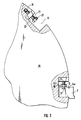
- FIG. 3 the manner of attachment of the basic holder or the associated base part 2 in the receiving recess 19 of a turret 20 is one (not shown Neten) turret lathe illustrates:
- the actuating head 22 of the clamping screw 21 serves to rotate it, and when it is unscrewed from the threaded bore 24 in the side wall 23, it interferes with the clamping surface 18 next to the groove 13 with the wedge ramp surface 14a.
Landscapes
- Engineering & Computer Science (AREA)
- Mechanical Engineering (AREA)
- Cutting Tools, Boring Holders, And Turrets (AREA)
- Gripping On Spindles (AREA)
Applications Claiming Priority (2)
| Application Number | Priority Date | Filing Date | Title |
|---|---|---|---|
| DE8904239U | 1989-04-06 | ||
| DE8904239U DE8904239U1 (de) | 1989-04-06 | 1989-04-06 | Werkzeug-Grundhalter zur Befestigung in einer Aufnahme-Aussparung eines Werkzeugträgers, insbesondere Revolverkopfes |
Publications (2)
| Publication Number | Publication Date |
|---|---|
| EP0391073A2 true EP0391073A2 (fr) | 1990-10-10 |
| EP0391073A3 EP0391073A3 (fr) | 1991-01-09 |
Family
ID=6837938
Family Applications (1)
| Application Number | Title | Priority Date | Filing Date |
|---|---|---|---|
| EP19900104096 Withdrawn EP0391073A3 (fr) | 1989-04-06 | 1990-03-02 | Porte-outil pour la fixation dans une partie réceptrice d'un support d'outils, en particulier une tourelle revolver |
Country Status (4)
| Country | Link |
|---|---|
| US (1) | US5031492A (fr) |
| EP (1) | EP0391073A3 (fr) |
| JP (1) | JPH02284806A (fr) |
| DE (1) | DE8904239U1 (fr) |
Cited By (2)
| Publication number | Priority date | Publication date | Assignee | Title |
|---|---|---|---|---|
| DE102004001148B3 (de) * | 2004-01-07 | 2005-06-02 | Schweizer, Dorothea | Werkzeugaufnahmevorrichtung |
| CN104159690A (zh) * | 2012-03-06 | 2014-11-19 | 伊斯卡有限公司 | 配置用于输送经加压冷却剂的切割刀片和刀片支架 |
Families Citing this family (13)
| Publication number | Priority date | Publication date | Assignee | Title |
|---|---|---|---|---|
| DE8904239U1 (de) * | 1989-04-06 | 1989-06-29 | Zinner GmbH Präzisionswerkzeuge, 8500 Nürnberg | Werkzeug-Grundhalter zur Befestigung in einer Aufnahme-Aussparung eines Werkzeugträgers, insbesondere Revolverkopfes |
| DE10113707C1 (de) * | 2001-03-16 | 2002-10-10 | Mapal Fab Praezision | Werkzeug zur spanabtragenden Bearbeitung eines Werkstücks aus hochfestem Material |
| US6568303B1 (en) * | 2002-04-23 | 2003-05-27 | Richard Bentley | Method and apparatus for cutting rings from ring forgings |
| WO2005037499A2 (fr) * | 2003-10-14 | 2005-04-28 | Manchester Tool Company | Machine de coupe de metal |
| SE528614C2 (sv) * | 2005-05-02 | 2006-12-27 | Sandvik Intellectual Property | Avstickningsblad för svarvningsändamål innefattande en tillsatsdel |
| DE102005024746A1 (de) * | 2005-05-31 | 2006-12-07 | Hartmetall-Werkzeugfabrik Paul Horn Gmbh | Werkzeughaltersystem |
| IL195696A0 (en) * | 2008-12-03 | 2009-09-01 | Iscar Ltd | Tool holder for clamping an insert holder |
| IL205988A (en) * | 2010-05-26 | 2015-03-31 | Iscar Ltd | Assembling a tool and holding a tool for it |
| US9259788B2 (en) | 2012-03-06 | 2016-02-16 | Iscar, Ltd. | Parting blade and blade holder configured for conveyance of pressurized coolant |
| EP2745963B2 (fr) | 2012-12-19 | 2021-03-17 | Seco Tools Ab | Accouplement pour un système de refroidissement dans un outil de coupe |
| US10455881B2 (en) * | 2015-04-21 | 2019-10-29 | Cadequip, Inc. | Adjustable headgear mount system |
| US10299528B2 (en) * | 2015-04-21 | 2019-05-28 | Cadequip, Inc. | Adjustable headgear mount system |
| EP3357612B1 (fr) * | 2017-02-03 | 2022-11-02 | Sandvik Intellectual Property AB | Procédé d'unisage d'une rainure |
Family Cites Families (12)
| Publication number | Priority date | Publication date | Assignee | Title |
|---|---|---|---|---|
| GB759147A (en) * | 1953-03-30 | 1956-10-17 | Victor John Page | Improvements relating to tool-holders for lathes and like machines |
| FR1187987A (fr) * | 1957-11-16 | 1959-09-17 | Porte-outil à serrages combinés de l'outil | |
| US3136030A (en) * | 1963-03-20 | 1964-06-09 | William R Jarrett | Tool holder |
| US3436799A (en) * | 1966-09-06 | 1969-04-08 | Posa Cut Corp | Cutting tool |
| US3497935A (en) * | 1967-02-15 | 1970-03-03 | C & L Machine Shop Inc | Cut-off tool assembly |
| FR2187478B1 (fr) * | 1972-06-10 | 1976-09-17 | Sandvik Ab | |
| FR2300645A1 (fr) * | 1975-02-17 | 1976-09-10 | Wolfor Modern Outillage | Perfectionnements aux porte-lames utilises sur des tours paralleles |
| US4082020A (en) * | 1977-01-21 | 1978-04-04 | United States Steel Corporation | Tool-clamping device and method of setting up a pipe cutoff machine |
| US4332513A (en) * | 1980-07-24 | 1982-06-01 | General Electric Company | Face grooving tool |
| DE8126791U1 (de) * | 1981-09-14 | 1983-03-17 | Iscar Hartmetall GmbH, 7505 Ettlingen | Abstechwerkzeug mit auswechselbaren schneidkoerpern und kuehlsystem |
| US4658875A (en) * | 1986-03-24 | 1987-04-21 | Bosko Grabovac | Knife holder |
| DE8904239U1 (de) * | 1989-04-06 | 1989-06-29 | Zinner GmbH Präzisionswerkzeuge, 8500 Nürnberg | Werkzeug-Grundhalter zur Befestigung in einer Aufnahme-Aussparung eines Werkzeugträgers, insbesondere Revolverkopfes |
-
1989
- 1989-04-06 DE DE8904239U patent/DE8904239U1/de not_active Expired
-
1990
- 1990-02-26 US US07/485,200 patent/US5031492A/en not_active Expired - Fee Related
- 1990-03-02 EP EP19900104096 patent/EP0391073A3/fr not_active Withdrawn
- 1990-04-04 JP JP2091317A patent/JPH02284806A/ja active Pending
Cited By (2)
| Publication number | Priority date | Publication date | Assignee | Title |
|---|---|---|---|---|
| DE102004001148B3 (de) * | 2004-01-07 | 2005-06-02 | Schweizer, Dorothea | Werkzeugaufnahmevorrichtung |
| CN104159690A (zh) * | 2012-03-06 | 2014-11-19 | 伊斯卡有限公司 | 配置用于输送经加压冷却剂的切割刀片和刀片支架 |
Also Published As
| Publication number | Publication date |
|---|---|
| EP0391073A3 (fr) | 1991-01-09 |
| JPH02284806A (ja) | 1990-11-22 |
| US5031492A (en) | 1991-07-16 |
| DE8904239U1 (de) | 1989-06-29 |
Similar Documents
| Publication | Publication Date | Title |
|---|---|---|
| EP0784524B1 (fr) | Foret a pointe rapportee | |
| DE69213188T2 (de) | Fräser | |
| EP0118806B1 (fr) | Outil de forage avec élément de coupe interchangeable | |
| EP0391073A2 (fr) | Porte-outil pour la fixation dans une partie réceptrice d'un support d'outils, en particulier une tourelle revolver | |
| EP0126432A1 (fr) | Outil de fraisage | |
| DE1110956B (de) | Halterung fuer Muttern | |
| WO2002014003A1 (fr) | Plaque de coupe pour outils rotatifs | |
| DE4339537A1 (de) | Klemmhalter für Schneidplatten | |
| EP0259846A1 (fr) | Outil de coupe pour l'usinage de métal par enlèvement de copeaux comme le tronçonnage, le chanfreinage, le planage et le fraisage | |
| DE2736612C3 (de) | Wendeplatten-Messerkopf | |
| DE102008063127A1 (de) | Werkzeug mit einem lösbar gespannten Schneidkörper | |
| DE3013876A1 (de) | Spanabhebendes werkzeug | |
| DE1809616C3 (de) | Verstellbares Möbelscharnier Zusätzen: 21 Ol 082 | |
| EP0319748A1 (fr) | Foret de precision | |
| DE2911358A1 (de) | Senker | |
| DE2452019C3 (de) | Fräswerkzeug mit Schneidplatte | |
| DE2245139A1 (de) | Ausdrehkopf | |
| DE2921670A1 (de) | Vorrichtung zum bohren, fraesen und profilieren von holz, kunststoff u.ae. werkstoffen | |
| EP0356575A2 (fr) | Dispositif de serrage pour tour | |
| DE3105181A1 (de) | Schneidwerkzeug | |
| DE2609617B2 (de) | Bohrstange, insbesondere für die Metallbearbeitung | |
| DE3026513A1 (de) | Aufbohrwerkzeug, insbes. plansenker | |
| DE3619153A1 (de) | Greiferzange | |
| DE1958574A1 (de) | Vorrichtung zum Einspannen von Wendeschneidplatten | |
| EP0038368B1 (fr) | Dispositif de serrage par coulissement |
Legal Events
| Date | Code | Title | Description |
|---|---|---|---|
| PUAI | Public reference made under article 153(3) epc to a published international application that has entered the european phase |
Free format text: ORIGINAL CODE: 0009012 |
|
| AK | Designated contracting states |
Kind code of ref document: A2 Designated state(s): DE ES FR GB IT |
|
| PUAL | Search report despatched |
Free format text: ORIGINAL CODE: 0009013 |
|
| AK | Designated contracting states |
Kind code of ref document: A3 Designated state(s): DE ES FR GB IT |
|
| STAA | Information on the status of an ep patent application or granted ep patent |
Free format text: STATUS: THE APPLICATION IS DEEMED TO BE WITHDRAWN |
|
| 18D | Application deemed to be withdrawn |
Effective date: 19910710 |