EP0391079A2 - Procédé pour entreposer (stocker) des coupes d'emballage et pour alimenter la plieuse d'une machine d'emballage avec celles-ci - Google Patents
Procédé pour entreposer (stocker) des coupes d'emballage et pour alimenter la plieuse d'une machine d'emballage avec celles-ci Download PDFInfo
- Publication number
- EP0391079A2 EP0391079A2 EP90104252A EP90104252A EP0391079A2 EP 0391079 A2 EP0391079 A2 EP 0391079A2 EP 90104252 A EP90104252 A EP 90104252A EP 90104252 A EP90104252 A EP 90104252A EP 0391079 A2 EP0391079 A2 EP 0391079A2
- Authority
- EP
- European Patent Office
- Prior art keywords
- stack
- stacks
- material web
- blanks
- conveyor
- Prior art date
- Legal status (The legal status is an assumption and is not a legal conclusion. Google has not performed a legal analysis and makes no representation as to the accuracy of the status listed.)
- Granted
Links
Images



Classifications
-
- B—PERFORMING OPERATIONS; TRANSPORTING
- B65—CONVEYING; PACKING; STORING; HANDLING THIN OR FILAMENTARY MATERIAL
- B65H—HANDLING THIN OR FILAMENTARY MATERIAL, e.g. SHEETS, WEBS, CABLES
- B65H1/00—Supports or magazines for piles from which articles are to be separated
- B65H1/30—Supports or magazines for piles from which articles are to be separated with means for replenishing the pile during continuous separation of articles therefrom
-
- B—PERFORMING OPERATIONS; TRANSPORTING
- B65—CONVEYING; PACKING; STORING; HANDLING THIN OR FILAMENTARY MATERIAL
- B65B—MACHINES, APPARATUS OR DEVICES FOR, OR METHODS OF, PACKAGING ARTICLES OR MATERIALS; UNPACKING
- B65B19/00—Packaging rod-shaped or tubular articles susceptible to damage by abrasion or pressure, e.g. cigarettes, cigars, macaroni, spaghetti, drinking straws or welding electrodes
- B65B19/02—Packaging cigarettes
- B65B19/22—Wrapping the cigarettes; Packaging the cigarettes in containers formed by folding wrapping material around formers
- B65B19/228—Preparing and feeding blanks
-
- B—PERFORMING OPERATIONS; TRANSPORTING
- B65—CONVEYING; PACKING; STORING; HANDLING THIN OR FILAMENTARY MATERIAL
- B65H—HANDLING THIN OR FILAMENTARY MATERIAL, e.g. SHEETS, WEBS, CABLES
- B65H2701/00—Handled material; Storage means
- B65H2701/10—Handled articles or webs
- B65H2701/11—Dimensional aspect of article or web
- B65H2701/112—Section geometry
- B65H2701/1123—Folded article or web
- B65H2701/11231—Fan-folded material or zig-zag or leporello
Definitions
- the invention relates to a method for storing (storing) blanks and feeding them to a folding unit of a packaging machine, in particular blanks for producing hinged boxes (hinge-lid packs) for cigarettes, the blanks forming a continuous material web with one another are connected and separated from them for processing. Furthermore, the invention relates to a device for applying the method.
- blanks consisting of (thin) cardboard can also be made available to the packaging machine in the form of a continuous material web.
- the blanks are preformed within the material web by punching and embossing, but are connected to one another via residual connections or thin webs to form the material web.
- the remaining connections are arranged in this known proposal in the area of those parts of the blanks that remain hidden in the finished package (DE-A-37 16 897).
- the invention is concerned with the sensible storage or storage of (pack) blanks which are connected to one another in the sense of the above prior art to form a continuous web of material.
- the object on which the invention is based is to store or store the material web in such a way that it can be made available to the packaging machine or the packaging members thereof in a particularly efficient manner.
- the method according to the invention is characterized in that the material web is stacked in a zigzag-shaped fold, opposing folds being formed in the area of connections between adjacent blanks, and in that the zigzag-shaped material web for Making the individual blanks off and off in a stretched one Shape is drawn.
- the arrangement of the material web in the stack under an accordion-like arrangement results in a particularly high storage capacity since the cuboid stacks can be arranged in a space-saving manner.
- the processing of the material web within the packaging machine is also easy to accomplish by pulling the material web from the stacks and shaping it back into the stretched position.
- a continuous, continuous material web is placed in several contiguous stacks, the stacks being interconnected by stretched web sections of the material web.
- a stock of blanks consisting of several stacks can be processed in connection and without interruption.
- the bottom or last blank of a stack is connected to the first or top blank of a subsequent stack via an upright, stretched web section.
- the upright path section extends between two immediately and closely adjacent stacks as a separating element.
- the stacks formed from the material web are made available in groups in several and successively fed to a stationary removal station in or on the packaging machine.
- the stacks are dismantled one after the other to form the continuous material web.
- the removal station can be designed to be stationary, the stacks being conveyed to the removal station one after the other.
- a take-off device for the material web can gradually move from one stack to the next in the removal station.
- Another proposal of the invention is to store several groups of stacks, each arranged in a row, on a base (pallet) and one after the other to be handed over from this document to a conveyor assigned to the packaging machine.
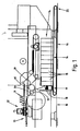
- the details shown in the drawings relate to the supply of a packaging machine 10 with blanks 11 made of (thin) cardboard for the production of (cigarette) packs of the hinged-box type (hinge-lid pack).
- the blanks 11 enter a cutting station 12 of the packaging machine 10 and here by downward movement in pockets of a plate-like folding turret 13 which is rotatable about a vertical axis.
- the packaging machine 10 has a larger supply of blanks 14, namely a plurality of stacks 15 arranged closely next to one another from blanks 11 arranged one above the other successively fed to a fixed removal station 17.
- the stack 15 lying at the front in the conveying direction is continuously dismantled.
- the position of the stack 15 in the removal station 17 is determined by a fixed stop, namely by an upright stop wall 18.
- the stacks 15 are formed from continuous material webs 19, which in turn consist of a plurality of blanks 11 connected to one another at the longitudinal edges. In the area of the cutting station 12, the cuts 11 are separated from the material web 19 and processed individually.
- the material web 19 is folded in a zigzag shape to form the stacks 15.
- Opposing fold edges 20 are formed on the edges of the blanks 11, respectively.
- the material web 19 is here essentially designed as shown and described in DE-A-37 16 897. Cuts 11 for the production of hinged boxes (hinge-lid packs) can be torn off at the longitudinal edges or shearable residual connections 21 connected to one another. Compared to the embodiment of DE-A-37 16 897, according to FIG. 7, the blanks 11 are provided with an integrally connected collar. In this respect, the blanks correspond to the embodiment in EP-B-6 872.
- the stacks 15 formed from the folded material web 19 are dissolved in the removal station 17 in that the material web 19 drawn off at the top of a stack is brought back to the stretched position.
- a plurality of stacks 15 arranged side by side, namely a group 22, are formed from a continuous, uninterrupted material web 19.
- the web section 23 is arranged in an upright plane, namely as a separating element between the closely adjacent stacks 15 (FIG. 6).
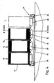
- the entire group 22 from z. B. seven stacks 15 (Fig. 3) can be broken down without manual intervention one after the other as a continuous material web.
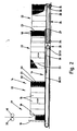
- a movable support frame namely a pallet 24 which is designed in a special way. In the present exemplary embodiment (FIGS. 3 and 4), this is suitable for accommodating four groups 22 of connected stacks 15.
- the pallet 24 is in front of a loading end 25 of the stack conveyor 16 movable transversely to this, such that a group 22 stack 15 arranged next to one another is always aligned with the stack conveyor 16.
- a further group 22 is transferred to the stack conveyor 16 after the pallet 24 has been moved laterally.
- a group 22 is transferred automatically from the pallet 24 to the stacking conveyor 16.
- a group 22 of stacks 15 on the pallet 24 is grasped on the underside by a lifting conveyor 26, lifted from the pallet 24, moved in the longitudinal direction and placed on the stack conveyor 16.
- the lifting conveyor 26 is designed as an elongated support arm with a stop elevation 27 at the free end. The lifting conveyor 26 can be moved back and forth in the longitudinal direction of the stacking conveyor 16 up to a group 22, the stop elevation 27 laterally engaging a stack 15 on the edge.
- the pallet 24 is designed in a special manner for the above conveying movement of the lifting conveyor 26.
- a base plate 28 of the pallet 24 is provided with recesses 29 on the top. These channel-like recesses 29 each extend in the longitudinal direction of a group 22 below the same, the width of the recess 29 being significantly less than the length of a stack 15 and thus as the length of a blank 11.
- the stack 15 can have edge or end regions rest on the base plate 28. In the central area, the stack 15 is exposed, so that the lifting conveyor 26 can be moved below the stack 15 to capture a group 22.
- the stacking conveyor 16 is adapted to the operation of the lifting conveyor 26, namely consists of two sides Chen, arranged at a distance from each other belt conveyors 30, 31.
- the stacks 15 lie on these with lateral or end regions.
- the two material conveyors 30, 31 run over non-interconnected deflection rollers 32, 33, between which there remains a distance for the conveying movement of the lifting conveyor 26.
- the pallet 24 is provided on the underside with rollers 34, 35. With the help of the same, the exact relative position of the pallet 24 to the stacking conveyor 16 can be determined by at least one pair of the rollers 34, 35 entering recesses 36 of a running surface for the pallet 24.
- the individual groups 22 on the pallet 24 are separated from one another by partitions 37. These are removably arranged on the pallets 24 for the return transport of the same to the place of manufacture of the blanks 11 or the material web 19.
- the partition walls 37 consist here of corrugated cardboard.
- FIG. 6 shows an alternative with respect to the design of the removal station 17.
- the removal of the material web 19 and thus the dismantling of the stack 15 is not stationary here. Rather, a puller 38 for the material web 19 is slidably arranged above the stack 15. The puller 38 is moved from stack to stack in accordance with the dismantling of the stacks 15. While the material web 19 is being pulled off, the pulling member 38 is located centrally above the stack 15 to be removed.
- the pulling-off element 38 consists of a pair of pulling rollers 39, 40.
- the material web 19 is pulled off the stack 15 by stretching them.
- the (driven) pull rollers 39, 40 are arranged on a carriage 41 which is displaceable above the row or group 22 of the stacks 15.
- two guide rods 42 are moved.
- a traction element namely a traction cable 43, is arranged on the carriage 41 for carrying out the actuating movement.
- the pull cable 43 is actuated in cycles by a suitable drive element.
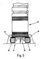
- FIGS. 7 and 8 Another special feature is shown in FIGS. 7 and 8 in detail. It is primarily about the connection to one another, that is to say the connection of successive groups 22 of stacks 15.
- an adhesive element namely an adhesive strip
- This adhesive strip 44 is arranged on the outer, free edge of the last blank 11 of the material web 19 or the upright web section 23 44.
- This adhesive strip 44 provided on one side with an adhesive layer is applied in a central region of the (last) blank 11, namely on an inner side tab 45.
- the adhesive strip 44 is arranged to form a free projection on the edge of the side tab 45, namely on the from the subsequent stack 15 remote side.
- the part of the adhesive strip 44 projecting upward beyond the blank 11 is folded over for connection to the upper, horizontally lying blank 11 of a subsequent stack 15 and is thus glued onto the top of the blank - likewise in the region of the side tab 45.
- the connection between the material webs is thus established and a continuous dismantling of an uninterrupted material web is guaranteed.
- holding means which fix the relevant exposed web section 23 to the side surface of the assigned stack 15.
- double-sided adhesive connecting strips 46 are arranged in the region of the connection point between adjacent blanks 11 on the web section 23 on the side facing the stack 15 net. These are on the one hand adhesively connected to the web section 23 and on the other hand also adhesively connected to the folded edges of the stack 15. The upright path section 23 is thus releasably fixed in position.
Landscapes
- Engineering & Computer Science (AREA)
- Mechanical Engineering (AREA)
- Making Paper Articles (AREA)
- Folding Of Thin Sheet-Like Materials, Special Discharging Devices, And Others (AREA)
- Feeding Of Articles By Means Other Than Belts Or Rollers (AREA)
- Wrapping Of Specific Fragile Articles (AREA)
- Supplying Of Containers To The Packaging Station (AREA)
Applications Claiming Priority (2)
| Application Number | Priority Date | Filing Date | Title |
|---|---|---|---|
| DE3910987A DE3910987A1 (de) | 1989-04-05 | 1989-04-05 | Verfahren und vorrichtung zum lagern (speichern) von (packungs-)zuschnitten und zufuehren derselben zu einem faltaggregat einer verpackungsmaschine |
| DE3910987 | 1989-04-05 |
Publications (3)
| Publication Number | Publication Date |
|---|---|
| EP0391079A2 true EP0391079A2 (fr) | 1990-10-10 |
| EP0391079A3 EP0391079A3 (fr) | 1991-07-31 |
| EP0391079B1 EP0391079B1 (fr) | 1994-09-28 |
Family
ID=6377900
Family Applications (1)
| Application Number | Title | Priority Date | Filing Date |
|---|---|---|---|
| EP90104252A Expired - Lifetime EP0391079B1 (fr) | 1989-04-05 | 1990-03-06 | Procédé pour entreposer (stocker) des coupes d'emballage et pour alimenter la plieuse d'une machine d'emballage avec celles-ci |
Country Status (6)
| Country | Link |
|---|---|
| US (1) | US5052995A (fr) |
| EP (1) | EP0391079B1 (fr) |
| JP (1) | JP2662074B2 (fr) |
| BR (1) | BR9001567A (fr) |
| CA (1) | CA2012968A1 (fr) |
| DE (2) | DE3910987A1 (fr) |
Cited By (1)
| Publication number | Priority date | Publication date | Assignee | Title |
|---|---|---|---|---|
| EP0885809A1 (fr) * | 1997-06-20 | 1998-12-23 | Focke & Co. (GmbH & Co.) | Procédé et dispositif de fabrication de boítes à charnière |
Families Citing this family (12)
| Publication number | Priority date | Publication date | Assignee | Title |
|---|---|---|---|---|
| DE4420396C2 (de) * | 1994-06-08 | 1998-12-10 | Id Faltex Gmbh Verpackungstech | Faltteilträger |
| US6729471B2 (en) | 1997-06-16 | 2004-05-04 | Bki Holding Corporation | Packaging a strip of material with compression to reduce volume |
| US6336307B1 (en) | 1997-10-09 | 2002-01-08 | Eki Holding Corporation | Method of packaging a strip of material for use in cutting into sheet elements arranged end to end |
| FI110681B (fi) | 1998-01-02 | 2003-03-14 | Bki Holding Corp | Menetelmä rainan pakkaamiseksi |
| US6293075B1 (en) | 1999-03-08 | 2001-09-25 | Bki Holding Corporation | Packaging a strip of material |
| US6321512B1 (en) | 1999-03-08 | 2001-11-27 | Bki Holding Corporation | Method of packaging a strip of material |
| ATE356776T1 (de) * | 2001-03-23 | 2007-04-15 | Bki Holding Corp | Verpacken einer materialbahn mit variierender breite |
| GB2391213A (en) * | 2002-07-25 | 2004-02-04 | Buralls Of Wisbech Ltd | Strip of packaging elements joined at lines of weakness |
| SE538350C2 (en) * | 2014-09-15 | 2016-05-24 | Scan Coin Ab | Distribution of coins in bags |
| JP6825729B1 (ja) * | 2020-01-20 | 2021-02-03 | 王子ホールディングス株式会社 | 継合方法 |
| JP7490435B2 (ja) * | 2020-04-15 | 2024-05-27 | 株式会社Tanax | 段ボールシート送り出し装置及び蛇腹状段ボールシート積層体補充装置 |
| CN112319905A (zh) * | 2020-09-28 | 2021-02-05 | 张文宇 | 一种应用于瓦楞纸箱生产的瓦楞纸板捆绑方法 |
Family Cites Families (12)
| Publication number | Priority date | Publication date | Assignee | Title |
|---|---|---|---|---|
| DE95784C (fr) * | ||||
| ES194765Y (es) * | 1969-12-08 | 1975-06-01 | Sengewald | Un dispositivo para la entrega de bolsas de transporte de articulos. |
| DD95784A1 (fr) * | 1972-03-27 | 1973-02-12 | ||
| DE2329267A1 (de) * | 1973-06-08 | 1975-01-02 | Dieffenbacher Gmbh Maschf | Verfahren und vorrichtung zum zusammenlegen von folien und traegerplatten zu einer presseinheit |
| US3907273A (en) * | 1974-01-28 | 1975-09-23 | Multifold Int | Machine for feeding stacked articles |
| DE2534917A1 (de) * | 1975-08-05 | 1977-02-24 | Bosch & Co Papier Und Folienwe | Verfahren zum fortlaufenden zufuehren eines papierstreifens o.dgl. in eine einwickelmaschine |
| JPS555828A (en) * | 1978-06-28 | 1980-01-17 | Minami Seiki Kk | Method of making pasted continuous slip paper |
| US4260310A (en) * | 1979-07-11 | 1981-04-07 | American Can Company | Strip feed elevator |
| JPS5812186B2 (ja) * | 1979-07-30 | 1983-03-07 | 日本電信電話株式会社 | プリンタ装置 |
| JPS6077045A (ja) * | 1983-10-03 | 1985-05-01 | Kawanoe Zoki Kk | 折りたたんだ集積物の定量取出し方法及び装置 |
| DE3627868A1 (de) * | 1986-08-16 | 1988-02-18 | Focke & Co | Vorrichtung zum zufuehren von zuschnitten zu einer verpackungsmaschine |
| DE3716897C2 (de) * | 1987-05-20 | 2001-11-22 | Focke & Co | Zuschnitte für Klappschachteln als fortlaufende Materialbahn |
-
1989
- 1989-04-05 DE DE3910987A patent/DE3910987A1/de not_active Withdrawn
-
1990
- 1990-03-06 EP EP90104252A patent/EP0391079B1/fr not_active Expired - Lifetime
- 1990-03-06 DE DE59007298T patent/DE59007298D1/de not_active Expired - Fee Related
- 1990-03-23 CA CA002012968A patent/CA2012968A1/fr not_active Abandoned
- 1990-03-28 US US07/501,827 patent/US5052995A/en not_active Expired - Fee Related
- 1990-04-04 BR BR909001567A patent/BR9001567A/pt not_active IP Right Cessation
- 1990-04-05 JP JP2089266A patent/JP2662074B2/ja not_active Expired - Lifetime
Cited By (2)
| Publication number | Priority date | Publication date | Assignee | Title |
|---|---|---|---|---|
| EP0885809A1 (fr) * | 1997-06-20 | 1998-12-23 | Focke & Co. (GmbH & Co.) | Procédé et dispositif de fabrication de boítes à charnière |
| US6206815B1 (en) | 1997-06-20 | 2001-03-27 | Focke & Co. (Gmbh & Co.) | Method and device for manufacturing hinge-lid packets |
Also Published As
| Publication number | Publication date |
|---|---|
| DE3910987A1 (de) | 1990-10-18 |
| DE59007298D1 (de) | 1994-11-03 |
| EP0391079B1 (fr) | 1994-09-28 |
| EP0391079A3 (fr) | 1991-07-31 |
| CA2012968A1 (fr) | 1990-10-05 |
| US5052995A (en) | 1991-10-01 |
| JP2662074B2 (ja) | 1997-10-08 |
| BR9001567A (pt) | 1991-04-30 |
| JPH0332826A (ja) | 1991-02-13 |
Similar Documents
| Publication | Publication Date | Title |
|---|---|---|
| DE69604380T2 (de) | Verpackungsvorrichtung für aufgestapelte papiererzeugnisse | |
| EP0258597A2 (fr) | Dispositif pour alimenter en ébauches une machine d'emballage | |
| EP0421148A2 (fr) | Dispositif et procédé pour transporter et empiler des pièces découpées pour la production des paquets de cigarettes | |
| DE4210812A1 (de) | Kartoniereinrichtung | |
| DE4210813A1 (de) | Kartoniereinrichtung | |
| EP0391079B1 (fr) | Procédé pour entreposer (stocker) des coupes d'emballage et pour alimenter la plieuse d'une machine d'emballage avec celles-ci | |
| EP0653354B1 (fr) | Emballage pour livres et/ou autres objets; procédé et dispositif pour sa fabrication | |
| EP0957055A2 (fr) | Dispositif d'empilage | |
| DE3718081A1 (de) | Vorrichtung zum bilden eines stapels aus einer vorgefalteten endlosbahn | |
| DE3704663C2 (de) | Vorrichtung zum Stapeln von aus Kunststoffolien hergestellten Beuteln mit Bodennaht | |
| DE3910986A1 (de) | Verfahren und vorrichtung zum herstellen von (zigaretten -) packungen | |
| EP1026081A2 (fr) | Procédé et installation d'approvisionnement de flans en carton | |
| EP0174591A2 (fr) | Dispositif pour fabriquer des emballages, en particulier cartouches de cigarettes | |
| EP0879763B1 (fr) | Arrangement de sachets d'échantillon plats d'alimentation à un traitement postérieur | |
| DE2435311A1 (de) | Verfahren und vorrichtung zur bildung von verpackungskartons | |
| DE4035350C2 (de) | Vorrichtung zur Herstellung von Schachteln | |
| DE3639982A1 (de) | Maschine zur verpackung von gegenstaenden in gruppen | |
| DE2636320C2 (de) | Vorrichtung zum automatischen Palettieren von Gegenständen, insbesondere Flaschen | |
| DE19736730A1 (de) | Gebindepackung für Zigaretten sowie Verfahren und Vorrichtung zum Herstellen derselben | |
| EP0149146B1 (fr) | Procédé d'emballage de groupes d'objets dans une boîte pliante ainsi que dispositif pour la mise en oeuvre du procédé | |
| DE4220026A1 (de) | Verfahren und Vorrichtung zum Abräumen von Zuschnittstapeln von einer Palette oder dergleichen | |
| EP0328875A2 (fr) | Procédé et dispositif de séparation d'articles plans | |
| DE1043927B (de) | Verfahren und Vorrichtung zum Verpacken von Gruppen von stehenden Gegenstaenden, z. B. Buechsen, in an beiden Stirnseiten offene Huellen aus Pappe od. dgl. | |
| DE202019103071U1 (de) | Palettiervorrichtung | |
| DE2246769C3 (de) | Vorrichtung zum Entnehmen und Aufrichten von in einem Stapel flach zusammengelegten Kartonhülsen |
Legal Events
| Date | Code | Title | Description |
|---|---|---|---|
| PUAI | Public reference made under article 153(3) epc to a published international application that has entered the european phase |
Free format text: ORIGINAL CODE: 0009012 |
|
| AK | Designated contracting states |
Kind code of ref document: A2 Designated state(s): DE FR GB IT |
|
| PUAL | Search report despatched |
Free format text: ORIGINAL CODE: 0009013 |
|
| AK | Designated contracting states |
Kind code of ref document: A3 Designated state(s): DE FR GB IT |
|
| 17P | Request for examination filed |
Effective date: 19920125 |
|
| 17Q | First examination report despatched |
Effective date: 19930517 |
|
| GRAA | (expected) grant |
Free format text: ORIGINAL CODE: 0009210 |
|
| AK | Designated contracting states |
Kind code of ref document: B1 Designated state(s): DE FR GB IT |
|
| REF | Corresponds to: |
Ref document number: 59007298 Country of ref document: DE Date of ref document: 19941103 |
|
| GBT | Gb: translation of ep patent filed (gb section 77(6)(a)/1977) |
Effective date: 19941011 |
|
| ITF | It: translation for a ep patent filed | ||
| ET | Fr: translation filed | ||
| PLBE | No opposition filed within time limit |
Free format text: ORIGINAL CODE: 0009261 |
|
| STAA | Information on the status of an ep patent application or granted ep patent |
Free format text: STATUS: NO OPPOSITION FILED WITHIN TIME LIMIT |
|
| 26N | No opposition filed | ||
| PGFP | Annual fee paid to national office [announced via postgrant information from national office to epo] |
Ref country code: FR Payment date: 20010313 Year of fee payment: 12 |
|
| REG | Reference to a national code |
Ref country code: GB Ref legal event code: IF02 |
|
| PG25 | Lapsed in a contracting state [announced via postgrant information from national office to epo] |
Ref country code: FR Free format text: LAPSE BECAUSE OF NON-PAYMENT OF DUE FEES Effective date: 20021129 |
|
| REG | Reference to a national code |
Ref country code: FR Ref legal event code: ST |
|
| PGFP | Annual fee paid to national office [announced via postgrant information from national office to epo] |
Ref country code: GB Payment date: 20030305 Year of fee payment: 14 |
|
| PGFP | Annual fee paid to national office [announced via postgrant information from national office to epo] |
Ref country code: DE Payment date: 20030308 Year of fee payment: 14 |
|
| PG25 | Lapsed in a contracting state [announced via postgrant information from national office to epo] |
Ref country code: GB Free format text: LAPSE BECAUSE OF NON-PAYMENT OF DUE FEES Effective date: 20040306 |
|
| PG25 | Lapsed in a contracting state [announced via postgrant information from national office to epo] |
Ref country code: DE Free format text: LAPSE BECAUSE OF NON-PAYMENT OF DUE FEES Effective date: 20041001 |
|
| GBPC | Gb: european patent ceased through non-payment of renewal fee | ||
| PG25 | Lapsed in a contracting state [announced via postgrant information from national office to epo] |
Ref country code: IT Free format text: LAPSE BECAUSE OF NON-PAYMENT OF DUE FEES;WARNING: LAPSES OF ITALIAN PATENTS WITH EFFECTIVE DATE BEFORE 2007 MAY HAVE OCCURRED AT ANY TIME BEFORE 2007. THE CORRECT EFFECTIVE DATE MAY BE DIFFERENT FROM THE ONE RECORDED. Effective date: 20050306 |