EP0391265A2 - Procédé et appareil d'ombrage à densité linéaire variable pour un écran de cadre graphique - Google Patents
Procédé et appareil d'ombrage à densité linéaire variable pour un écran de cadre graphique Download PDFInfo
- Publication number
- EP0391265A2 EP0391265A2 EP90106095A EP90106095A EP0391265A2 EP 0391265 A2 EP0391265 A2 EP 0391265A2 EP 90106095 A EP90106095 A EP 90106095A EP 90106095 A EP90106095 A EP 90106095A EP 0391265 A2 EP0391265 A2 EP 0391265A2
- Authority
- EP
- European Patent Office
- Prior art keywords
- pixels
- pixel
- polygon
- triangle
- triangles
- Prior art date
- Legal status (The legal status is an assumption and is not a legal conclusion. Google has not performed a legal analysis and makes no representation as to the accuracy of the status listed.)
- Granted
Links
Images


Classifications
-
- G—PHYSICS
- G06—COMPUTING OR CALCULATING; COUNTING
- G06T—IMAGE DATA PROCESSING OR GENERATION, IN GENERAL
- G06T15/00—Three-dimensional [3D] image rendering
- G06T15/50—Lighting effects
- G06T15/80—Shading
Definitions
- the present invention pertains to a method and apparatus for linear shading in a raster graphics display according to the preamble of the independent claims.
- a raster graphics system an image is created by an array of points, known as pixels, illuminated to different intensities. In a monochrome system, this intensity is known as luminance. In a color graphics system, there are separate luminances for red, green, and blue. Thus, a color graphics system can be considered to be three monochrome graphics systems operating in parallel.
- objects in such a system are modeled as a series of polygons, where each vertex of the polygon may be at a different luminance.
- the points on the interior of the polygon will have luminance values interpolated from the luminance values at the vertices.
- the luminance for each pixel has been calculated individually by computing the distance from each pixel to each of the vertices of the polygon and doing a linear interpolation. This type of linear shading is commonly known as "Gouraud" shading. Because of the extreme computational load, this process is very slow.
- a method and apparatus for linear shading of a polygon rendered in a raster graphics display is disclosed.
- Means is included for selecting a key vertex which is located opposite to an edge of the polygon having a selected orientation.
- Means is further included for dividing the polygon into a group of triangles so as to create a base leg for each of the triangles in the selected orientation.
- Means is further included for calculating the horizontal endpoints and their associated luminance values for each scan line between each triangle's base and the base's opposite vertex so as to describe a plurality of scan lines further comprising a plurality of pixels within each triangle.
- Means for interpolating the luminance of each of the scan line pixels so as to shade each of the triangles completes the linear shading.
- the luminance value for several pixels can be calculated simultaneously.
- the method of the invention also lends itself to an efficient implementation in a custom integrated circuit chip set.
- the polygon 10 is first broken down into triangles 12 as shown in Figure 3. This process must be done in such a way that one leg of each resulting triangle is in a particular selected orientation. This leg shall be known as the base.
- the selected orientation should be chosen so that the object to be drawn has a large number of lines to be drawn in the selected orientation, since this method is optimized for rapid drawing in the selected orientation. For example, most natural objects contain many horizontal lines, so it is typically advantageous to choose the selected orientation to be horizontal. If this invention is embodied in a system using a single-buffered image memory, the memory design may constrain the choice of orientation. For ease in describing the invention herein, the selected orientation shall be designated as horizontal, although the invention is not limited to this orientation.
- each vertex has X and Y coordinates in a raster graphics system. These coordinates are integers which are assigned to each pixel location on the display screen. Two points are on the same horizontal line if they have the same Y coordinate. For example, points V5 and V6 of Figure 4 have the same Y coordinate YA. To find the coordinates of point V9 for example, note that the Y coordinate of point V9 is the same as the Y coordinate of point V8. Thus, all that is necessary to locate the base for triangle V7-V8-V9 is to find the point on line V1-V7 that has the same Y coordinate as point V8.
- An N-sided polygon can be decomposed into no more than N+2 triangles of the type useful to implement the method of the invention.
- DXL (X2-X1)/N Equation 1
- DXR (X3-X1)/N Equation 2
- DLL (L2-L1)/N Equation 3
- DLR (L3-L1)/N Equation 4
- N will be a negative number.
- DXL, DXR, DLL, and DLR may be positive or negative and will have both integer and fractional parts.
- step 8 would decrement Y rather than incrementing it.
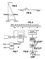
- Figure 6 represents a single horizontal line within a triangle.
- All images are really composed of discrete pixels at varying luminance levels. This is what the dots P along the line in Figure 6 represent.
- DL will contain integer and fractional parts, and may be positive or negative. Note also that DL is not the same as DLL or DLR.
- Figure 13 is a flow chart generally showing the processing steps employed by the method of the invention.
- the method starts at step 100 by selecting a key vertex which is located opposite to an edge of the polygon having a selected orientation.
- the process then proceeds to step 110 wherein the polygon is divided into a group of triangles so as to create a base for each triangle in the selected orientation.
- the method calculates the line parameters including the horizontal endpoints and luminance values for each line between each triangle's base and the base's opposite vertex so as to describe a plurality of scan lines further comprising a plurality of pixels within each triangle.
- step 130 interpolates the luminance of each scan line pixel so as to shade each of the triangles. As a result of shading all of the triangles, the entire polygon is, of course, shaded.
- MAC multiplier-accumulator
- the architecture is shown in Figure 8 and comprises a means for providing polygon descriptions 22, a graphics processor 30, a triangle engine 35 and a line engine 50.
- the graphics processor 30 takes polygon descriptions and decomposes them into triangles of the type mentioned earlier. It then calculates X1, Y1, L1, N, DXL, DXR, DLL and DLR and feeds these values to the triangle engine 35.
- the graphics processor may perform other functions as well. Notice that with a suitable buffer connecting the graphics processor to the triangle engine, the graphics processor needn't wait for the triangle engine to finish (or even start) before it begins work on the next polygon.
- the triangle engine 35 accepts the data from the graphics processor and produces a series of XL, XR, LL, and LR values which, when used by the line engine, will produce the image of a properly shaded triangle. It may advantageously consist of the four MACs mentioned earlier, an N counter, an up/down Y counter, and a hardware state machine to control the other elements. Counters can be used for N and Y because they are always either loaded, incremented by one, or decremented by one.
- the line engine 50 takes each set of XL, XR, LL, and LR values and generates a series of pixel values which will, in conjunction with all other pixel values so generated, result in the display of the polygon as desired.
- the process of displaying the pixel values is well known.
- the luminance value for any point between (XL,Y) and (XR,Y) can be generated by an accumulator.
- a counter can be used to generate the X values.
- the image memory for the display field is 1024 x 1024 pixels and is composed of memories with a cycle time of 100 nanoseconds.
- a "pixel segment” may be defined as a group of pixels to be operated on simultaneously. These pixels must be adjacent to each other and in a straight line horizontally. This is the reason for the earlier restriction of the method that the base of each triangle be horizontal.
- a pixel segment is four pixels wide. Those skilled in the art will recognize that a pixel segment can be any number of pixels wide and it is possible to orient such segments in a nonhorizontal fashion. Any horizontal line to be drawn can now be broken into a number of pixel segments 39-42, with some odd number of pixels comprising a partial segment 39, for example, on the ends of the line as shown in Figure 9.
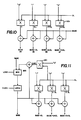
- FIG. 10 shows how the luminance values for all four pixels 84-87 in a segment can be calculated simultaneously in a multiplier-adder array. Note the similarity of this array to the block diagram of a MAC 20 as shown in Figure 7. Note further that the base value for the (K+1) pixel segment is equal to the base value of the Kth pixel segment plus 4*DL where K is any integer. Note also that since each base value always has zero added to it, the multiplier 201h and adder 204L shown in the left hand column of Figure 10 are unnecessary and have been eliminated in the embodiment shown in Figure 11.
- the initial base value and DL may be loaded while giving the multipliers 201 time to settle (since multipliers are typically the slowest part of this architecture). Thereafter new pixel segments are generated, each containing four pixels, in a single clock cycle.
- the minimum clock cycle is determined by the settling time of the adder-mux-latch loop.
- the actual clock cycle will likely be slower because the storage of the created pixel values in the image memory takes more time than the generation of a new pixel segment.
- the pixel value outputs will advantageously be latched so that the new pixel value, (the next segment) can be generated while the last segment is being written to the image memory.
- a multiplexer 200 is preferably included so that the initial base value (the luminance value of the first pixel in the first segment) can be loaded.
- This table can be extended to allow operation on any number of pixels simultaneously.
- the table may be advantageously stored in any suitable known digital memory storage device such as a RAM, ROM or equivalent device.
- the line engine of Figure 12 includes a multiplexer 200, latch 202, adders 204, multipliers 201, lookup table 210 and write enable generator 214.
- the operation of the line engine shown in Figure 12 is as described above with respect to Figure 11 with the added capabilities of inhibiting the generation of write-enable pulses to the image memory for partial pixel segments by means of write-enable generator 214, and the storage and access of multiplier values in the lookup table 210 in accordance with Table 1.
- all or part of the invention may be implemented in a custom logic device embedded in semi-conductor material. If this is done, it may be desireable to remove unused capability from the device in order to save silicon. For example, when working with four pixels per segment the largest multiplier value from Table 1 is 4. Most of the capability of a 16x16 or 24x24 multiplier would be wasted. A 3x16 or a 3x24 multiplier would be a better choice, and could be implemented as a series of shifters, multiplexers, and adders.
Landscapes
- Engineering & Computer Science (AREA)
- Computer Graphics (AREA)
- Physics & Mathematics (AREA)
- General Physics & Mathematics (AREA)
- Theoretical Computer Science (AREA)
- Image Generation (AREA)
Applications Claiming Priority (2)
| Application Number | Priority Date | Filing Date | Title |
|---|---|---|---|
| US07/332,602 US5036316A (en) | 1989-04-03 | 1989-04-03 | Method and apparatus for high speed linear shading in a raster graphics system |
| US332602 | 1989-04-03 |
Publications (3)
| Publication Number | Publication Date |
|---|---|
| EP0391265A2 true EP0391265A2 (fr) | 1990-10-10 |
| EP0391265A3 EP0391265A3 (fr) | 1991-03-13 |
| EP0391265B1 EP0391265B1 (fr) | 1994-05-11 |
Family
ID=23298964
Family Applications (1)
| Application Number | Title | Priority Date | Filing Date |
|---|---|---|---|
| EP90106095A Expired - Lifetime EP0391265B1 (fr) | 1989-04-03 | 1990-03-30 | Procédé et appareil d'ombrage à densité linéaire variable pour un écran de cadre graphique |
Country Status (5)
| Country | Link |
|---|---|
| US (1) | US5036316A (fr) |
| EP (1) | EP0391265B1 (fr) |
| JP (1) | JPH0362182A (fr) |
| CA (1) | CA2011650A1 (fr) |
| DE (1) | DE69008766T2 (fr) |
Cited By (2)
| Publication number | Priority date | Publication date | Assignee | Title |
|---|---|---|---|---|
| EP0486144A3 (en) * | 1990-11-15 | 1993-07-21 | International Business Machines Corporation | High performance triangle interpolator |
| EP0817131A3 (fr) * | 1996-06-28 | 1999-08-18 | Cirrus Logic, Inc. | Système et méthode pour affichage de polygones |
Families Citing this family (14)
| Publication number | Priority date | Publication date | Assignee | Title |
|---|---|---|---|---|
| US5343558A (en) * | 1991-02-19 | 1994-08-30 | Silicon Graphics, Inc. | Method for scan converting shaded triangular polygons |
| US5448686A (en) * | 1992-01-02 | 1995-09-05 | International Business Machines Corporation | Multi-resolution graphic representation employing at least one simplified model for interactive visualization applications |
| JP3713055B2 (ja) * | 1992-06-24 | 2005-11-02 | 日本電信電話株式会社 | 3次元lsi形状シミュレーションシステム |
| JP3416892B2 (ja) * | 1992-06-24 | 2003-06-16 | 日本電信電話株式会社 | ブールトラジェクトソリッドサーフェス移動システム |
| US5379225A (en) * | 1992-06-24 | 1995-01-03 | Intel Corporation | Method for efficient calculation of vertex movement for three-dimensional topography simulation |
| US5367465A (en) * | 1992-06-24 | 1994-11-22 | Intel Corporation | Solids surface grid generation for three-dimensional topography simulation |
| JP3416894B2 (ja) * | 1992-06-24 | 2003-06-16 | 日本電信電話株式会社 | コンピュータ制御ディスプレイシステム |
| US5631935A (en) * | 1993-05-06 | 1997-05-20 | Run-Rad Unlimited Networking, Ltd. | Method and apparatus for governing information transfer using an efficient transport protocol |
| GB2278524B (en) * | 1993-05-28 | 1997-12-10 | Nihon Unisys Ltd | Method and apparatus for rendering visual images employing area calculation and blending of fractional pixel lists for anti-aliasing and transparency |
| US5555355A (en) * | 1993-09-14 | 1996-09-10 | International Business Machines Corporation | System and method for clamping variable values without using branch instructions |
| US5463723A (en) * | 1993-09-20 | 1995-10-31 | International Business Machines Corporation | Method and apparatus for filling polygons |
| US5617524A (en) * | 1995-01-31 | 1997-04-01 | Compaq Computer Corporation | Run slice line draw engine with shading capabilities |
| US6477143B1 (en) | 1998-01-25 | 2002-11-05 | Dror Ginossar | Method and apparatus for packet network congestion avoidance and control |
| US10621763B2 (en) | 2016-07-28 | 2020-04-14 | Microsoft Technology Licensing, Llc. | Sketch-effect hatching |
Family Cites Families (9)
| Publication number | Priority date | Publication date | Assignee | Title |
|---|---|---|---|---|
| US4827445A (en) * | 1982-02-18 | 1989-05-02 | University Of North Carolina | Image buffer having logic-enhanced pixel memory cells and method for setting values therein |
| JPS6079475A (ja) * | 1983-10-07 | 1985-05-07 | Fujitsu Ltd | 図形処理装置 |
| US4658247A (en) * | 1984-07-30 | 1987-04-14 | Cornell Research Foundation, Inc. | Pipelined, line buffered real-time color graphics display system |
| GB8500493D0 (en) * | 1985-01-09 | 1985-02-13 | Crosfield Electronics Ltd | Video retouching systems |
| DE3688918T2 (de) * | 1985-05-24 | 1993-12-23 | Hitachi Ltd | System für geometrische Verarbeitung. |
| FR2594980A1 (fr) * | 1986-02-21 | 1987-08-28 | Gen Electric | Processeur de visualisation pour un systeme de visualisation graphique |
| US4901251A (en) * | 1986-04-03 | 1990-02-13 | Advanced Micro Devices, Inc. | Apparatus and methodology for automated filling of complex polygons |
| EP0288629A1 (fr) * | 1987-04-30 | 1988-11-02 | International Business Machines Corporation | Méthode de Gouraud pour ombrer sur un appareil d'affichage graphique |
| JPH0693741B2 (ja) * | 1988-01-14 | 1994-11-16 | 大日本スクリーン製造株式会社 | 網伏せにおける画像整形方法 |
-
1989
- 1989-04-03 US US07/332,602 patent/US5036316A/en not_active Expired - Lifetime
-
1990
- 1990-03-07 CA CA002011650A patent/CA2011650A1/fr not_active Abandoned
- 1990-03-30 EP EP90106095A patent/EP0391265B1/fr not_active Expired - Lifetime
- 1990-03-30 DE DE69008766T patent/DE69008766T2/de not_active Expired - Fee Related
- 1990-04-03 JP JP2087643A patent/JPH0362182A/ja active Pending
Cited By (3)
| Publication number | Priority date | Publication date | Assignee | Title |
|---|---|---|---|---|
| EP0486144A3 (en) * | 1990-11-15 | 1993-07-21 | International Business Machines Corporation | High performance triangle interpolator |
| US5457775A (en) * | 1990-11-15 | 1995-10-10 | International Business Machines Corporation | High performance triangle interpolator |
| EP0817131A3 (fr) * | 1996-06-28 | 1999-08-18 | Cirrus Logic, Inc. | Système et méthode pour affichage de polygones |
Also Published As
| Publication number | Publication date |
|---|---|
| US5036316A (en) | 1991-07-30 |
| JPH0362182A (ja) | 1991-03-18 |
| EP0391265A3 (fr) | 1991-03-13 |
| DE69008766D1 (de) | 1994-06-16 |
| EP0391265B1 (fr) | 1994-05-11 |
| CA2011650A1 (fr) | 1990-10-03 |
| DE69008766T2 (de) | 1994-11-10 |
Similar Documents
| Publication | Publication Date | Title |
|---|---|---|
| EP0391265B1 (fr) | Procédé et appareil d'ombrage à densité linéaire variable pour un écran de cadre graphique | |
| US6518974B2 (en) | Pixel engine | |
| US6456284B1 (en) | Graphics processor, system and method for generating screen pixels in raster order utilizing a single interpolator | |
| EP0310176B1 (fr) | Méthode et appareil pour générer une image en deux dimensions | |
| JP3675488B2 (ja) | 線形補間を用いて非同次2次遠近テクスチャマッピング座標を決定する回路 | |
| US6741243B2 (en) | Method and system for reducing overflows in a computer graphics system | |
| JPH0719297B2 (ja) | グラフィック表示処理システム及び方法 | |
| WO1998029836A9 (fr) | Circuit de determination des coordonnees pour un processus de mappage de texture de perspective, du second ordre, non homogene, utilisant une interpolation lineaire | |
| US5491769A (en) | Method and apparatus for variable minification of an image | |
| US5175805A (en) | Method and apparatus for sequencing composite operations of pixels | |
| US7081903B2 (en) | Efficient movement of fragment stamp | |
| US5402533A (en) | Method and apparatus for approximating a signed value between two endpoint values in a three-dimensional image rendering device | |
| US5740344A (en) | Texture filter apparatus for computer graphics system | |
| WO2002069274A1 (fr) | Algorithme de projection de voxels par decoupage-torsion econome en memoire | |
| US5418901A (en) | Shading method and shading apparatus for computer graphics | |
| US5771046A (en) | Image processing system and method including perspective transformation of three-dimensional objects utilizing clipping plane positions | |
| US4945497A (en) | Method and apparatus for translating rectilinear information into scan line information for display by a computer system | |
| US5670981A (en) | Method for mapping a source pixel image to a destination pixel space | |
| JP2777577B2 (ja) | 図形オブジェクトのシェーディング値生成装置およびその方法 | |
| JPH11185052A (ja) | 3次元コンピュータグラフィックスのテクスチャマッピング座標計算装置および方法 | |
| Juskiw et al. | Interactive rendering of volumetric data sets | |
| US5167018A (en) | Polygon-filling apparatus | |
| US20030142107A1 (en) | Pixel engine | |
| JP2814631B2 (ja) | シェーディングにおける演算回路 | |
| JP2770514B2 (ja) | シェーディング装置 |
Legal Events
| Date | Code | Title | Description |
|---|---|---|---|
| PUAI | Public reference made under article 153(3) epc to a published international application that has entered the european phase |
Free format text: ORIGINAL CODE: 0009012 |
|
| AK | Designated contracting states |
Kind code of ref document: A2 Designated state(s): DE FR GB IT |
|
| PUAL | Search report despatched |
Free format text: ORIGINAL CODE: 0009013 |
|
| AK | Designated contracting states |
Kind code of ref document: A3 Designated state(s): DE FR GB IT |
|
| RHK1 | Main classification (correction) |
Ipc: H04N 1/46 |
|
| 17P | Request for examination filed |
Effective date: 19910812 |
|
| 17Q | First examination report despatched |
Effective date: 19931103 |
|
| GRAA | (expected) grant |
Free format text: ORIGINAL CODE: 0009210 |
|
| AK | Designated contracting states |
Kind code of ref document: B1 Designated state(s): DE FR GB IT |
|
| REF | Corresponds to: |
Ref document number: 69008766 Country of ref document: DE Date of ref document: 19940616 |
|
| ET | Fr: translation filed | ||
| ITF | It: translation for a ep patent filed | ||
| PLBE | No opposition filed within time limit |
Free format text: ORIGINAL CODE: 0009261 |
|
| STAA | Information on the status of an ep patent application or granted ep patent |
Free format text: STATUS: NO OPPOSITION FILED WITHIN TIME LIMIT |
|
| 26N | No opposition filed | ||
| PGFP | Annual fee paid to national office [announced via postgrant information from national office to epo] |
Ref country code: FR Payment date: 19951219 Year of fee payment: 7 |
|
| PGFP | Annual fee paid to national office [announced via postgrant information from national office to epo] |
Ref country code: DE Payment date: 19951227 Year of fee payment: 7 |
|
| PGFP | Annual fee paid to national office [announced via postgrant information from national office to epo] |
Ref country code: GB Payment date: 19951230 Year of fee payment: 7 |
|
| PG25 | Lapsed in a contracting state [announced via postgrant information from national office to epo] |
Ref country code: GB Effective date: 19970330 |
|
| GBPC | Gb: european patent ceased through non-payment of renewal fee |
Effective date: 19970330 |
|
| PG25 | Lapsed in a contracting state [announced via postgrant information from national office to epo] |
Ref country code: FR Free format text: LAPSE BECAUSE OF NON-PAYMENT OF DUE FEES Effective date: 19971128 |
|
| PG25 | Lapsed in a contracting state [announced via postgrant information from national office to epo] |
Ref country code: DE Effective date: 19971202 |
|
| REG | Reference to a national code |
Ref country code: FR Ref legal event code: ST |
|
| PG25 | Lapsed in a contracting state [announced via postgrant information from national office to epo] |
Ref country code: IT Free format text: LAPSE BECAUSE OF NON-PAYMENT OF DUE FEES;WARNING: LAPSES OF ITALIAN PATENTS WITH EFFECTIVE DATE BEFORE 2007 MAY HAVE OCCURRED AT ANY TIME BEFORE 2007. THE CORRECT EFFECTIVE DATE MAY BE DIFFERENT FROM THE ONE RECORDED. Effective date: 20050330 |