EP0391285A1 - Appareil de mesure et de contrôle de la puissance optique d'un émetteur - Google Patents
Appareil de mesure et de contrôle de la puissance optique d'un émetteur Download PDFInfo
- Publication number
- EP0391285A1 EP0391285A1 EP90106219A EP90106219A EP0391285A1 EP 0391285 A1 EP0391285 A1 EP 0391285A1 EP 90106219 A EP90106219 A EP 90106219A EP 90106219 A EP90106219 A EP 90106219A EP 0391285 A1 EP0391285 A1 EP 0391285A1
- Authority
- EP
- European Patent Office
- Prior art keywords
- signal
- optical signal
- routing
- receiving
- optical
- Prior art date
- Legal status (The legal status is an assumption and is not a legal conclusion. Google has not performed a legal analysis and makes no representation as to the accuracy of the status listed.)
- Withdrawn
Links
- 230000003287 optical effect Effects 0.000 title claims abstract description 71
- 238000005259 measurement Methods 0.000 title description 4
- 239000000835 fiber Substances 0.000 claims abstract description 22
- 230000005540 biological transmission Effects 0.000 claims abstract description 9
- 238000001514 detection method Methods 0.000 claims description 4
- 230000008878 coupling Effects 0.000 claims 2
- 238000010168 coupling process Methods 0.000 claims 2
- 238000005859 coupling reaction Methods 0.000 claims 2
- 244000182067 Fraxinus ornus Species 0.000 claims 1
- 238000010586 diagram Methods 0.000 description 3
- 238000002955 isolation Methods 0.000 description 3
- 230000007423 decrease Effects 0.000 description 2
- 238000013461 design Methods 0.000 description 2
- 238000012544 monitoring process Methods 0.000 description 2
- 230000035945 sensitivity Effects 0.000 description 2
- 230000032683 aging Effects 0.000 description 1
- 238000000576 coating method Methods 0.000 description 1
- 238000010276 construction Methods 0.000 description 1
- 230000003247 decreasing effect Effects 0.000 description 1
- 208000002925 dental caries Diseases 0.000 description 1
- 230000001419 dependent effect Effects 0.000 description 1
- 230000007613 environmental effect Effects 0.000 description 1
- 238000000034 method Methods 0.000 description 1
- 238000012986 modification Methods 0.000 description 1
- 230000004048 modification Effects 0.000 description 1
- 239000000758 substrate Substances 0.000 description 1
- 238000012360 testing method Methods 0.000 description 1
Images

Classifications
-
- H—ELECTRICITY
- H04—ELECTRIC COMMUNICATION TECHNIQUE
- H04B—TRANSMISSION
- H04B10/00—Transmission systems employing electromagnetic waves other than radio-waves, e.g. infrared, visible or ultraviolet light, or employing corpuscular radiation, e.g. quantum communication
- H04B10/50—Transmitters
Definitions
- the invention is directed generally to a fiber optic transmission apparatus according to the preamble of the independent claim and, more particularly, to an optical transmitter power measurement and control apparatus which measures the optical power output of a full duplex fiber optic link (FOL) and controls the power output without affecting the optical power budget.
- FOL full duplex fiber optic link
- the invention accomplishes output power monitoring without the need for additional components such as the power splitter of the prior art.
- the invention utilizes a feature of wavelength division multiplexers (WDMs) typically already included in FOLs. Wavelength division multiplexers are used in fiber optic links to allow full duplex operation over single fibers.
- a functional diagram of a WDM is shown in Figure 1.
- a spectrally selective mirror routes light of different wavelengths to different outputs. During this routing process, a small portion of the transmitter output is reflected off of the mirror as shown by the light ray marked C. This reflected light contains about 10% of the transmitted energy and occurs as a natural consequence of characteristics inherent in the construction of a spectrally selective mirror. In known fiber optic systems such reflections generally result in wasted light energy.
- the invention provides a means for utilizing the reflected energy which would otherwise be discarded. In this way the invention does not affect the power budget of a conventional WDM optical system while providing additional measurement and control capabilities.
- a full duplex fiber optic transmission system is designed incorporating two wavelength division multiplexers.
- the WDMs are designed to route the reflected light from the transmitter to an optical detector.
- a fiber optic transmission system including a fiber optic link and means for measuring and controlling the optical power output of a full duplex fiber optic link without affecting the optical power budget.
- the system includes means for transmitting an optical signal which has a concentration of energy at a particular wavelength to a means for routing optical signals in response to the concentration of energy at the particular wavelength of the transmitted optical signal wherein the routing means is disposed to receive the transmitted optical signal and reflects a small portion of the transmitted optical signal.
- First means for receiving the reflected portion of the optical signal is disposed to cooperate with the routing means and further has a means for converting the reflected portion into a control signal.
- Temperature sensing means is disposed to sense temperature variations in the first receiving means.
- Means for controlling the transmitting means is adapted to receive the control signal and is further disposed so as to regulate the transmitting means responsively to the control signal and further operates to regulate the power of the transmitting means as a function of temperature sensed by the temperature sensing means so as to maintain a preselected optical power margin for the fiber optic link.
- controlling means is replaced by a decision circuit which may provide a signal indicating that transmission from the transmitting means has fallen below a predetermined level.
- Yet another alternative embodiment of the invention comprises apparatus for detecting faults in any one of a plurality of fiber optic transmitters including switching means controlled by a controlling means so as to operate any one of a series of transmitters in order to determine whether or not each transmitter is operating within acceptable limits. A fault indication is provided if they fall outside of such limits.
- FIG. 1(a) a schematic diagram of the wavelength division multiplexing as employed by the invention as shown.
- a fiber optic link 10 is shown comprising transmitter 12, spectrally selective mirror 14 (also called a wavelength division multiplexer) and receiver 16.
- mirror 14 may comprise a substrate which caries either optical coatings or an interference grating of the types well known in the art.
- An optical signal for example, in the form of a light beam having a concentration of energy at a particular wavelength ⁇ 1 is transmitted from transmitter 12 onto mirror 14. Approximately 90% [0.9(T)] of the optical signal is transmitted through the mirror to an output. About 10% of the power in the optical signal is reflected as shown by light ray C.
- Light ray D represents an optical signal having a concentration of energy at a second wavelength ⁇ 2 generated by an external optical source through another mirror not shown.
- Optical signal D reflects off of mirror 14 and is received by optical receiver 16. About 1% of the optical signal D is transmitted through mirror 14.
- Figure 1(b) is a graphical representation of the transmission characteristics of mirror 14.
- mirror 14 is spectrally selective and will transmit light concentrated at wavelength ⁇ 1 while reflecting almost all of the light received which is concentrated at a second wavelength, ⁇ 2.
- spectrally selective mirrors are well known by those skilled in the art, the wavelengths selected and mirrors will be determined by the particular design parameters in any given situation.
- the transmitter output power control and fault indication system shown comprises a controller 20, an optical detector and low pass filter 30, a WDM 40, a transmitter 50 and a temperature sensor 60.
- the transmitter receives a modulated input 52 and transmits it to the WDM 40.
- the transmitter 50 may advantageously be an LED or laser transmitter having a drive line 54 connected to the controller 20.
- Controller 20 controls the output power of the transmitter 50 through driveline 54.
- the WDM 40 receives the transmitter output and transmits most of the signal as indicated by optical path AA. However, a small portion of the optical signal from transmitter 50 is reflected from the mirror 14 in WDM 40 as shown by dotted line RS into an optical detector and low pass filter 30.
- Optical detector and low pass filter 30 converts the reflected optical signal into electrical energy by means of an optical detector.
- the low pass filter which is inherent in receiving means 30 removes the non-DC portion of the detected signal and decreases the ratio of the RMS value to the mean value of the resulting signal. This improves the signal/noise ratio of the detected signal and allows detection with very small amounts of input optical energy.
- the converted signal is then transmitted to controller 20. Since this energy is normally lost in WDMs, the addition of the detector does not impact the normal system optical power budget.
- the magnitude of the detected signal is determined by the controller through well known circuit apparatus. The controller ensures that the transmitter is launching the proper amount of power by increasing or decreasing the transmitter's output power.
- the modification of the transmitter's output power may be done advantageously by changing the LED drive current in LED drive line 54.
- Such control logic and circuitry is well known.
- the temperature sensor 60 provides an input signal representative of the detector temperature to the controller to enable the controller to compensate for detector sensitivity changes due to temperature fluctuations. Those skilled in the art will recognize that optical detector sensitivity decreases as temperature increases.
- the controller regulates the transmitter power output as a function of temperature to maintain a pre-selected power margin in the FOL.
- the controller also provides a fault indication 22 if the transmitter optical output power has ceased or has become insufficient for adequate power margin.
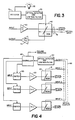
- FIG. 3 illustrates a system design for a fault indication of a single FOL.
- This system comprises a decision means 70, a receiving means 30, which may advantageously include an optical detector and low pass filter as described hereinabove with reference to Figure 2, a WDM 40, a transmitter 50, a fiber 72, and a second means for receiving an optical signal 74.
- the system of Figure 3 operates similarly to the system shown in Figure 2, however, the controller is replaced by a decision circuit 70 which measures the optical power output of the transmitter as detected and converted into electrical energy by the first receiving means 30 and provides an indication 22 if optical transmission falls below a predetermined power level.
- the second receiving means 74 receives a second optical input of energy concentrated at wavelength ⁇ 2 a from an optical source not shown.
- a second receiving means would be advantageously employed in a full duplex FOL.
- FIG 4 illustrates schematically a system designed for fault isolation of a plurality of transmitters.
- the reflected transmitter output R of multiple WDMs 40 (numbered WDM 1 to WDM N) are coupled together optically and routed to an optical detector 30.
- the detector interfaces to the controller 80.
- the controller 80 tests each transmitter individually by switching each switch 90 "on” individually using well known switching logic and measuring the optical output power.
- the fault indication signal flags link failures and identifies the faulty individual transmitter.
- Optional driver control lines may also be included to provide power control of the transmitters from the controller as shown by Line 54 in Figure 2.
- any number of transmitters can be tested and controlled by a controller adapted to route inputs through switches to individual transmitters so as to allow the inputs to pass through the switches when the switches are closed and to block the inputs for any switches which are open.
Landscapes
- Physics & Mathematics (AREA)
- Electromagnetism (AREA)
- Engineering & Computer Science (AREA)
- Computer Networks & Wireless Communication (AREA)
- Signal Processing (AREA)
- Optical Communication System (AREA)
- Arrangements For Transmission Of Measured Signals (AREA)
- Investigating Or Analysing Materials By Optical Means (AREA)
Applications Claiming Priority (2)
| Application Number | Priority Date | Filing Date | Title |
|---|---|---|---|
| US331866 | 1981-12-17 | ||
| US07/331,866 US4991229A (en) | 1989-04-03 | 1989-04-03 | Optical transmitter power measurement and control |
Publications (1)
| Publication Number | Publication Date |
|---|---|
| EP0391285A1 true EP0391285A1 (fr) | 1990-10-10 |
Family
ID=23295720
Family Applications (1)
| Application Number | Title | Priority Date | Filing Date |
|---|---|---|---|
| EP90106219A Withdrawn EP0391285A1 (fr) | 1989-04-03 | 1990-03-31 | Appareil de mesure et de contrôle de la puissance optique d'un émetteur |
Country Status (4)
| Country | Link |
|---|---|
| US (1) | US4991229A (fr) |
| EP (1) | EP0391285A1 (fr) |
| JP (1) | JP2913004B2 (fr) |
| CA (1) | CA2012116C (fr) |
Families Citing this family (12)
| Publication number | Priority date | Publication date | Assignee | Title |
|---|---|---|---|---|
| US5396357A (en) * | 1994-01-25 | 1995-03-07 | Honeywell Inc. | Fault tolerant optical cross-channel data link |
| SE506403C2 (sv) | 1996-09-13 | 1997-12-15 | Ericsson Telefon Ab L M | Transmissionssystem med återkopplad optisk förstärkare |
| SE514609C2 (sv) | 1996-09-13 | 2001-03-19 | Ericsson Telefon Ab L M | System och förfarande för reglering av uteffekten hos en optisk förstärkare |
| JPH10164018A (ja) * | 1996-11-26 | 1998-06-19 | Fujitsu Ltd | 光送信機並びに該光送信機を有する端局装置及び光通信システム |
| SE9703000D0 (sv) | 1997-10-21 | 1997-08-20 | Ericsson Telefon Ab L M | Optical amplifier control |
| US6542287B1 (en) * | 2000-12-12 | 2003-04-01 | Onetta, Inc. | Optical amplifier systems with transient control |
| US6904784B2 (en) * | 2001-02-27 | 2005-06-14 | Teledyne Isco, Inc. | Liquid chromatographic method and system |
| US8750702B1 (en) * | 2002-06-21 | 2014-06-10 | Rockstar Consortium Us Lp | Passive optical loopback |
| JP2004245550A (ja) | 2003-02-17 | 2004-09-02 | Fujikura Ltd | 還流特性に優れたヒートパイプ |
| CN109379131B (zh) * | 2018-12-04 | 2022-06-17 | 中国航空工业集团公司西安航空计算技术研究所 | 高可靠光纤通信系统光链路在线监测装置和故障检测方法 |
| US11569913B2 (en) * | 2020-06-19 | 2023-01-31 | Huawei Technologies Co., Ltd. | Optical modulator control system for interconnect transceivers |
| CN114696903B (zh) * | 2020-12-31 | 2023-10-13 | 华为技术有限公司 | 一种光模块、处理装置、插接装置、系统以及方法 |
Citations (4)
| Publication number | Priority date | Publication date | Assignee | Title |
|---|---|---|---|---|
| DE2838299B2 (de) * | 1977-09-05 | 1980-09-11 | Cselt-Centro Studi E Laboratori Telecomunicazioni S.P.A., Turin (Italien) | Verfahren und Vorrichtung zur sendeseitigen Aufbereitung eines elektrischen Digitalsignals für die optische Faserleitungsübertragung |
| US4307469A (en) * | 1980-04-18 | 1981-12-22 | Harris Corporation | Injection laser diode digital transmitter having signal quality monitoring arrangement |
| US4709416A (en) * | 1986-02-24 | 1987-11-24 | Rca Corporation | Laser bias current stabilization for burst mode fiber optic communication system |
| US4817098A (en) * | 1985-05-17 | 1989-03-28 | Fuji Photo Film Co., Ltd. | Semiconductor laser driver system |
Family Cites Families (4)
| Publication number | Priority date | Publication date | Assignee | Title |
|---|---|---|---|---|
| US4215323A (en) * | 1978-01-13 | 1980-07-29 | Bell Telephone Laboratories, Incorporated | Instability and regenerative pulsation in optical cavities |
| JPS5555591A (en) * | 1978-10-19 | 1980-04-23 | Kokusai Denshin Denwa Co Ltd <Kdd> | Semiconductor light amplifier |
| US4485475A (en) * | 1983-05-27 | 1984-11-27 | The Mitre Corporation | Optical source peak wavelength control using a wavelength feedback network |
| US4805235A (en) * | 1986-02-17 | 1989-02-14 | Nec Corporation | Optical transmitter comprising an optical frequency discriminator |
-
1989
- 1989-04-03 US US07/331,866 patent/US4991229A/en not_active Expired - Fee Related
-
1990
- 1990-03-14 CA CA002012116A patent/CA2012116C/fr not_active Expired - Fee Related
- 1990-03-31 EP EP90106219A patent/EP0391285A1/fr not_active Withdrawn
- 1990-04-03 JP JP2087644A patent/JP2913004B2/ja not_active Expired - Lifetime
Patent Citations (4)
| Publication number | Priority date | Publication date | Assignee | Title |
|---|---|---|---|---|
| DE2838299B2 (de) * | 1977-09-05 | 1980-09-11 | Cselt-Centro Studi E Laboratori Telecomunicazioni S.P.A., Turin (Italien) | Verfahren und Vorrichtung zur sendeseitigen Aufbereitung eines elektrischen Digitalsignals für die optische Faserleitungsübertragung |
| US4307469A (en) * | 1980-04-18 | 1981-12-22 | Harris Corporation | Injection laser diode digital transmitter having signal quality monitoring arrangement |
| US4817098A (en) * | 1985-05-17 | 1989-03-28 | Fuji Photo Film Co., Ltd. | Semiconductor laser driver system |
| US4709416A (en) * | 1986-02-24 | 1987-11-24 | Rca Corporation | Laser bias current stabilization for burst mode fiber optic communication system |
Also Published As
| Publication number | Publication date |
|---|---|
| US4991229A (en) | 1991-02-05 |
| JPH0367399A (ja) | 1991-03-22 |
| JP2913004B2 (ja) | 1999-06-28 |
| CA2012116C (fr) | 2000-05-30 |
| CA2012116A1 (fr) | 1990-10-03 |
Similar Documents
| Publication | Publication Date | Title |
|---|---|---|
| US5093568A (en) | Monitoring system for fiber optic cables utilizing an OTDR for detection of signal loss and automatic location of faults in the cable | |
| US5179420A (en) | Optical time domain reflectometer using a tunable optical source | |
| EP2274595B1 (fr) | Réflectomètre temporel optique | |
| US4991229A (en) | Optical transmitter power measurement and control | |
| US4341438A (en) | Light source arrangement in an optical communication system | |
| US4749247A (en) | Self-monitoring fiber optic link | |
| US5051578A (en) | Self calibrating fiber optic sensor system with optimized throughput | |
| KR0123893B1 (ko) | 광전송로의 고장위치를 판별하는 방법 및 이 방법에 사용하는 광필터형 판별기 | |
| US7596315B2 (en) | Wavelength division multiplexing optical transmission system and transmission wavelength control method therefor | |
| WO1985002476A3 (fr) | Systeme a fibres optiques avec capacite de test automatique | |
| EP3985376B1 (fr) | Système d'inspection de trajet de transmission optique, et dispositif d'inspection de trajet de transmission optique | |
| US4942294A (en) | Fiber optic sensing apparatus for multiplexing a plurality of optical signals of different wavelengths over a single fiber optic cable | |
| EP0462580A1 (fr) | Gyromètre à fibre optique avec autodiagnostic | |
| US6574017B1 (en) | Wavelength division multiplex transmitter | |
| US7720384B2 (en) | Wavelength division multiplexing apparatus | |
| EP1126264B1 (fr) | Reflectometre optique a domaine temporel | |
| EP0949776A2 (fr) | Emetteur optique, émetteur optique à plusieurs longueurs d'onde et méthode de transmission optique | |
| EP0879401B1 (fr) | Dispositifs de compensation et de controle d'etat pour des capteurs a fibres optiques a modulation d'intensite | |
| EP0657719B1 (fr) | Système de capteur optique multiple | |
| US5191208A (en) | Fiber optic sensor system with a redundancy means and optimized throughout | |
| US5923797A (en) | Frequency-controlled optical switch | |
| JP3064913B2 (ja) | 光伝送路障害点検出装置 | |
| EP1322006A1 (fr) | Dispositif de détection de décalage de longueur d'onde et méthode | |
| JPH0120578B2 (fr) | ||
| KR20010035997A (ko) | 파장 분할 다중화 시스템에서의 다채널 광신호 감시 장치 |
Legal Events
| Date | Code | Title | Description |
|---|---|---|---|
| PUAI | Public reference made under article 153(3) epc to a published international application that has entered the european phase |
Free format text: ORIGINAL CODE: 0009012 |
|
| AK | Designated contracting states |
Kind code of ref document: A1 Designated state(s): DE FR GB IT |
|
| 17P | Request for examination filed |
Effective date: 19910328 |
|
| 17Q | First examination report despatched |
Effective date: 19930219 |
|
| STAA | Information on the status of an ep patent application or granted ep patent |
Free format text: STATUS: THE APPLICATION HAS BEEN WITHDRAWN |
|
| 18W | Application withdrawn |
Withdrawal date: 19930830 |