EP0391418B2 - Diamant für Abrichtungsvorrichtung - Google Patents
Diamant für Abrichtungsvorrichtung Download PDFInfo
- Publication number
- EP0391418B2 EP0391418B2 EP90106545A EP90106545A EP0391418B2 EP 0391418 B2 EP0391418 B2 EP 0391418B2 EP 90106545 A EP90106545 A EP 90106545A EP 90106545 A EP90106545 A EP 90106545A EP 0391418 B2 EP0391418 B2 EP 0391418B2
- Authority
- EP
- European Patent Office
- Prior art keywords
- diamond
- wire drawing
- single crystal
- faces
- diamonds
- Prior art date
- Legal status (The legal status is an assumption and is not a legal conclusion. Google has not performed a legal analysis and makes no representation as to the accuracy of the status listed.)
- Expired - Lifetime
Links
Images

Classifications
-
- B—PERFORMING OPERATIONS; TRANSPORTING
- B21—MECHANICAL METAL-WORKING WITHOUT ESSENTIALLY REMOVING MATERIAL; PUNCHING METAL
- B21C—MANUFACTURE OF METAL SHEETS, WIRE, RODS, TUBES, PROFILES OR LIKE SEMI-MANUFACTURED PRODUCTS OTHERWISE THAN BY ROLLING; AUXILIARY OPERATIONS USED IN CONNECTION WITH METAL-WORKING WITHOUT ESSENTIALLY REMOVING MATERIAL
- B21C3/00—Profiling tools for metal drawing; Combinations of dies and mandrels for metal drawing
- B21C3/02—Dies; Selection of material therefor; Cleaning thereof
- B21C3/025—Dies; Selection of material therefor; Cleaning thereof comprising diamond parts
-
- B—PERFORMING OPERATIONS; TRANSPORTING
- B28—WORKING CEMENT, CLAY, OR STONE
- B28D—WORKING STONE OR STONE-LIKE MATERIALS
- B28D5/00—Fine working of gems, jewels, crystals, e.g. of semiconductor material; apparatus or devices therefor
- B28D5/0005—Fine working of gems, jewels, crystals, e.g. of semiconductor material; apparatus or devices therefor by breaking, e.g. dicing
- B28D5/0011—Fine working of gems, jewels, crystals, e.g. of semiconductor material; apparatus or devices therefor by breaking, e.g. dicing with preliminary treatment, e.g. weakening by scoring
-
- C—CHEMISTRY; METALLURGY
- C30—CRYSTAL GROWTH
- C30B—SINGLE-CRYSTAL GROWTH; UNIDIRECTIONAL SOLIDIFICATION OF EUTECTIC MATERIAL OR UNIDIRECTIONAL DEMIXING OF EUTECTOID MATERIAL; REFINING BY ZONE-MELTING OF MATERIAL; PRODUCTION OF A HOMOGENEOUS POLYCRYSTALLINE MATERIAL WITH DEFINED STRUCTURE; SINGLE CRYSTALS OR HOMOGENEOUS POLYCRYSTALLINE MATERIAL WITH DEFINED STRUCTURE; AFTER-TREATMENT OF SINGLE CRYSTALS OR A HOMOGENEOUS POLYCRYSTALLINE MATERIAL WITH DEFINED STRUCTURE; APPARATUS THEREFOR
- C30B29/00—Single crystals or homogeneous polycrystalline material with defined structure characterised by the material or by their shape
- C30B29/02—Elements
- C30B29/04—Diamond
-
- C—CHEMISTRY; METALLURGY
- C30—CRYSTAL GROWTH
- C30B—SINGLE-CRYSTAL GROWTH; UNIDIRECTIONAL SOLIDIFICATION OF EUTECTIC MATERIAL OR UNIDIRECTIONAL DEMIXING OF EUTECTOID MATERIAL; REFINING BY ZONE-MELTING OF MATERIAL; PRODUCTION OF A HOMOGENEOUS POLYCRYSTALLINE MATERIAL WITH DEFINED STRUCTURE; SINGLE CRYSTALS OR HOMOGENEOUS POLYCRYSTALLINE MATERIAL WITH DEFINED STRUCTURE; AFTER-TREATMENT OF SINGLE CRYSTALS OR A HOMOGENEOUS POLYCRYSTALLINE MATERIAL WITH DEFINED STRUCTURE; APPARATUS THEREFOR
- C30B33/00—After-treatment of single crystals or homogeneous polycrystalline material with defined structure
-
- H—ELECTRICITY
- H10—SEMICONDUCTOR DEVICES; ELECTRIC SOLID-STATE DEVICES NOT OTHERWISE PROVIDED FOR
- H10W—GENERIC PACKAGES, INTERCONNECTIONS, CONNECTORS OR OTHER CONSTRUCTIONAL DETAILS OF DEVICES COVERED BY CLASS H10
- H10W40/00—Arrangements for thermal protection or thermal control
- H10W40/20—Arrangements for cooling
- H10W40/25—Arrangements for cooling characterised by their materials
- H10W40/254—Diamond
Definitions
- the present invention relates to a synthetic single crystal diamond for a dresser.
- EP-A-0136408 a publication of the present applicant, discloses the use of type lb diamond containing from to 5 to 100 ppm nitrogen as a wire drawing die.
- Diamond has the highest hardness and modulus of elasticity of any existing material. Furthermore, extremely pure diamond also has the highest thermal conductivity and highest transmittance of infrared light. Thus, diamond is one of the precious resources that cannot be replaced by other materials.
- the present invention is applicable to diamond synthesized by the temperature gradient method.
- diamond crystal dies are made of natural diamond, whose (110) or (111) faces are polished and then at least one vertical face to said faces is also polished for devisvation of the formation of a hole in the diamond. After the preparations, a wire drawing hole which is vertical to (110) or (111) faces is formed by a laser beam, electric discharge or ultrasonic grinding, while observing through the polished face. Synthetic diamond crystals are put on the market and various efforts to apply them for wire drawing are carried out.
- the faults of a natural diamond crystal wire drawing die include the following. It is said that a die having a wire drawing hole vertical to the (110) face has generally the highest wear resistance and the longest life. See Junkatsu (Lubrication), vol 112, No. 11, 1967. However, the tool life of such dies is variable, for the following reasons.
- synthesized or slightly polished idiomorphic diamond is generally used for wire drawing dies.
- a hexahedron diamond is suitable. This is mainly covered with (100) faces, and the wire drawing holes are thus vertical to the (100) faces.
- a drawing hole of such direction has inferior wear resistance and a short tool life.
- some synthetic diamonds lack uniform concentration of nitrogen. This can cause uneven wear of the drawing hole.
- a cutting blade in which diamond particles are embedded rotates at high speed, presses forward on the diamond and performs the cutting.
- the other is thermal cutting, for example, using a laser beam. See, for example, US-A-4401876 for a proposal to form a groove in a gemstone diamond, using a laser.
- a diamond is grooved by the other diamond or a cutting blade and then a knife-shaped wedge is struck into the groove thereby to cleave the diamond, as shown on pages 411-412 of Kesshokogaku Handbook.
- the latter is thought to be the best method to divide a diamond economically, taking advantage of diamond's propensity to be easily cleaved parallel to the (111) faces.
- the method does not require a width loss equal to the cutting blade, especially when compared to the former method and also does not require a great deal of time to divide.
- the angle between the groove and the cleavage plane (111) faces must be at most 0.5°.
- using another diamond or a cutting blade it is impossible to groove with such accuracy because a diamond is hard enough to get such an accuracy of 0.5°.
- the linearity of the groove has to be within 0.1 mm, but it is very difficult using the prior art to achieve such accuracy.
- An object of the present invention is to provide a diamond for a dresser made of a synthetic single crystal diamond.
- a diamond as claimed in claim 1 below Disclosed below is process for manufacturing a diamond for wire drawing die which involves a groove on a single crystal diamond, which groove is parallel to the (111) faces and is made by an energy beam selected from an electron beam, an ion beam and laser beam, and then a wedge is struck into the groove to divide the single crystal diamond.
- Fig. 1 is a schematic diagram of the process to make a wire drawing die
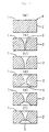
- Fig. 2 is a cross sectional view, showing a wire drawing hole in each step of Fig. 1
- Fig. 3 is a cross sectional view of the cleavage plane
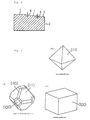
- Fig. 4 shows typical single crystal diamonds
- Fig. 4(a) is an octa-hexahedron
- Fig. 4(b) is an octahedron
- Fig. 4(c) is a hexahedron.
- This invention relates to a synthetic single crystal diamond of an lb type which contains nitrogen between 20 - 400 ppm and synthesized as by the temperature gradient method.
- the nitrogen in the synthetic single crystal diamond of an lb type is isolated and distributed.
- the concentration of the nitrogen exceeds 400 ppm, the wear increases.
- the concentration of the nitrogen is below 20 ppm, the diamond only partially wears.
- the wire drawing hole wears unevenly because of the difference of the concentration of nitrogen. Then the wire drawing hole is transformed to an irregular shape useless for wire drawing. Or the wire drawing hole becomes enlarged rapidly, and a short tool life is the result.
- This specification discloses a wire drawing die whose drawing direction is parallel to the ⁇ 111 ⁇ direction and whoses hole is built precisely vertical to the (111) faces using a cleavage plane (111) as a standard plane to minimize the discrepancy from the ⁇ 111 ⁇ direction.
- the present inventors found that the wear resistance of synthetic single crystal diamond is not so dependent upon the face index as a natural diamond. Concerning the synthetic single crystal diamond, the wear of the ⁇ 100 ⁇ direction is great, but the wear of the ⁇ 111 ⁇ and ⁇ 110 ⁇ directions, was less than the 100 direction and nearly the same as each other. Generally, the wear resistance of natural diamond strongly depends on the direction of the crystal, and the wear of the ⁇ 111 ⁇ direction is less than the ⁇ 110 ⁇ direction.
- the wear resistance of the wire drawing hole depends strongly on the discrepancy of the angle between the center line of the drawing hole and the ⁇ 111 ⁇ direction.
- the cleavage plane of the (111) faces can be used as the standard plane and the wire drawing hole can be made precisely vertical to the cleavage plane.
- a diamond synthesized by the temperature gradient method is mostly idiomorphic. Therefore it is precise and easy to discriminate the plane index, and also it is easy to cleave the (111) faces of the desired size of an idiomorphic single crystal diamond. In addition, it is found that the cleavage plane of the synthetic diamond is smooth and even. In many cases, the cleavage planes of natural diamonds have cleavage bandings, many large steps and spiral steps. Furthermore, other (111) faces appear, having different directions.
- the surface roughness of the standard cleavage plane (111) is at most 100 ⁇ m.
- the surface roughness is equal to the height of a step 6 between two cleavage plane 1.
- a plane 2, cut by a laser beam, is shown.
- the height and the number of steps are important factors, and the preferable embodiment is a 30 - 100 ⁇ m height and also at most 3 steps of 1 mm lengths.
- At least one side is roughened by cutting thermally, for example, using a laser beam, to increase the friction coefficient.
- the surface of a grown synthetic diamond is smoother than the surface of natural diamond, and much stress is indispensable to hold the wire drawing die to the tool holder using the rough surfaces. When holding on a polished surface, a large stress is also necessary. Such large stress causes cracking of the die during drawing.
- the preferable surface roughness is between 5 to 100 ⁇ m.
- a large compressive stress to hold the die to the tool holder is unavoidable due to a small friction coefficient.
- the surface roughness is more than 100 ⁇ m, a stress concentration occurs on the uneven surface and this causes the initiation of cracking.
- a (111) plane of synthetic single crystal rough diamond may be used as the standard plane for making the wire drawing hole to lower the angle discrepancy.
- this method is inferior in that the shape of the wire drawing die becomes close to the shape of a single diamond and whose shape is not easily controlled.
- a single diamond having a large (111) plane area must be selected.
- the first is that a surface of a single crystal diamond is grooved parallel to the (111) faces by the use of an ion beam, an electron beam or a laser beam.
- the (111) faces of the single crystal diamond are adjusted parallel to the X or Y axis of the table and also parallel to the energy beam and then the single crystal diamond is easily grooved. This process if preferred as an effective means for the next cleavage process, in order to cleave reliably and precisely without the considerable skill required in the prior art techniques.
- a sharp plate such as a wedge or a knife made of metal or ceramics is set into the groove and the sharp plate is forced into the groove parallel to the (111) faces and then the single crystal diamond is divided completely. Hammering, pressing, or the stress of thermal expansion can be used as a means to force the sharp plate into the groove.
- the length of the wedge is longer than that of the groove, however, there is no limit to the length of the wedge. Specifically, the length of the knife should be shorter than the groove. Furthermore, a needle is occasionally used as a wedge. This improved process represents an improvement in ease, reliability and precision to divide a diamond, compared to the prior art.
- the method using a laser beam has been said to be the most reliable and precise method to divide a single crystal diamond. Since the groove becomes V shaped, when the energy beam is used, good results are obtained.
- a large and a good quality synthetic single crystal diamond is more preferable than a natural single crystal diamond, because it is reliable, easy and precise to divide a single crystal diamond.
- most natural single crystal diamonds were dissolved in the earth, with surfaces which are curved or uneven, and therefore it is difficult to identify the (111) faces from the external appearance, whose faces are indispensable for cleavage of single crystal diamond.
- the synthetic single crystal diamond is generally polyhedron surrounded by the (111) faces and the (100) faces as shown in Fig.
- a synthetic single crystal diamond which is larger than 1.5 mm in diameter, larger than 1/30 carat size and of high quality, is superior to a synthetic crystal diamond which is generally called an abrasive in the market and smaller than 1 mm in diameter.
- the abrasive is too small to handle and the quality is not sufficient for use as a wire drawing die.
- the cleavage plane (111) can be used as the standard plane to build the wire drawing hole.
- the hole When the wire drawing hole become enlarged from normal wear and erosion, the hole can be reshaped for drawing larger wire.
- FIG. 2 shows the shape of the wire drawing hole corresponding to Fig. 1.
- a diamond for wire drawing die A in Fig. 2 (a) (1 is cleavage plane, 2 is the cut side by laser) had an initial hole 3 made by the laser bean as shown in Fig. 2 (b), and then the surface of the initial hole was polished smooth by ultrasonic machining as shown in Fig. 2 (c).
- A had an initial hole 4 made by the laser beam as shown in Fig. 2 (d), and then the surface of the initial hole was also polished smooth by ultrasonic machining as shown in Fig. 2 (e).
- a wire passed through the wire drawing hole 5 to provide a finish and the wire drawing die was obtained as shown in Fig. 2 (f).
- the diameter of the wire drawing hole was 40 ⁇ m determined by measuring the diameter of the wire.
- Each wire drawing die was settled in a holder and employed for copper drawing.
- Table 1 shows that the wire drawing dies which contain nitrogen between 20 to 400 ppm, have excellent properties .
- the other three diamonds were polished substituted for cleavage into plates of 1.1 mm thickness. Then, the diamonds were worked into the wire drawing die which had 30 ⁇ m diameter wire drawing holes and a size of 1.4 mm x 1.4 mm x 1.1 mm using the same process as Example 1.
- the wire drawing holes were vertical to the surfaces of 1.4 mm x 1.4 mm.
- the concentration of nitrogen in the diamond was between 80 to 100 ppm. This concentration was estimated from the infra-red absorption coefficient at 1130 cm -1 .
- the height of the steps on the cleavage plane was between 50 to 60 ⁇ m.
- the surface roughness of the cut side by laser beam was between 25 to 30 ⁇ m.
- the surface roughness of the polished side was 0.1 ⁇ m.
- Table 2 shows that the wire drawing dies having a cleavage plane as (111) faces is preferable to having a polished plane, and the wire drawing dies having an angle between 87 - 90° were preferred embodiments, and the angle between 89 - 90° were the best embodiments.
- a single crystal diamond of 0.8 carat size was synthesized under a pressure of 5.5 GPa and a temperature of 1350°C, employing the temperature gradient method and Fe-50 Ni as the solvent metal, and then the single crystal diamond was cleaved into two plates each 0.6 mm thick.
- Two wire drawing dies were made from each plate by the same process as example 1 and the sizes were 1 mm x 1 mm x 0.6 mm.
- the diameter of drawing wire was 30 ⁇ m.
- the wire drawing dies which had a step height below 100 ⁇ m had an advantage over the others.
- Table 4 shows that the diamonds whose surface texture was between 5 to 100 ⁇ m, provided better results.
- Seventy natural diamonds which were of a 1.0 - 1.1 carat size of a octahedron like roundness, and did not contain impurities except for trace amounts of nitrogen, were divided into seven sets and each set consisted of 10 natural diamonds.
- Ten synthetic diamonds which were also of a 1.0 - 1.1 carat size in a hexa-octahedron as in Fig. 4 (a) and did not contain impurities except for trace amounts of nitrogen, were prepared. These eighty diamonds were provided for the following cutting tests, and Table 5 shows the results. All the diamonds were cut in two using the four prior art methods and the four methods of our present disclosure. The ratio of those suffering no destruction using cleavage is shown in Table 5.
- a disk of 0.15 mm thickness made of phosphor bronze was inserted in the cutting machine and a kneaded mixture of about 10 ⁇ m diamond powder with machine oil was rubbed on the circumference of the blade.
- the blade was rotated at 8,000 r p.m and then the blade ground the surface of a natural diamond, and the diamond was cut. Marks of the blade were revealed on the cut surface and also the cut surface had a curve of more than 0.1 mm.
- a natural diamond was set on a X-Y table, and then cut by a YAG laser bean of 20 watts, moving the table in a prescribed direction. There were many vertical stripes on the cut side due to the pulse laser. Furthermore the cut side had an inclination of 2 - 6° to the laser beam, and was not parallel to the vertical direction of the table. The inclination around the inlet portion of the laser beam differed from the inclination around the outlet portion, therefore the cut side was curved.
- the natural diamond was set on the X-Y table with the (111) faces parallel to the Y axis: a surface of the natural diamond was grooved by a YAG laser beam of 5 watts and the X-Y table moved toward the Y axis.
- the groove had a 0.08 mm width at the inlet of the laser beam, 0.3 mm depth and has V-shaped.
- a steel wedge having a lead angle of 20° was wedged into the groove by a hammer, and the natural diamond was cleaved.
- the cleavage plane was more flat than the plane obtained by experimetal Nos. 23 and 24.
- the natural diamond was set on an X-Y table in the same way as experimental No. 25 whose table was settled in a vacuum chamber, and then the pressure of the vacuum chamber was lowered to 0.013 Pa (10 -4 torr).
- the natural diamond was cleaved in the same way as No. 25.
- a synthetic diamond of a 1.0 carat size having a hexa-octahedron shape was put in the place of a natural diamond as in experiment No. 25.
- the other processes were the same as for No. 25.
- each set consisted of ten (10) diamonds of 1.0 - 1.1 carat size and the diamonds were divided into 0.5 mm thick plates. The results are shown in Table 6.
- Experiment No. 31 in table 6 shows that the objective of a plate of a 0.5 mm thickness could not be obtained using the process of Experiment No. 23.
- the plates were cut by laser into rectangular shapes. Then the rectangular pieces were holed and polished to be made into wire drawing dies.
- the plates were cut by laser into stick-like shapes. Then several pieces were mounted into steel shanks and finished as dressers.
- the top and bottom faces of the plates were polished and cut by laser into rectangular shapes. Next the surfaces were metalized. Then the heat-sinks were finished.
Landscapes
- Chemical & Material Sciences (AREA)
- Engineering & Computer Science (AREA)
- Crystallography & Structural Chemistry (AREA)
- Materials Engineering (AREA)
- Metallurgy (AREA)
- Organic Chemistry (AREA)
- Mechanical Engineering (AREA)
- Metal Extraction Processes (AREA)
- Crystals, And After-Treatments Of Crystals (AREA)
Claims (1)
- Diamant für eine Abrichtungsvorrichtung, der einen Diamant mit einem Stickstoffgehalt von 20 bis 400 ppm umfaßt, wobei der genannte Diamant ein synthetischer Einkristalldiamant vom Typ Ib ist; und zumindest eine von zwei Flächen des genannten Diamanten durch Spaltung parallel zu einer (111)-Ebene ausgebildet und dann durch einen Laser in eine stabartige Form geschnitten wird.
Applications Claiming Priority (4)
| Application Number | Priority Date | Filing Date | Title |
|---|---|---|---|
| JP88517/89 | 1989-04-06 | ||
| JP1088517A JPH0712485B2 (ja) | 1989-04-06 | 1989-04-06 | 線引きダイス用素材および該素材を用いた線引きダイス |
| JP1277393A JPH085055B2 (ja) | 1989-10-25 | 1989-10-25 | ダイヤモンドの加工方法 |
| JP277393/89 | 1989-10-25 |
Publications (3)
| Publication Number | Publication Date |
|---|---|
| EP0391418A1 EP0391418A1 (de) | 1990-10-10 |
| EP0391418B1 EP0391418B1 (de) | 1995-01-25 |
| EP0391418B2 true EP0391418B2 (de) | 1998-09-09 |
Family
ID=26429880
Family Applications (1)
| Application Number | Title | Priority Date | Filing Date |
|---|---|---|---|
| EP90106545A Expired - Lifetime EP0391418B2 (de) | 1989-04-06 | 1990-04-05 | Diamant für Abrichtungsvorrichtung |
Country Status (3)
| Country | Link |
|---|---|
| US (1) | US5560241A (de) |
| EP (1) | EP0391418B2 (de) |
| DE (1) | DE69016240T3 (de) |
Families Citing this family (13)
| Publication number | Priority date | Publication date | Assignee | Title |
|---|---|---|---|---|
| JP2725660B2 (ja) * | 1995-11-29 | 1998-03-11 | 住友電気工業株式会社 | ドレッサー用単結晶ダイヤモンドチップおよびダイヤモンドドレッサー |
| IL124592A (en) | 1997-05-23 | 2002-07-25 | Gersan Ets | Method of marking a gemstone or diamond |
| US6616725B2 (en) | 2001-08-21 | 2003-09-09 | Hyun Sam Cho | Self-grown monopoly compact grit |
| US6736223B2 (en) | 2001-12-05 | 2004-05-18 | Halliburton Energy Services, Inc. | Thrust control apparatus |
| WO2005029511A1 (ja) * | 2003-09-17 | 2005-03-31 | Sumitomo Electric Industries, Ltd. | 超電導機器および超電導ケーブル |
| US7791188B2 (en) | 2007-06-18 | 2010-09-07 | Chien-Min Sung | Heat spreader having single layer of diamond particles and associated methods |
| TWI394928B (zh) * | 2009-12-18 | 2013-05-01 | Ritedia Corp | A hot plate with single layer diamond particles and its related methods |
| US9006086B2 (en) | 2010-09-21 | 2015-04-14 | Chien-Min Sung | Stress regulated semiconductor devices and associated methods |
| WO2012040373A2 (en) | 2010-09-21 | 2012-03-29 | Ritedia Corporation | Diamond particle mololayer heat spreaders and associated methods |
| US8778784B2 (en) | 2010-09-21 | 2014-07-15 | Ritedia Corporation | Stress regulated semiconductor devices and associated methods |
| MX2018000741A (es) * | 2015-07-22 | 2018-05-15 | Almt Corp | Dado de diamante. |
| KR102626684B1 (ko) * | 2015-07-22 | 2024-01-17 | 스미토모덴키고교가부시키가이샤 | 단결정 다이아몬드재, 단결정 다이아몬드칩 및 천공 공구 |
| CN114653937B (zh) * | 2020-12-22 | 2024-09-10 | Tdk株式会社 | 热加工磁铁用的挤压模具及使用其的热加工磁铁的制造方法 |
Family Cites Families (10)
| Publication number | Priority date | Publication date | Assignee | Title |
|---|---|---|---|---|
| US4122636A (en) * | 1973-09-14 | 1978-10-31 | Roy Alexander R | Synthetic RD diamond particles |
| US4181505A (en) * | 1974-05-30 | 1980-01-01 | General Electric Company | Method for the work-hardening of diamonds and product thereof |
| US4333986A (en) * | 1979-06-11 | 1982-06-08 | Sumitomo Electric Industries, Ltd. | Diamond sintered compact wherein crystal particles are uniformly orientated in a particular direction and a method for producing the same |
| US4401876A (en) * | 1980-05-20 | 1983-08-30 | Martin Cooper | Working gemstones |
| SE457537B (sv) * | 1981-09-04 | 1989-01-09 | Sumitomo Electric Industries | Diamantpresskropp foer ett verktyg samt saett att framstaella densamma |
| US4617181A (en) * | 1983-07-01 | 1986-10-14 | Sumitomo Electric Industries, Ltd. | Synthetic diamond heat sink |
| US4935303A (en) * | 1987-10-15 | 1990-06-19 | Canon Kabushiki Kaisha | Novel diamond-like carbon film and process for the production thereof |
| JPH0288498A (ja) * | 1988-06-13 | 1990-03-28 | Sumitomo Electric Ind Ltd | ダイヤモンドレーザ結晶およびその作製方法 |
| JPH0620464B2 (ja) * | 1989-04-03 | 1994-03-23 | 信越化学工業株式会社 | 医療用切開、圧入器具およびその製造方法 |
| US5127983A (en) * | 1989-05-22 | 1992-07-07 | Sumitomo Electric Industries, Ltd. | Method of producing single crystal of high-pressure phase material |
-
1990
- 1990-04-05 EP EP90106545A patent/EP0391418B2/de not_active Expired - Lifetime
- 1990-04-05 DE DE69016240T patent/DE69016240T3/de not_active Expired - Lifetime
-
1995
- 1995-06-07 US US08/484,258 patent/US5560241A/en not_active Expired - Lifetime
Also Published As
| Publication number | Publication date |
|---|---|
| DE69016240T3 (de) | 1999-03-11 |
| DE69016240T2 (de) | 1995-06-29 |
| EP0391418B1 (de) | 1995-01-25 |
| DE69016240D1 (de) | 1995-03-09 |
| EP0391418A1 (de) | 1990-10-10 |
| US5560241A (en) | 1996-10-01 |
Similar Documents
| Publication | Publication Date | Title |
|---|---|---|
| EP0391418B1 (de) | Diamant für Ziehstein, Wärmesenke oder Abrichtungsvorrichtung, Verfahren zur Herstellung der Diamant und Ziehstein damit hergestellt | |
| EP0099486B1 (de) | Diamant-Einkristalle, Verfahren zu deren Herstellung und Werkzeuge zum Gebrauch derselben | |
| US5601477A (en) | Polycrystalline abrasive compact with honed edge | |
| US4481016A (en) | Method of making tool inserts and drill bits | |
| EP1606077B1 (de) | Präzisionsmittel zum schärfen und erzeugen von mikroklingen entlang von schneidkanten | |
| EP0920363B1 (de) | Verfahren zur herstellung eines schneideinsatzes für schneidwerkzeug | |
| US6007916A (en) | Synthetic single crystal diamond for wiring drawing dies and process for producing the same | |
| US4802895A (en) | Composite diamond abrasive compact | |
| JPH0623157A (ja) | ナイフ刀身 | |
| US3596649A (en) | Abrasive tool and process of manufacture | |
| EP4253345A2 (de) | Gesinterte plättchenförmige zufällig geformte schleifpartikel und verfahren zur herstellung davon | |
| JPH08206989A (ja) | カッタ及びカッタの製造方法 | |
| US20050103534A1 (en) | Cutting tip for diamond tool and diamond tool | |
| DE69606688T2 (de) | Einsatz aus Diamant-Monokristall für Abrichtwerkzeug und ihn anwendendes Abrichtwerkzeug | |
| KR940002036B1 (ko) | 와이어드로우잉 다이용 소재 및 와이어드로우잉 다이 | |
| KR940002022B1 (ko) | 다이아몬드의 가공방법 | |
| EP0036754B1 (de) | Abrichten und Formen von Schleifscheiben | |
| US4694710A (en) | Method of making a blank of a drill bit | |
| KR100805442B1 (ko) | 연마 용품 | |
| Zhou et al. | Effects of novel rotary-abrasive finishing pad textures on the controlled 2-body abrasive wear of Type 304 stainless steel | |
| CA1289796C (en) | Steel abrading elements for mass finishing of workpieces and methods of making and using same | |
| US3951012A (en) | Process for making a file and article resulting therefrom | |
| JP2761321B2 (ja) | 砥 粒 | |
| JP2761322B2 (ja) | 砥 粒 | |
| RU2094217C1 (ru) | Способ изготовления ограночного диска |
Legal Events
| Date | Code | Title | Description |
|---|---|---|---|
| PUAI | Public reference made under article 153(3) epc to a published international application that has entered the european phase |
Free format text: ORIGINAL CODE: 0009012 |
|
| AK | Designated contracting states |
Kind code of ref document: A1 Designated state(s): DE FR GB NL |
|
| 17P | Request for examination filed |
Effective date: 19900925 |
|
| 17Q | First examination report despatched |
Effective date: 19930705 |
|
| GRAA | (expected) grant |
Free format text: ORIGINAL CODE: 0009210 |
|
| AK | Designated contracting states |
Kind code of ref document: B1 Designated state(s): DE FR GB NL |
|
| REF | Corresponds to: |
Ref document number: 69016240 Country of ref document: DE Date of ref document: 19950309 |
|
| ET | Fr: translation filed | ||
| PLBI | Opposition filed |
Free format text: ORIGINAL CODE: 0009260 |
|
| 26 | Opposition filed |
Opponent name: DE BEERS INDUSTRIAL DIAMOND DIVISION (PROPRIETARY) Effective date: 19951025 |
|
| NLR1 | Nl: opposition has been filed with the epo |
Opponent name: DE BEERS INDUSTRIAL DIAMOND DIVISION (PROPRIETARY) |
|
| PLBF | Reply of patent proprietor to notice(s) of opposition |
Free format text: ORIGINAL CODE: EPIDOS OBSO |
|
| PLBF | Reply of patent proprietor to notice(s) of opposition |
Free format text: ORIGINAL CODE: EPIDOS OBSO |
|
| PLAW | Interlocutory decision in opposition |
Free format text: ORIGINAL CODE: EPIDOS IDOP |
|
| APAC | Appeal dossier modified |
Free format text: ORIGINAL CODE: EPIDOS NOAPO |
|
| APAE | Appeal reference modified |
Free format text: ORIGINAL CODE: EPIDOS REFNO |
|
| APAC | Appeal dossier modified |
Free format text: ORIGINAL CODE: EPIDOS NOAPO |
|
| PLAW | Interlocutory decision in opposition |
Free format text: ORIGINAL CODE: EPIDOS IDOP |
|
| PUAH | Patent maintained in amended form |
Free format text: ORIGINAL CODE: 0009272 |
|
| STAA | Information on the status of an ep patent application or granted ep patent |
Free format text: STATUS: PATENT MAINTAINED AS AMENDED |
|
| 27A | Patent maintained in amended form |
Effective date: 19980909 |
|
| AK | Designated contracting states |
Kind code of ref document: B2 Designated state(s): DE FR GB NL |
|
| NLR2 | Nl: decision of opposition | ||
| ET3 | Fr: translation filed ** decision concerning opposition | ||
| NLR3 | Nl: receipt of modified translations in the netherlands language after an opposition procedure | ||
| REG | Reference to a national code |
Ref country code: GB Ref legal event code: IF02 |
|
| APAH | Appeal reference modified |
Free format text: ORIGINAL CODE: EPIDOSCREFNO |
|
| PGFP | Annual fee paid to national office [announced via postgrant information from national office to epo] |
Ref country code: NL Payment date: 20090427 Year of fee payment: 20 Ref country code: FR Payment date: 20090417 Year of fee payment: 20 Ref country code: DE Payment date: 20090402 Year of fee payment: 20 |
|
| PGFP | Annual fee paid to national office [announced via postgrant information from national office to epo] |
Ref country code: GB Payment date: 20090401 Year of fee payment: 20 |
|
| REG | Reference to a national code |
Ref country code: NL Ref legal event code: V4 Effective date: 20100405 |
|
| REG | Reference to a national code |
Ref country code: GB Ref legal event code: PE20 Expiry date: 20100404 |
|
| PG25 | Lapsed in a contracting state [announced via postgrant information from national office to epo] |
Ref country code: NL Free format text: LAPSE BECAUSE OF EXPIRATION OF PROTECTION Effective date: 20100405 |
|
| PG25 | Lapsed in a contracting state [announced via postgrant information from national office to epo] |
Ref country code: GB Free format text: LAPSE BECAUSE OF EXPIRATION OF PROTECTION Effective date: 20100404 |
|
| PG25 | Lapsed in a contracting state [announced via postgrant information from national office to epo] |
Ref country code: DE Free format text: LAPSE BECAUSE OF EXPIRATION OF PROTECTION Effective date: 20100405 |